

Abstract
This paper presents an overview of the design and control of a fully self-contained prosthesis, which is intended to improve the mobility of transfemoral amputees. A finite-state based impedance control approach, previously developed by the authors, is used for the control of the prosthesis during walking and standing. The prosthesis was tested on an unilateral amputee subject for over-ground walking. Prosthesis sensor data (joint angles and torques) acquired during level ground walking experiments at a self-selected cadence demonstrates the ability of the device to provide a functional gait similar to normal gait biomechanics. Battery measurements during level ground walking experiments show that the self-contained device provides over 4,500 strides (9.0 km of walking at a speed of 5.1 km/h) between battery charges.
I. Introduction
There are more than 300,000 transfemoral amputees [1] in the United States (i.e., an incidence of approximately one per thousand people), with 30,000 new transfemoral amputations conducted each year [2]. If similar trends hold across the world population, then one would expect approximately 7 million transfemoral amputees worldwide. One of the most significant limitations of current prosthetic technology is the inability to provide net power at the joints. This loss of net power generation at the lower limb impairs the ability of the prosthesis to restore biomechanically normal locomotive function during many locomotive activities, including level walking, walking up stairs and slopes, running and jumping [3–10]. In the absence of net power generation at the knee and ankle, transfemoral amputees with passive prostheses have been shown to expend up to 60% more metabolic energy [11] and exert three times the affected-side hip power and torque [3] when compared to healthy subjects during level walking. It is the hypothesis of this work that an actively powered knee and ankle prosthesis with the capability of generating human-scale net positive power over a gait cycle will provide improved functional restoration relative to passive prostheses.
Some of the earliest work in powered transfemoral prostheses was conducted during 1970’s and 1980’s and is described in [12–18]. An electro-hydraulically actuated knee joint, which was tethered to a hydraulic power source and utilized off-board electronics and computation, was developed and tested on at least one amputee subject. As described in [16], an “echo control” scheme was developed for gait control. In this control approach, the modified knee trajectory from the sound leg was used as a desired knee joint angle trajectory on the contralateral side. Other prior work reported the development of an active knee joint actuated by DC motors [19] that utilized a finite state knee controller with robust position tracking control for gait control. Ossur, a prosthetics company, has recently introduced the “Power Knee” that uses a control approach, which like echo control, utilizes sensors on the sound leg [20] to prescribe a trajectory for the knee joint of the prosthesis. In [21], the authors discuss a biomimetic prosthesis with an agonist-antagonist knee.
Work in powered transtibial prostheses includes [22], which describes the design of an active ankle joint using McKibben pneumatic actuators. Ossur has also introduced a “powered” ankle prosthesis, called the “Proprio Foot,” which does not contribute net power to gait, but rather quasi-statically adjusts the ankle angle to avoid stumbling and to better accommodate sitting [23]. An active robotic ankle prosthesis with two actuated degrees of freedom is described in [24]. A powered ankle-foot prosthesis that incorporates both parallel and series elasticity to reduce peak motor torque requirements and to increase bandwidth is described in [25].
Unlike any of the aforementioned prior works, this paper describes a transfemoral prosthesis that combines a powered knee and a powered ankle into one device. Note that, as described in [26], the authors have developed previously a pneumatically powered knee and ankle prosthesis prototype, which was designed to leverage recent advances in monopropellant based pneumatic actuation described [27–30]. In order to provide a technology that is more appropriate for near-term use, the authors describe in this paper a powered knee and ankle prosthesis powered by a lithium-polymer battery. Such batteries have an energy density approaching 200 W·h/kg [31], which as described herein, enables the development of a transfemoral prosthesis with a reasonable weight and an acceptable, although limited, range of locomotion. The energy density of such batteries is expected to nearly double in the next decade [31], which will provide a significantly improved range of locomotion. Prior to developing the self-contained, battery-powered powered knee and ankle prosthesis described herein, the authors have previously reported on the development of a tethered, electrically powered knee and ankle prototype, which was used to develop the controllers, validate hardware requirements, and investigate the electrical power requirements of such a device [32]. Based on this preliminary work, the authors have developed an electrically powered self-contained active knee and ankle prosthesis, which is described herein. The self-contained prosthesis generates human-scale power at the joints and incorporates a torque-based control framework for stable and coordinated interaction between the prosthesis and the user. This paper describes the mechanical and electrical design of the prosthesis, provides an overview of the finite-state based impedance control framework for walking and standing, presents experimental results on a single transfemoral amputee subject, and discusses the electrical power requirements in different activity modes.
II. Prosthesis Design
The joint torque specifications required of the knee and ankle joints were based on an 85 kg user for a walking cadence of 80 steps per minute and stair climbing, as derived from body-mass-normalized data [3, 10]. The joint power specifications were based on data from Winter [3], also for an 85 kg user. The structural design requirements were based on a user mass of 115 kg and a minimum factor of safety of two (i.e. the structure was designed to accommodate the loads imposed by a 230 kg user). The design specifications are summarized in Table I. The resulting self-contained powered knee and ankle prosthesis is shown in Fig. 1. A detailed discussion of the mechanical, sensor and embedded system design is given in the following sections.
Table I.
Design specifications
| Specification | Value |
|---|---|
| Knee Range of Motion | 0° to 120° |
| Ankle Range of Motion | −45° to 20° |
| Maximum Knee Torque | 75 Nm |
| Maximum Ankle Torque | 130 Nm |
| Peak Knee Power | 150 W |
| Peak Ankle Power | 250 W |
| Knee Center Height Adjustability | 0.45 m to 0.58 m |
| Maximum Total Weight | 4.5 kg |
| Minimum Factor of Safety | 2 |
Fig. 1.
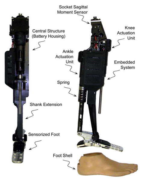
The self-contained powered knee and ankle transfemoral prosthesis, front and side views.
A. Mechanical Design
The design of self-contained prosthesis utilizes same slider-crank mechanisms designed for the pneumatic prosthesis outlined in [26]. In this design, two motor driven motor ball screw assemblies, instead of pneumatic pistons, are utilized in a slider crank configuration to actuate the knee and ankle joints. The prosthesis is capable of 120° of flexion at the knee and 35° of planterflexion and 20° of dorsiflexion at the ankle. Each actuation unit consists of a Maxon EC30 Powermax brushless motor capable of producing 200 W of continuous power connected to a 12 mm diameter ball screw with 2 mm pitch. The ankle actuation unit additionally incorporates a 302 stainless steel spring (51mm free length and 35mm outer diameter), with 3 active coils and a stiffness of 385 N/cm in parallel with the ball screw. The purpose of the spring is to bias the motor’s axial force output toward ankle plantarflexion, and to supplement power output during ankle push off. The compression spring does not engage until approximately five degrees of ankle plantarflexion. Each actuation unit additionally includes a uniaxial load cell (Measurement Specialties ELPF-500L), positioned in series with the unit for closed loop force control of the motor/ballscrew unit. Both the knee and ankle joints incorporate bronze bearings and, for joint angle measurement, integrated precision potentiometers (ALPS RDC503013). A strain based sagittal plane moment sensor is located between the knee joint and the socket connector, which measures the moment between the socket and prosthesis. The ankle joint connects to a custom foot design which incorporates strain gages to measure the ground reaction forces on the ball of the foot and on the heel.
The central hollow structure of the prosthesis houses and protects a lithium-polymer battery in addition to providing an attachment point for the embedded system hardware. To better fit within an anthropomorphic envelope, the ankle joint is placed slightly anterior to the centerline of the central structure. The length of the shank segment is varied by changing the length of three components; the lower shank extension, the spring pull-down, and the coupler between the ball nut and ankle. Additional adjustability is provided by the pyramid connector that is integrated into the sagittal moment load cell for coupling the prosthesis to the socket (as is standard in commercial transfemoral prostheses). The self-contained transfemoral prosthesis was fabricated from 7075 aluminum and has a total mass of 4.2 kg. A weight breakdown of the device is presented in Table II.
Table II.
Mass of Self-Contained Powered Prosthesis
| Component | Weight (kg) |
|---|---|
| Battery | 0.62 |
| Electronics | 0.36 |
| Knee Motor Assembly | 0.72 |
| Ankle Motor Assembly | 0.89 |
| Custom Foot (with embedded sensing) | 0.35 |
| Foot Shell | 0.24 |
| Sagittal Moment Sensor | 0.12 |
| Remaining Structure | 0.90 |
| Total Weight | 4.20 |
B. Embedded System
The powered prosthesis contains an embedded microcontroller that allows for either tethered or untethered operation. The embedded system consists of signal processing, power supply, power electronics, communications and computation modules, Fig 2. The system is powered by a lithium polymer battery with 29.6 V nominal rating and 4000 mA·h capacity. The signal electronics require ± 12 V and +3.3 V, which are provided via linear regulators to maintain low noise levels. For efficiency, the battery voltage is reduced by PWM switching amplifiers to ± 15 V and +5 V prior to using the linear regulators. The power can be disconnected via a microcontroller that controls a solid state relay. The power status is indicated by LED status indicators controlled also by the microcontroller.
Fig. 2.
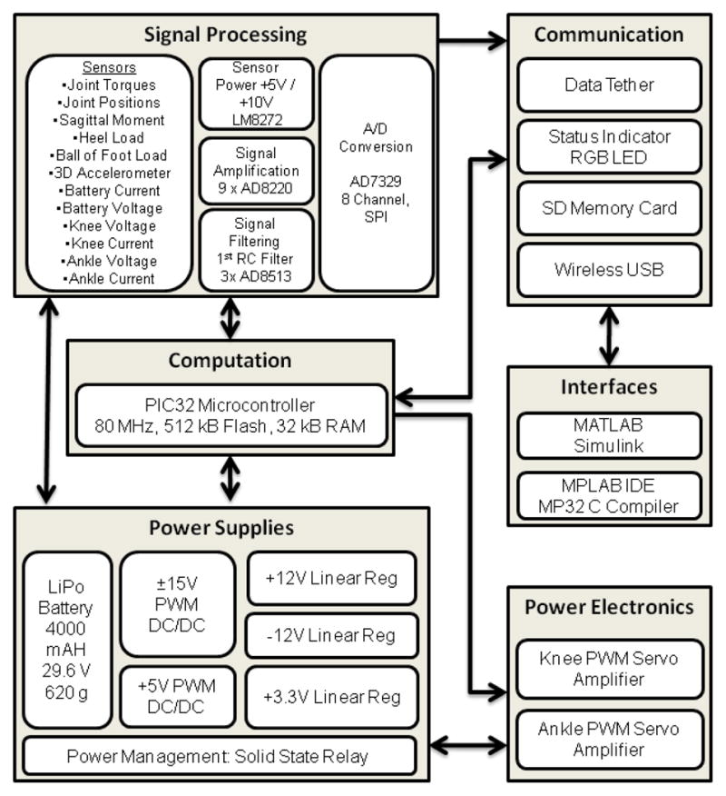
Embedded system framework.
The analog sensor signals acquired by the embedded system include the prosthesis sensors signals (five strain gage signals and two potentiometer signals), analog reference signals from the laptop computer used for tethered operation, and signals measured on the board including battery current and voltage, knee and ankle servo amplifier currents and a three axis accelerometer. The prosthesis sensor signals are conditioned using input instrumentation amplifiers (AD8220) over a range of ±10 V. The battery, knee motor and ankle motor currents are measured by current sensing across 0.02 Ohm resistors and via current sensing amplifiers (LT1787HV). The signals are filtered with a first-order RC filter with 1.6 kHz cut off frequency for the commercial load cells and joint angles and 160 Hz cutoff frequency for the sagittal moment, heel and ball of foot custom load cells and buffered with high slew rate amplifiers before the analog to digital conversion stage. Analog to digital conversion is accomplished by two 8-channel analog to digital convertors (AD7329). The analog to digital conversion data is transferred to the microcontroller via serial peripheral interface (SPI) bus.
The main computational element of the embedded system is an 80 MHz PIC32 microcontroller with 512 kB flash memory and 32 kB RAM, which consumes approximately 0.4 W of power. The microcontroller is programmed in C using MPLAB IDE and MP32 C Compiler. The prosthesis controller is implemented at 1000 Hz sampling frequency on the microcontroller. The prosthesis can be controlled via a tether by a laptop computer running MATLAB Simulink RealTime Workshop, also operating at 1000 Hz. In the untethered operation state, the microcontroller performs the servo and activity controllers of the prosthesis and also logs the sensor data at every 5 ms. In the tethered operation state, the microcontroller drives the servo amplifiers based on analog reference signals from the laptop computer. A 1.0 GB SD memory card is used for logging time-stamped data acquired from the sensors and recording internal controller information at every 5 ms. The SD memory card is interfaced to the computer via wireless USB protocol. The microcontroller sends PWM reference signals to two four quadrant brushless DC motor drivers (Advanced Motion Control AZBDC20A8) rated at 12A continuous and 20A peak current output with regenerative capabilities in the second and forth quadrants of the velocity/torque curve. The embedded system printed circuit board is a 130 mm × 90 mm 4-layer board designed for surface mount technology (SMT) components. The weight of the embedded system is 0.36 kg, consisting of the board and components (0.10 kg), servo amplifiers (0.19 kg), and protective cover (0.07 kg).
C. Control
The general control architecture of the prosthesis consists of three levels, as diagrammed in Fig. 3. The high level supervisory controller, which is the intent recognizer, infers the user’s intent based on the interaction between the user and the prosthesis, and switches the middle level controllers appropriately. Intent recognition is achieved by first generating a database containing sensor data from different activity modes, then training a pattern recognizer that switches between activity modes in real time, as described in [32]. A middle level controller is developed for each activity mode, such as walking, standing, sitting, and stair ascent/descent. The middle level controllers generate torque references for the joints using a finite state machine that modulates the impedance of the joints depending on the phase of the gait. The low-level controllers are the closed-loop joint torque controllers, which compensate for the transmission dynamics of the ball screw (i.e., primarily friction and inertia), and thus enable tracking of the knee and ankle joint torque references (commanded by the middle level controllers) with a higher bandwidth and accuracy than is afforded with an open-loop torque control approach.
Fig. 3.
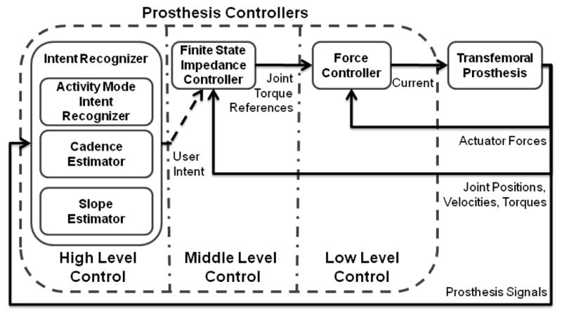
Complete control architecture showing high, middle and low levels.
The finite state impedance control developed by the authors utilizes an impedance-based approach to generate joint torques [26]. The joint torques for each activity mode, such as walking, standing, sitting, stair ascent/descent, are governed by separate finite state machines, which modulate the joint impedance according to the phase of gait. The finite state machines for walking and standing are diagrammed in Figs. 4 and 5, respectively. The state model for walking is described by five phases, three of which are stance phases (early stance, middle stance, and late stance) and two of which are swing phases (swing knee flexion and swing knee extension). The standing state model is described by two phases, which are a weight bearing phase and a non-weight bearing phase. Note that the distinction between torque commands and position commands is largely one of output impedance. That is, accurate tracking of position trajectories requires a high joint output impedance, which is not characteristic of human gait. By generating torque trajectories rather than position trajectories, the output impedance of each joint can be more closely matched to the native limb, thus enabling the user to interact with the prosthesis by leveraging its dynamics in a manner similar to normal gait. In other words, the resulting motion of each prosthesis joint is due to the combination of the user input and the prosthesis input, rather than resulting from the prosthesis input alone (as would be the case with a position-based controller). In each phase, the knee and ankle torques, τi, are each described by a passive spring and damper with a fixed equilibrium point, given by:
| (1) |
where ki, bi, and θki denote the linear stiffness, damping coefficient, and equilibrium point, respectively, for the ith state. Energy is delivered to the user by switching between appropriate equilibrium points (of the virtual springs) during transitions between phases. In this manner, the prosthesis is guaranteed to be passive within each phase, and thus generates power simply by switching between phases. Since the user initiates phase switching, the result is a predictable controller that, barring phase switching input from the user, will always default to passive behavior.
Fig. 4.
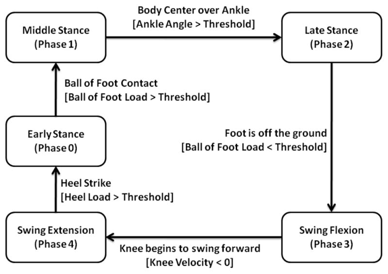
The finite state machine for level walking. Blocks represent states and arrows represent the corresponding transitions.
Fig. 5.
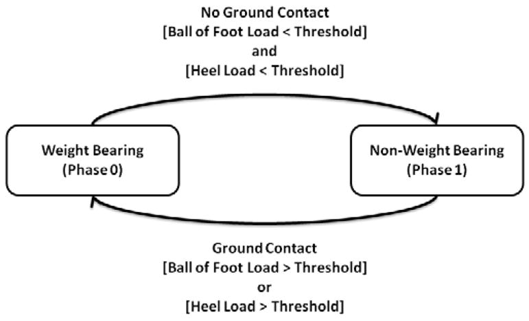
The finite state machine for level standing. Blocks represent states and arrows represent the corresponding transitions.
III. Experiments
The powered prosthesis was tested on a 20-year-old male (1.93 m, 70 kg) unilateral amputee three years post amputation. A photograph of the transfemoral amputee wearing the prosthesis is shown in Fig. 6. The length of the test subject’s residual limb measured from the greater trochanter to the amputated site was 55% of the length of the non-impaired side measured from the greater trochanter to the lateral epicondyle. Thus, the length of the subject’s residual limb is short relative to most transfemoral amputees. The subject uses an Ottobock C-leg with a Freedom Renegade prosthetic foot for daily use. For testing of the powered prosthesis prototype, the subject’s daily-use socket was used, with the height and varus-valgus alignment of the prosthesis adjusted for the initial trial by a licensed prosthetist.
Fig. 6.
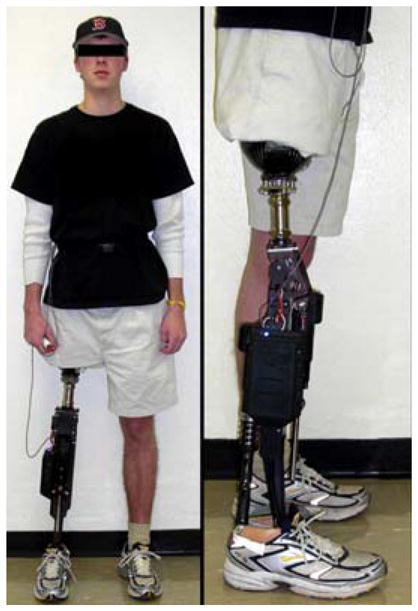
Unilaterial transfemoral amputee test subject used for the powered prosthesis evaluation.
A. Parameter Tuning
Middle level controller parameters (i.e., Eq. (1) for each of the five states) were initially tuned on a treadmill. The nominal cadence used for parameter tuning was the subject’s self-selected cadence while wearing his daily-use prosthesis. This was found by covering the speed indicator on the treadmill and adjusting the treadmill speed until the subject felt comfortable. The self-selected cadence of the subject with the daily-use prosthesis was determined to be 75 steps per minute at 2.8 km/h. Fast and slow cadences were set at ±15 percent of the normal treadmill cadence resulting in treadmill speeds of 2.2 and 3.4 km/h, respectively. For each cadence, the middle level control parameters of the powered prosthesis were tuned (with the prosthesis controlled in the tethered state). Middle level controller parameters were also tuned for standing. During the standing mode, the subject alternately shifted his weight between limbs, turned in place, and stood still. Note that for both walking and standing, the parameters were tuned using a combination of feedback from the user, and from visual inspection of the joint angle, torque, and power data. Note also that the tethered operating mode was utilized during treadmill parameter tuning because it enabled quick and easy parameter variation and data visualization, and thus greatly expedited the iterative parameter tuning process. The resulting middle level controller parameters of the tuned impedance functions for standing and walking at the differing speeds are listed in Tables III and IV.
Table III.
Impedance parameters for treadmill walking from experimental tuning
| Knee Impedance | Ankle Impedance | ||||||
|---|---|---|---|---|---|---|---|
| Phase | Speed km |
k Nm |
b N·s |
θk deg |
k Nm |
b N·s |
θk deg |
| h | deg | m | deg | m | |||
| 0 | 2.2 | 1.5 | 0 | 10 | 3.5 | 0 | −4.4 |
| 2.8 | 1.5 | 0 | 10 | 3.5 | 0 | −4.4 | |
| 3.4 | 1.5 | 0 | 10 | 3.5 | 0 | −4.4 | |
| 1 | 2.2 | 1.5 | 0 | 10 | 3.5 | 0 | −4.4 |
| 2.8 | 1.5 | 0 | 13 | 3.5 | 0 | −4.4 | |
| 3.4 | 2.0 | 0 | 13 | 4.0 | 0 | −4.4 | |
| 2 | 2.2 | 1.5 | 0.05 | 16 | 3.5 | 0 | − 18 |
| 2.8 | 1.5 | 0.05 | 16 | 4.0 | 0 | − 19 | |
| 3.4 | 2.0 | 0.05 | 16 | 4.5 | 0 | − 20 | |
| 3 | 2.2 | 0 | 0.01 | 50 | 0.3 | 0.02 | 0 |
| 2.8 | 0 | 0.01 | 50 | 0.3 | 0.02 | 0 | |
| 3.4 | 0 | 0.01 | 50 | 0.3 | 0.02 | 0 | |
| 4 | 2.2 | 0 | 0.045 | 45 | 0.3 | 0 | 0 |
| 2.8 | 0 | 0.035 | 45 | 0.3 | 0 | 0 | |
| 3.4 | 0 | 0.04 | 45 | 0.3 | 0 | 0 | |
Highlighted parameters vary with walking speed
Table IV.
Impedance parameters for standing from experimental tuning
| Knee Impedance | Ankle Impedance | |||||
|---|---|---|---|---|---|---|
| Phase |
k Nm |
b N·s |
θk deg |
k Nm |
b N·s |
θk deg |
| deg | m | deg | m | |||
| 0 | 2.5 | 0.02 | 0 | 4.0 | 0.05 | −6 |
| 1 | 0 | 0.02 | 0 | 2.0 | 0.05 | −6 |
B. Over-ground Walking
Once the middle level controllers were fully parameterized for standing and walking on the treadmill, the prosthesis was operated untethered, so that the subject could walk over-ground with the fully self-contained prosthesis (i.e., without a tether hindering movement). The subject walked on a straight, 50 m course at a self-selected cadence. As has been documented by others (e.g., see [33]), the mechanics of treadmill walking are not entirely consistent with the dynamics of over-ground walking, and as such the self-selected speeds over-ground are typically significantly faster than self-selected speeds on a treadmill. Consistent with this phenomenon, the subject’s self-selected speed during the over-ground walking tests was 87 steps per minute, which corresponded to a walking speed of 5.1 km/h, both of which were significantly greater than the self-selected treadmill cadence and speed (which were 75 steps minute and 2.8 km/h, respectively). Additionally, the over-ground self-selected speed with the powered prosthesis was 24 percent faster than the self-selected speed with the daily-use (passive) prosthesis (i.e., 5.1 km/h relative to 4.1 km/h), while the respective cadences were quite similar (87 steps/min for the powered, 90 steps/min for the passive). Because the over-ground cadence was essentially the same as the fast treadmill cadence, the fast (3.4 km/h at 86 steps/min) treadmill controller parameters were used for the over-ground trials, but were fine tuned in over-ground walking, as listed in Table V, in order to adjust for the slightly differing mechanics of over-ground gait. Once this fine-tuning procedure was completed, the subject walked on the 50 m course at a self-selected speed for a total of 10 trials while prosthesis data (i.e., servo amplifier currents, battery current and voltage, joint positions, velocities and torques, socket sagittal plane moment, heel and ball of foot loads, three dimensional shank accelerations, and controller state information) were collected at a 200 Hz sampling rate.
Table V.
impedance parameter for level ground walking from experimental tuning
| Phase | Knee Impedance | Ankle Impedance | |||||
|---|---|---|---|---|---|---|---|
| Speed km | k Nm | b N·s | θk deg | k Nm | b N·s | θk deg | |
| h | deg | m | deg | m | |||
| 0 | 5.1 | 2.5 | 0 | 8 | 3.0 | 0.04 | −1 |
| 1 | 5.1 | 4.5 | 0.05 | 8 | 4.5 | 0.04 | 0 |
| 2 | 5.1 | 3.0 | 0.05 | 22 | 6.0 | 0.01 | −18 |
| 3 | 5.1 | 0.1 | 0 | 65 | 0.4 | 0.05 | 0 |
| 4 | 5.1 | 0.2 | 0.04 | 40 | 0.7 | 0.03 | 0 |
Highlighted parameters vary from 3.4 km/h treadmill walking.
The measured joint angles, torques and powers from walking on level ground at the self-selected cadence for ten consecutive strides are shown in Fig. 7. In comparing the knee and ankle angles to prototypical data from normal subjects (e.g., [3]), one can observe that the powered prosthesis and controller provide knee and ankle joint angle profiles quite similar to those observed during normal gait. The ability for the device to provide stance flexion presumably provides cushioning at heel strike and reduces the rise of the body’s center of mass to allow for more efficient gait [34]. As indicated by the data, the powered prosthesis provides knee torques over 40 Nm (during stance flexion) and ankle torques over 120 Nm during toe-off. As shown in the power data, the prosthesis is contributing significant positive power (during stance) at both the knee joint (peak powers of 50 W) and ankle joint (peak powers approaching 250 W). For each stride, the prosthesis delivers 13.8 J of net energy on average at the ankle.
Fig. 7.
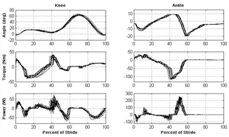
Measured joint angles, torques and powers of the powered prosthesis for ten consecutive gait cycles at self-selected speed (5.1 km/h at 87 steps per minute).
C. Power Consumption and Battery Life
The power source is one of the main challenges in the development of an electrically powered knee and ankle prosthesis. In order to characterize battery requirements, the average electrical power required by the prosthesis (i.e., the embedded system, knee joint motor unit, and ankle joint motor unit) during standing and walking over level ground (at the self-selected speed of 5.1 km/h) is shown in Fig. 8. The total average power consumption for level ground walking and standing is 66 W and 10 W, respectively. Since the prosthesis incorporates a (rechargeable) 118 W·h lithium polymer battery, such electrical power requirements suggest a battery life between charges of approximately 1.8 hours of walking or 12 hours of standing. With these figures, the prosthesis is capable of over 4500 strides (9,000 steps by the user) with the prosthesis at the self-selected cadence. Given the walking speed of 5.1 km/h, the measured power requirements indicate a walking distance (for the amputee subject) of 9.0 km. Note that if the energy density of battery technology doubles over the next five years (as is projected [31]), the walking range between battery charges would approach 20 km.
Fig. 8.
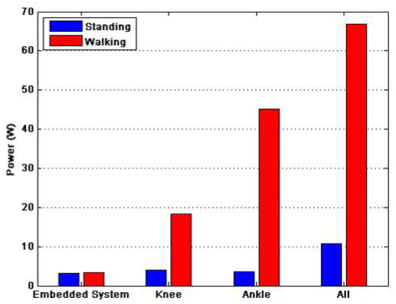
Average electrical power consumption of the powered prosthesis for standing and walking at self-selected speed (5.1 km/h at 87 steps per minute) on normal ground.
IV. Conclusion
The paper describes the design and control of a fully self-contained electrically powered knee and ankle prosthesis capable of producing human-scale power. Experimental results with a unilateral transfemoral amputee indicate that the device can provide biomechanics similar to those typically observed during normal walking. Power consumption measurements on level ground indicate that device consumes 66 W at a walking speed of 5.1 km/h on a 70 kg subject. As such, given the capacity of the on-board battery pack, the prosthesis can provide 9.0 km of level, over-ground walking between recharges. Future works include addressing the audible noise of the device and a comprehensive biomechanical evaluation of the powered prosthesis on multiple amputee subjects.
Supplementary Material
Acknowledgments
This work was supported by the National Institutes of Health grant no. R01EB005684-01. The authors also gratefully acknowledge the support of Otto Bock Healthcare Products for donation of prosthetic components and Mr. Aaron Fitzsimmons, CP, OTR/L for his assistance in prosthetic fitting and gait evaluation.
Contributor Information
Frank Sup, Email: frank.sup@vanderbilt.edu.
Huseyin Atakan Varol, Email: atakan.varol@vanderbilt.edu.
Jason Mitchell, Email: jason.mitchell@vanderbilt.edu.
Thomas J. Withrow, Email: t.withrow@vanderbilt.edu.
References
- 1.Adams PF, Hendershot GE, Marano MA. Current estimates from the National Health Interview Survey, 1996. National Center for Health Statistics Vital Health Stat. 1999;10(200) [PubMed] [Google Scholar]
- 2.Feinglass J, Brown JL, LaSasso A, Sohn MW, Manheim LM, Shah SJ, Pearce WH. Rates of lower-extremity amputation and arterial reconstruction in the United States, 1979 to 1996. American J of Public Health. 1999 Aug;89(8):1222–1227. doi: 10.2105/ajph.89.8.1222. [DOI] [PMC free article] [PubMed] [Google Scholar]
- 3.Winter D. The Biomechanics and Motor Control of Human Gait: Normal, Elderly and Pathological. 2. University of Waterloo Press; 1991. [Google Scholar]
- 4.Winter DA, Sienko SE. Biomechanics of below-knee amputee gait. J of Biomechanics. 1988;21(5):361–367. doi: 10.1016/0021-9290(88)90142-x. [DOI] [PubMed] [Google Scholar]
- 5.DeVita P, Torry M, Glover KL, Speroni DL. A functional knee brace alters joint torque and power patterns during walking and running. J of Biomechanics. 1996 May;29(5):583–588. doi: 10.1016/0021-9290(95)00115-8. [DOI] [PubMed] [Google Scholar]
- 6.Jacobs R, Bobbert MF, van Ingen Schenau GJ. Mechanical output from individual muscles during explosive leg extensions: The role of biarticular muscles. J of Biomechanics. 1996 Apr;29(4):513–523. doi: 10.1016/0021-9290(95)00067-4. [DOI] [PubMed] [Google Scholar]
- 7.Nadeau S, McFadyen BJ, Malouin F. Frontal and sagittal plane analyses of the stair climbing task in healthy adults aged over 40 years: what are the challenges compared to level walking? Clinical Biomechanics. 2003 Dec;18(10):950–959. doi: 10.1016/s0268-0033(03)00179-7. [DOI] [PubMed] [Google Scholar]
- 8.Nagano A, Ishige Y, Fukashiro S. Comparison of new approaches to estimate mechanical output of individual joints in vertical jumps. J of Biomechanics. 1998 Oct;31(10):951–955. doi: 10.1016/s0021-9290(98)00094-3. [DOI] [PubMed] [Google Scholar]
- 9.Prilutsky BI, Petrova LN, Raitsin LM. Comparison of mechanical energy expenditure of joint moments and muscle forces during human locomotion. J of Biomechanics. 1996 Apr;29(4):405–415. doi: 10.1016/0021-9290(95)00083-6. [DOI] [PubMed] [Google Scholar]
- 10.Riener R, Rabuffetti M, Frigo C. Joint powers in stair climbing at different slopes. Proc of the First Joint BMES/EMBS Conf. 1999;1:530. [Google Scholar]
- 11.Waters RL, Perry J, Antonelli D, Hislop H. Energy cost of walking of amputees - Influence of level of amputation. J of Bone and Joint Surgery-American Vol. 1976;58(1):42–46. [PubMed] [Google Scholar]
- 12.Donath M. Massachusetts Institute of Tech. Dept. of Mechanical Eng. Thesis. M.S. 1974. Proportional EMG control for above knee prostheses. [Google Scholar]
- 13.Flowers WC. Massachusetts Institute of Tech. Dept. of Mechanical Eng. Thesis. Ph.D. 1973. A man-interactive simulator system for above-knee prosthetics studies. [Google Scholar]
- 14.Flowers WC, Mann RW. Electrohydraulic knee-torque controller for a prosthesis simulator. ASME J of Biomechanical Engineering. 1977;99(4):3–8. doi: 10.1115/1.3426266. [DOI] [PubMed] [Google Scholar]
- 15.Grimes DL. Massachusetts Institute of Tech. Dept. of Mechanical Eng. Thesis Ph.D. 1979. An active multi-mode above knee prosthesis controller. [Google Scholar]
- 16.Grimes DL, Flowers WC, Donath M. Feasibility of an active control scheme for above knee prostheses. ASME J of Biomechanical Engineering. 1977;99(4):215–221. [Google Scholar]
- 17.Stein JL, Flowers WC. Stance phase-control of above-knee prostheses - Knee control versus SACH foot design. J of Biomechanics. 1987;20(1):19–28. doi: 10.1016/0021-9290(87)90263-6. [DOI] [PubMed] [Google Scholar]
- 18.Stein JL Massachusetts Institute of Technology. Dept. of Mechanical Engineering. Massachusetts Institute of Tech. Dept. of Mechanical Eng. Thesis Ph.D. 1983. Design issues in the stance phase control of above-knee prostheses. [Google Scholar]
- 19.Popovic D, Schwirtlich L. Belgrade active A/K prosthesis. In: de Vries J, editor. Electrophysiological Kinesiology, Intern Congress Ser No 804, Excerpta Medica. Amsterdam, The Netherlands: 1988. pp. 337–343. [Google Scholar]
- 20.Bedard S, Roy P. Actuated leg prosthesis for above-knee amputees. 7,314,490. U S Patent. 2003 June 17;
- 21.Martinez-Villalpando E, Weber J, Elliott G, Herr H. Design of an agonist-antagonist active knee prosthesis. Proc. IEEE/RAS-EMBS Int. Conf. on Biomedical Robotics and Biomechatronics; 2008. pp. 529–534. [Google Scholar]
- 22.Klute GK, Czerniecki J, Hannaford B. Muscle-like pneumatic actuators for below-knee prostheses. Proc. 7th Int. Conf. on New Actuators; 2000. pp. 289–292. [Google Scholar]
- 23.Koniuk W. Self-adusting prosthetic ankle apparatus. 6,443,993. U S Patent. 2001 March 23;
- 24.Bellman R, Holgate A, Sugar T. SPARKy 3: Design of an active robotic ankle prosthesis with two actuated degrees of freedom using regenerative kinetics. Proc. IEEE/RAS-EMBS Int. Conf. on Biomedical Robotics and Biomechatronics; 2008. pp. 511–516. [Google Scholar]
- 25.Au S, Herr H. Powered ankle-foot prosthesis. IEEE Robotics & Automation Magazine. 2008;15:52–59. doi: 10.1109/mra.2019.2955740. [DOI] [PMC free article] [PubMed] [Google Scholar]
- 26.Sup F, Bohara A, Goldfarb M. Design and control of a powered transfemoral prosthesis. Int J of Robotics Research. 2008 Feb;27(2):263–273. doi: 10.1177/0278364907084588. [DOI] [PMC free article] [PubMed] [Google Scholar]
- 27.Fite KB, Goldfarb M. Design and energetic characterization of a proportional-injector monopropellant-powered actuator. IEEE/ASME Trans on Mechatronics. 2006 Apr;11(2):196–204. [Google Scholar]
- 28.Fite KB, Mitchell JE, Barth EJ, Goldfarb M. A unified force controller for a proportional-injector direct-injection monopropellant-powered actuator. J of Dynamic Systems Measurement and Control Trans of ASME. 2006 Mar;128(1):159–164. [Google Scholar]
- 29.Goldfarb M, Barth EJ, Gogola MA, Wehrmeyer JA. Design and energetic characterization of a liquid-propellant-powered actuator for self-powered robots. IEEE/ASME Trans on Mechatronics. 2003;8(2):254–262. [Google Scholar]
- 30.Shields BL, Fite KB, Goldfarb M. Design, control, and energetic characterization of a solenoid-injected monopropellant-powered actuator. IEEE/ASME Trans on Mechatronics. 2006 Aug;11(4):477–487. [Google Scholar]
- 31.In search of the perfect battery. Economist. 2008;3868570:22–24. [Google Scholar]
- 32.Varol HA, Sup F, Goldfarb M. Real-time gait mode intent recognition of a powered knee and ankle prosthesis for standing and walking. Proc. IEEE/RAS-EMBS Int. Conf. on Biomedical Robotics and Biomechatronics; 2008. pp. 66–72. [DOI] [PMC free article] [PubMed] [Google Scholar]
- 33.Traballesi M, Porcacchia P, Averna T, Brunelli S. Energy cost of walking measurements in subjects with lower limb amputations: A comparison study between floor and treadmill test. Gait & Posture. 2008 Jan;27(1):70–75. doi: 10.1016/j.gaitpost.2007.01.006. [DOI] [PubMed] [Google Scholar]
- 34.Blumentritt S, Scherer H, Wellershaus U, Michael J. Design principles, biomechanical data and clinical experience with a polycentric knee offering controlled stance phase knee flexion: A preliminary report. J of Prosthetics and Orthotics. 1997;9(1):18–24. [Google Scholar]
Associated Data
This section collects any data citations, data availability statements, or supplementary materials included in this article.