

Abstract
A core phthalocyanine platform allows engineering the solubility properties the band gap; shifting the maximum absorption toward the red. A simple method to increase the efficiency of heterojunction solar cells uses a self-organized blend of the phthalocyanine chromophores fabricated by solution processing.
Low-cost photovoltaic (PV) devices may derive performance benefits from the light-absorbing properties of phthalocyanine organic dyes because of their high extinction coefficients, stability, and energy band gaps well-matched to the incident solar spectrum.1-4 Despite these desirable attributes, use of phthalocyanines in low-cost solar cells is complicated by their poor solubility in organic solvents (necessitating vacuum deposition processing)2,5,6 and narrow absorption bandwidths at red (Q-band) and ultraviolet (B-band) wavelengths.7 Bulk heterojunction (BHJ) solar cells with dyes such as phthalocyanine5,7,8 and polymer blends have been reported.9,10 There are a several solar cell designs that contain phthalocyanines, especially the zinc and copper complexes, and those that also contain various C60 derivatives wherein the layers are vapor-deposited in specified layers.11-13 Other soluble dye systems have been incorporated into layered devices, or into BHJ solar cells. 4,14-16
We demonstrate a new blend-type parallel tandem solar cell device architecture with several innovative features. (1) Click-type alkyation chemistry on a single commercially available phthalocyanine platform allows design of a series of robust, chemically compatible dyes with tunable optical band gaps and energy levels. (2) The family of soluble phthalocyanine dyes permits solution-based processing of molecular BHJ solar cells. (3) In these devices, the semiconductor active layer is composed of a blend of three phthalocyanine derivatives having different optical band gaps in order to capture a larger fraction of the solar spectrum. (4) Most significantly, a suitable energy level alignment among blended dyes creates a parallel tandem connection that increases the current output of solar cells since all individual dyes contribute to the carrier generation. Furthermore, this scheme is generally applicable to other soluble organic seminconductor blends with proper internal energy alignment.
The ca. 70 nm thick blended phthalocyanine active layer provides a disordered tandem device architecture wherein light can be absorbed by materials with successively smaller band gaps and photogenerated charges are collected with a common complementary organic semiconductor. This demonstrates that a hierarchical organization of dyes, wherein the lowest band gap (red) dye is at the surface and higher band gap (blue) dyes are layered or assembled on top, is not a priori necessary to assure vectoral charge migration between the electrodes.2,17 A standard, reproducible, solution-processed device architecture is used to illustrate these points.9,11
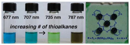
We achieve both improved phthalocyanine solubility and control over the optical properties using high yield substitution of peripheral fluoro groups on hexadecafluorophthalocyanato zinc (ZnPcF16) by thio-alkanes (CH3(CH2)11SH) (Scheme 1).18,19 Because the frontier molecular orbitals (HOMO and LUMO) are primarily delocalized on the ring periphery, substitution of electron withdrawing groups with electron-donating groups affects the orbital energy levels.5,7 The HOMO is destabilized more than the LUMO, resulting in decreased optical band gaps with corresponding maximum absorption wavelengths shifted toward longer wavelengths in the near infrared (Figure 1). Since this effect is additive, one can engineer the light absorption maximum of the dye by balancing the number of electron donating to withdrawing substituents (by varying the reaction conditions: temperature, mole ratio, and base catalyst; see Supporting Information). The products are mixtures of isomers and small amounts of the compounds with ±1-2 thioalkane, so we refer to these products using the wavelength of the Q-band absorption peak in toluene: Pc707, Pc735, and Pc787 (Figure 1). The Pc with four tert-butyl groups, ZnPctBu4 (Pc677) has similar optical absorption spectra and is used because starting ZnPcF16 has poor solubility. The optical band gaps of the resulting pthalocyanine derivatives (Q-band) decrease nearly linearly from ca. 1.83 eV to 1.58 eV with increasing numbers of thioalkanes at a rate of ∼16 meV/thioalkane (Figure 1b). We determined the LUMO level of each derivative from the first reduction potentials measured by cyclic voltammetry and the HOMO level by subtracting the Q-band optical band gap from the LUMO level (Figure 2a).
Scheme 1.
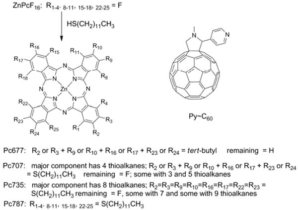
Pc derivatives and the pyridyl∼C60 derivative used. The absorption λmax is used to name each dye system because there are positional isomers on the isoindole. For this nucleophilic substitution reaction the outside, β, positions react first.
Figure 1.
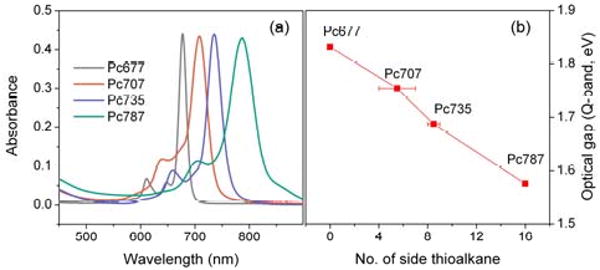
(a) optical absorbance in toluene normalized to the same absorptivity for the lowest energy Q band, (b) Q-band HOMO-LUMO gap energy of the Pcs. (See supporting information.)
Figure 2.
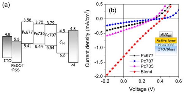
(a) Relative energy levels of the device components. All values are in eV, (b) Current-voltage characteristics of solar cells under 1 Sun AM1.5G condition, inset cell design.
The BHJ solar cells are fabricated with active layer blends of phthalocyanine derivatives with Py∼C60 sandwiched between a poly(3,4-ethylenedioxythiophene): poly(styrenesulfonate) (PEDOT:PSS) on indium tin oxide (ITO) anodes and a C60/Al cathode deposited by thermal evaporation (Figure 2b inset). Note that the C60 evaporated on top of the active layer is part of the electrode design, and serves to make better contacts between the organic and metallic components. In these devices, the phthalocyanine derivatives provide light absorption and hole transport, while the Py∼C60, which can coordinate to the Zn(II) axial positions, facilitates efficient exciton dissociation and electron transport to the electron-collecting contact.20-22 The spin-cast phthalocyanine active layer consists of either an individual derivative or a blend of Pc677, Pc707, and Pc735. Films formed from Pc787 have an inhomogeneous morphology and we were unable to form devices from them. For both individual derivatives and blends of dyes, the optimal device active layer thickness of ca. 70 nm was determined by examining device efficiency versus active layer thickness measured by atomic force microscopy (AFM). The 70 nm thickness represents a balance between maximum incident light absorption and minimal photogenerated carrier recombination. AFM shows that films have a granular topology with no evidence of domains or phase separation (Supporting Information).
The devices were illuminated using a 100 mW/cm2 simulated solar spectrum (1 SUN AM 1.5G), calibrated with a thermopile detector. Devices having a blend of three Pc derivatives show significantly improved performance compared to devices containing only a single dye (Figure 2b). The blend device zero-voltage photocurrent (Jsc) of ca. 1.24 mA/cm2 is more than three times larger than that of the highest single component device (Pc735, Jsc ca. 0.35mA/cm2) and is larger than the combined photocurrent from the three individual dye devices (Figure 2b and Table 1), suggesting that a blended Pc architecture significantly improves the efficiency of photoconversion beyond just the increased light absorption. Tandem organic photovoltaic cells, wherein different thermally evaporated dyes reside in different stacked devices (multijunction cells), can have more than twice the photoconversion efficiency than designs with a single dye.11,23 For the devices reported herein, the best performing found to date have a chromophore ratio Pc677/Pc707/Pc735 of 17/17/66 with a 30% Py∼C60 content (by wt.). Devices having single derivatives in the active layer (Pc677, Pc707, or Pc735) delivered Jsc ca. 0.14-0.35 mA/cm2 (Table 1), similar to recent, previously reported values for this type of cell.17 Additional smaller increases in the open circuit voltage (Voc) of the dye-blend device, combined with the enhanced Jsc improve the overall power conversion efficiency by four-fold from ca. 0.01-0.03% in individual derivatives to 0.12% for the dye-blended device.
Table 1.
Mean PV parameters of devices illuminated with simulated 1 SUN AM1.5G.
| Pc677 | Pc707 | Pc735 | Blend | |
|---|---|---|---|---|
| η (%) | 0.026 | 0.012 | 0.033 | 0.12 |
| JSC (mA/cm2) | 0.26 | 0.14 | 0.35 | 1.24 |
| VOC (V) | 0.351 | 0.375 | 0.305 | 0.408 |
| FF | 0.29 | 0.23 | 0.3 | 0.24 |
The power conversion efficiency (η) of solar cells is expressed as: η = Jsc ·Voc· FF, where Jsc is the short circuit current, Voc is the open circuit voltage, and FF is the fill factor.
The primary performance benefit of the blend device is an increased Jsc due to the three Pc derivative blend components contributing to absorption at different photon energies. Improper relative alignment of energy levels of the Pc derivatives as well as C60 could prevent this device architecture from operating because the individual derivatives may act as carrier recombination centers. An energy diagram constructed from cyclic voltammetry and optical absorption data (Figure 2a) shows possible ‘staircase energy alignments’ for both HOMO and LUMO levels within the blend, suggesting that regardless of their spatial position in the blend layer, generated free holes and electrons always have pathways to the collecting electrodes without recombination in energetically isolated regions. Direct evidence of the contribution of each Pc derivative to free carrier generation is obtained by comparing the blend active layer absorbance to the device input photon to current conversion efficiency (IPCE). The blend film shows a broad absorbance peak between ca. 600-800 nm, resulting from the sum of the optical spectra of the individual Pc derivatives dominated by the Q-bands, and the IPCE response has a nearly identical spectral shape - indicating that each type of derivative contributes to both light absorption and charge generation (Figure 3). Thus, an estimate the device internal quantum efficiency of (2.5/0.1) ca. 25% across all absorbing wavelengths suggests the exciton dissociation and charge collection are equally efficient for all Pc blend components.
Figure 3.
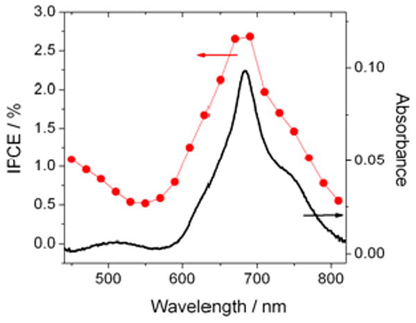
IPCE compared to the absorbance of the blend device.
The best performing Pc blend device built without mixing Py∼C60 in the active layer displayed approximately half of the efficiency, likely due to a less efficient charge separation.24 The Py∼C60 derivative is a good electron acceptor with fast kinetics,25,26 thus Py∼C60 coordination is a key part of the active layer design as also indicated by the poor performance of cells with active layers blended with the underivatized C60. ZnPc generally bind one axial pyridine to form 5-coordinate complexes. In the present case the best devices have about a 2:1 mole ratio of ZnPc dye:Py∼C60 (Figure 4). These observations may indicate charge transfer from a non-coordinated ZnPc to a fullerene on neighboring dye, thereby creating a greater charge separation and contributing to the device performance.27
Figure 4.
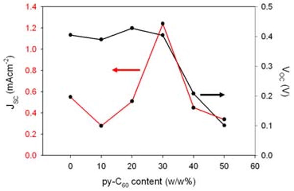
Variation of the Voc and Jsc versus content of Py∼C60 in the blend (a 17:17:66 wt. ratio of Pc677/Pc707/Pc735).
In summary, we demonstrate a new concept of a blended active layer forming a parallel tandem device architecture using bulk heterojunction solar cells made of self-organized blends of Pc derivatives with engineered optical band gaps and energy levels. The copper PcF16 is amenable to same fluorine substitution reactions. Combined with an internal parallel connection, the increased solar spectrum coverage of the blend widens the energy range for converting photons into free carriers, resulting in a ca. four-fold increase in Jsc and PV conversion efficiency over any given Pc component. The suitable alignment of HOMO and LUMO levels among the Pc derivatives and a common complementary fullerene acceptor is key for enabling a parallel charge carrier collection from the device. This new organic PV device scheme is in principle applicable to other blend systems made of high-performance small molecules and conjugated polymers28-30 with proper energy alignment, and may enable higher PV conversion efficiencies thereby facilitating development of practical organic solar cells.
Supplementary Material
Acknowledgments
Supported by: the National Science Foundation (NSF, CHE-0847997 to CMD), the U.S. Department of Energy Divisions of Materials and Chemical Sciences (DE-AC02-98CH10886), and a Goldhaber Distinguished Fellowship to CYN. Hunter College science infrastructure is supported by NSF, National Institutes of Health, including (RCMI, G12-RR-03037), and CUNY. We thank Mr. Matthew Jurow for assistance with some of the control experiments and for duplicating the results described herein.
Footnotes
Supporting Information Available: Pc syntheses, device preparation and characterization. This material is available free of charge via the Internet at http://pubs.acs.org
References
- 1.Leznoff CC, Lever ABP. Phthalocyanines: Properties and Applications. 2-3 Wiley VCH publishers; New York: 1993. [Google Scholar]
- 2.Peumans P, Yakimov A, Forrest SR. J Appl Phys. 2003;93:3693. [Google Scholar]
- 3.Xue J, Rand BP, Uchida S, Forrest SR. Advanced Materials. 2005;17:66. [Google Scholar]
- 4.Perez MD, Borek C, Forrest SR, Thompson ME. J Am Chem Soc. 2009;131:9281. doi: 10.1021/ja9007722. [DOI] [PubMed] [Google Scholar]
- 5.de la Torre G, Claessens CG, Torres T. Chem Commun. 2007:2000. doi: 10.1039/b614234f. [DOI] [PubMed] [Google Scholar]
- 6.Rand BP, Genoe J, Heremans P. Poortmans. J Prog Photovolt: Res Appl. 2007;15:659. [Google Scholar]
- 7.Rio Y, Rodriguez-Morgade MS, Torres T. Org Biomol Chem. 2008;6:1877. doi: 10.1039/b800617b. [DOI] [PubMed] [Google Scholar]
- 8.Honda S, Nogami T, Ohkita H, Benten H, Ito S. Appl Mater Interfaces. 2009;1:804. doi: 10.1021/am800229p. [DOI] [PubMed] [Google Scholar]
- 9.Kim JY, Qin Y, Stevens DM, Ugurlu O, Kalihari V, Hillmyer MA, Frisbie CD. J Phys Chem C. 2009;113:10790. [Google Scholar]
- 10.Rajaram S, Armstrong PB, Kim BJ, Fréchet JMJ. Chem Mater. 2009;21:1775. [Google Scholar]
- 11.Ameri T, Dennler G, Lungenschmied C, Brabec CJ. Energy Environ Sci. 2009;2:347. [Google Scholar]
- 12.Chu WP, Tsai YS, Juang FS, Li TS, Chung CH. PIERS Online. 2007;3:825. [Google Scholar]
- 13.Koeppe R, Sariciftci NS, Troshin PA, Lyubovskaya RN. Appl Phy Lett. 2005;87:244102. [Google Scholar]
- 14.Walker B, Tamayo AB, Dang XD, Zalar P, Jung, Seo H, Garcia A, Tantiwiwat M, Nguyen TQ. Adv Funct Mater. 2009;19:3063. [Google Scholar]
- 15.Hamann TW, Jensen RA, Martinson ABF, Ryswyk HV, Hupp JT. Energy Eviron Sci. 2008;1:66. [Google Scholar]
- 16.Kim JY, Lee K, Coates NE, Moses D, Nguyen TQ, Dante M, Heeger AJ. Science. 2007;317:222. doi: 10.1126/science.1141711. [DOI] [PubMed] [Google Scholar]
- 17.Loi MA, Denk P, Hoppe H, Neugebauer H, Winder C, Meissner D, Brabec C, Sariciftci NS, Gouloumis A, Vázquez P, Torres T. J Mater Chem. 2003;13:700. [Google Scholar]
- 18.Leznoff C, Sosa-Sanchez JL. WO 2005/033110 A1 2005. [Google Scholar]
- 19.Leznoff CC, Sosa-Sanchez JL. Chem Commun. 2004:338. doi: 10.1039/b313253f. [DOI] [PubMed] [Google Scholar]
- 20.Drain CM, Varotto A, Radivojevic I. Chem Rev. 2009;109:1630. doi: 10.1021/cr8002483. [DOI] [PMC free article] [PubMed] [Google Scholar]
- 21.D'Souza F, Ito O. Coord Chem Rev. 2005;249:1410. [Google Scholar]
- 22.Troshin PA, Koeppe R, Peregudov AS, Peregudova SM, Egginger M, Lyubovskaya RN, Sariciftci NS. Chem Mater. 2007;19:5363. [Google Scholar]
- 23.Yakimov A, Forrest SR. Appl Phy Lett. 2002;80:1667. [Google Scholar]
- 24.Brütting W, Bronner M, Götzenbrugger M, Opitz A. Macromol Symp. 2008;268:38. [Google Scholar]
- 25.Illescas BM, Martín N. C R Chimie. 2006;9:1038. [Google Scholar]
- 26.Guldi DM, Prato M. Acc Chem Res. 2000;33:695. doi: 10.1021/ar990144m. [DOI] [PubMed] [Google Scholar]
- 27.Honda S, Nogami T, Ohkita H, Benten H, Ito S. ACS Applied Materials & Interfaces. 2009;1:804. doi: 10.1021/am800229p. [DOI] [PubMed] [Google Scholar]
- 28.Egginger M, Koeppe R, Meghdadi F, Troshin PA, Lyubovskaya RN, Meissner D, Sariciftci NS. Proc of SPIE. 2006;6192:61921Y. [Google Scholar]
- 29.Mak CSK, Leung QY, Chan WK, Djurišišć AB. Nanotechnology. 2008;19:424008. doi: 10.1088/0957-4484/19/42/424008. [DOI] [PubMed] [Google Scholar]
- 30.Martínez-Díaz MV, Díaz DD. J Porphyrins Phthalocyanines. 2009;13:397. [Google Scholar]
Associated Data
This section collects any data citations, data availability statements, or supplementary materials included in this article.