Abstract
In 1991, a novel robot named MIT-MANUS was introduced as a test bed to study the potential of using robots to assist in and quantify the neurorehabilitation of motor function. It introduced a new modality of therapy, offering a highly backdrivable experience with a soft and stable feel for the user. MIT-MANUS proved an excellent fit for shoulder and elbow rehabilitation in stroke patients, showing a reduction of impairment in clinical trials with well over 300 stroke patients. The greatest impairment reduction was observed in the group of muscles exercised. This suggests a need for additional robots to rehabilitate other target areas of the body. Previous work has expanded the planar MIT-MANUS to include an antigravity robot for shoulder and elbow, and a wrist robot. In this paper we present the “missing link”: a hand robot. It consists of a single-degree-of-freedom (DOF) mechanism in a novel statorless configuration, which enables rehabilitation of grasping. The system uses the kinematic configuration of a double crank and slider where the members are linked to stator and rotor; a free base motor, i.e., a motor having two rotors that are free to rotate instead of a fixed stator and a single rotatable rotor (dual-rotor statorless motor). A cylindrical structure, made of six panels and driven by the relative rotation of the rotors, is able to increase its radius linearly, moving or guiding the hand of the patients during grasping. This module completes our development of robots for the upper extremity, yielding for the first time a whole-arm rehabilitation experience. In this paper, we will discuss in detail the design and characterization of the device.
Index Terms: Hand rehabilitation, rehabilitation robotics, rotary to linear, stroke
I. INTRODUCTION
Stroke is the leading cause of permanent impairment and disability [1], and there has been a renewed effort to improve motor recovery after stroke. Although treatment of post stroke recovery in dedicated rehabilitation units positively influences the outcome, no single treatment strategy or protocol has demonstrated superiority. We have been delivering targeted training for the paretic shoulder and elbow with a robotic device, MIT-MANUS, which interactively treats stroke survivors. In randomized controlled trials for persons with both acute and chronic impairments after stroke, over 300 persons treated with the robotic protocol have demonstrated significant reductions in impairment in the exercised limb [2]–[16]. These reductions in motor impairment are in agreement with a prominent theme of current research into recovery, which posits that activity-dependent plasticity underlies neurorecovery.
To increase the effectiveness of robotic therapy we must develop new whole-arm therapy approaches that integrate robotic therapy with clinical practice and enhance the carryover of robot-trained movements during functional tasks. We expect that a treatment protocol, properly targeted to emphasize a sequence and timing of sensory and motor stimuli similar to those naturally occurring in daily life tasks, could facilitate carryover of the observed gains in motor abilities, thereby, conferring greater improvements in functional recovery. A whole-arm therapy approach is a departure from our previous robotic rehabilitation research. Our prior research was based on a “bottom-up” approach, which assumed that improvements in underlying capacities would enhance motor function during activities and tasks. We envision that whole-arm rehabilitation robotics will be guided by a “top-down” rehabilitation approach, in which a person’s identified goals for task performance are used in conjunction with our evaluation data to establish a treatment plan. Robotic technology will not only provide remediation for impairments at the capacity levels (e.g., strength, isolated movement), but will also provide task specific intensive therapy for impaired abilities (e.g., speed or coordination of limb movement) that underlie task performance. One goal of this research is to blend both approaches, and to begin building a scientific basis for the “best” rehabilitation practice. We expect to gain a better understanding of how interventions directed toward one level of performance (i.e., abilities) influence functioning at other levels (e.g., developed capacities, activities, and tasks). We will, thus, extend the focus of robotic therapy from underlying capacities to higher level abilities and skills. To our knowledge, no rehabilitation robotics group can presently pursue this objective because there are no rehabilitation robots that can deliver therapy to the whole-arm, simultaneously manipulating and guiding the shoulder, elbow, wrist, and hand of a stroke patient. We have recently introduced a one-of-a-kind hand robot for the clinic.
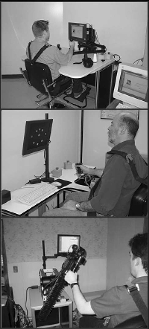
We are now capable of delivering whole-arm robotic therapy for the first time ever. The hand robot complements our previous work for the upper extremity including the ground-breaking planar MIT-Manus for shoulder-and-elbow therapy [18], the antigravity module (spatial training for the shoulder and elbow) [17], and the wrist robot (3 active degrees-of-freedom (DOF): abduction–adduction, flexion–extension, pronation–supination) [19]. Our family of robots (Fig. 1) can be operated as standalone devices or mounted at the tip of another robot of the family. Furthermore, all our robots follow the same design philosophy including backdrivability, which allows us to simulate from “feather-touch” unconstrained movements to hard surfaces. This combination of devices allows us the unique opportunity to test whether the whole-arm functional training is essential or the isolated training of a particular limb segment can achieve similar outcomes.
Fig. 1.
Planar, wrist, and antigravity robots. Top photograph shows the planar shoulder-and-elbow robot (2 active DOFs [18]), middle photograph shows the wrist robot (3 active DOFs [19]), and the bottom photograph shows the antigravity robot (1 active DOF [17]).
II. BACKGROUND
A. State of the Art
Traditional human-assisted therapy has been augmented with several robots designed to administer different modes of therapy to the impaired upper and lower extremity. Few devices were developed to deliver therapy to the hand. Of these few, the one with the largest track record is the Burdea’s pneumatically actuated hand glove, which has a unidirectional mode of actuation (finger extension), and can simulate a virtual object if the subject is able to close the hand [20].
Another hand device is UC Irvine’s HWARD, which allows both flexion and extension. It is a 3-DOF device [21], pneumatically actuated, and backdriveable via three double-acting air cylinders. It produces up to 122.8 N of force (source pressure of 689 kPa). Rotary potentiometers measure the finger, wrist, and thumb joint angles. Pressure sensors are mounted on both sides of each air cylinder, and applied forces are computed from these sensors’ readings. HWARD can assist repetitive grasping and releasing movements, while allowing the subject to feel real objects during therapy.
A third hand device has been developed at the Rehabilitation Institute of Chicago under the auspices of the Sensory Motor Performance Program (SMPP). Their hand manipulator enables controlled rotations of the metacarpophalangeal joints under isokinetic or isometric contraction. It is presently being used to study spasticity [22] and weakness following stroke.
We will conclude this overview mentioning the work being done at the University of Washington. Matsuoka [23] is developing a finger exoskeleton device. It is driven by the users own muscle signals via the use of surface electromyography (EMG) sensors attached to the patient’s arm. Other important contributions [24]–[27] consist in development of exoskeletons for teleoperation and haptic interfaces.
B. Our Contribution to the State of the Art: MIT Hand Robot Alpha-Prototype I
To deliver whole-arm functionally based rehabilitation robotics, we must manipulate a patient’s hand. Our first prototype of the hand robot was completed at MIT in 2001 [30], [31]. Moving the patient’s hand is not a simple task, since the human hand has 15 joints with a total of 22 DOF. Therefore, it was necessary to determine how many DOFs are necessary for a patient to perform the majority of everyday functional tasks.
In the end, several simplifications were made. First and foremost, not all fingers were actuated. The robot actuates the thumb, the index finger, and then, the remainder of the fingers simultaneously in a “mitten” configuration. Secondly, not all finger joints are actuated. It is physically impossible to flex the proximal interphalangeal (PIP) and distal interphalangeal (DIP) joints separately. Therefore, they are actuated together in the robot design, reducing the number of finger DOF to two. Finally, since abduction/adduction is less significant functionally than flexion/extension for most joints, it was eliminated from all joints except the CMC (carpo-metacarpal) of the thumb. These simplifications bring the number of active DOFs to eight.
The number of DOF is only a part of the specification for the joints of the robot. The other part is the range of motion (ROM) of each joint. Although most patients will not be able to accomplish the full ROM of an unimpaired person, it is desirable for the robot to have the ability to reach the full ROM. Table I shows the ROM of each of the robot joints [28]. It is important to note that almost all joints need to be actuated in both directions in order to accomplish full ROM.
TABLE I.
Specified joint ranges of motion
| Finger/Index MCP | 45° Extension | 90° Flexion |
| Finger/Index PIP | 0° Extension | 110° Flexion |
| Thumb CMC | 20° Abduction | 45° Adduction |
| Thumb CMC | 20° Extension | 60° Flexion |
| Thumb MP | 10° Extension | 60° Flexion |
| Thumb IP | 20° Extension | 90° Flexion |
Finally, the robot also needs to provide force to the hand in order to help move the patient’s digits. This force should be sufficient to overcome any tone and spasticity the patient might have, but also must not injure the patient. From a functional point of view, the force provided must allow the patient to complete common tasks such as holding a can or a key. Table II shows the maximum force the robot should provide for each DOF [29]. These force estimates were obtained from a literature review on measured grip forces, as well as by experiments performed in our laboratory.
TABLE II.
Maximum patient force
| Joint | Maximum Force (N) |
|---|---|
| Fingers MCP | 50 |
| Fingers PIP | 25 |
| Index MCP | 30 |
| Index PIP | 15 |
| Thumb CMC | 45 |
| Thumb MP | 30 |
| Thumb IP | 30 |
In addition to these technical specifications, there are also some patient-based requirements that the robot must meet. Most importantly, the robot must be safe. This requirement includes the need for the robot to be backdrivable, as well as the inclusion of software limits in the robot controls. The robot must also be comfortable for the patient, especially since many patients will also be dealing with the discomfort of edema in their hands. Comfort includes being able to fit different-sized patients, and being easy to get on and off. Finally the robot must be compact and aesthetically pleasing in order to not overwhelm patients who have never seen or interacted with a robot before.
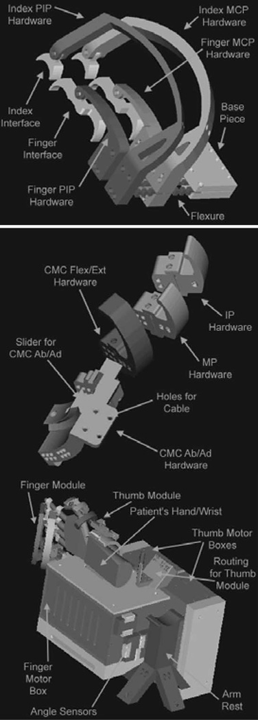
The patient interaction part of the robot can be broken down into the finger module and the thumb module. These modules are designed to be used together but could be separated in later versions of the robot in order to concentrate the therapy. Using both modules allows the patients to practice almost any functional task, including the perceived vital task of finger opposition. Included in the finger module is the hardware for the index finger and the remaining fingers (Fig. 2). The actuated motions are metacarpophalangeal (MCP) flexion/extension and PIP/DIP flexion/extension, giving the module 4 DOF. The index finger hardware must reach over the other fingers, and allow for separate actuation. It is angled back at 45°, since that is the ROM for the index finger MCP if actuated without the other fingers. Flexible pieces are mounted at the end of the cantilevers; these directly interface with the patient. Ergonomic design and foam padding on these pieces increase patient comfort while providing a surface for transmission of force to and from the patient. The thumb module is slightly more complicated. This module also consists of four DOFs: interphalangeal (IP) flexion/extension, MCP flexion/extension, CMC flexion/extension, and CMC abduction/adduction. Flexion/extension of IP, metacarpophalangeal in thumb (MP), and CMC joints is provided by cable-driven flexure joints. However, the CMC abduction and adduction are actuated differently by designing the sliding bearing structure. Initial evaluation of this device revealed that the design must be improved to augment its bandwidth and reduce friction. While this device might eventually lead to a standalone hand robot, the alpha-prototype I was too large and bulky to afford modularity and whole-arm functionally based training.
Fig. 2.
MIT hand robot alpha-prototype I.
Fig. 2 shows the 8-active DOFs design built in 2001 and tested in 2002. It was made by two separate 4 and 4 DOFs modules: the top sketch shows the module with 4-DOFs to manipulate the index finger the middle, ring, and pinkie fingers. The middle sketch shows the 4-DOF module to manipulate the thumb, while the bottom sketch shows the whole device. The device was not fully backdrivable, as significant friction was observed in the cable-drive system and the bandwidth was below 10 Hz [32]; these results led to an unsuitable robotic device for rehabilitation.
III. MIT HAND ROBOT ALPHA-PROTOTYPE II: CONCEPT AND IMPLEMENTATION
Initial tests with our 8-DOF alpha-prototype I demonstrated that the target specifications were not only unrealistic but required a level of complexity, which clinical experience proved to be unwarranted. The perceived “vital” task of finger opposition proved to be far fetched for the typical patient enrolled in robot therapy, who typically had a severe to moderate stroke. For these patients, finger opposition is unrealistic, and we set our goals on training grasp. A revised target specification was adopted in the design of the novel hand module; we relaxed the requirement for finger opposition, limiting it to grasp and release, and promoted modularity to apply the new device to afford whole arm experience. The revised requirements are that it must:
be modular;
be easy to put on and take off (<2 minutes);
be backdrivable;
not cause pain or injury to the patient;
actuate grasp and release function;
have accurate measurement and control of the actuated joint;
include a passive mechanism in order to compensate for hypertonia.
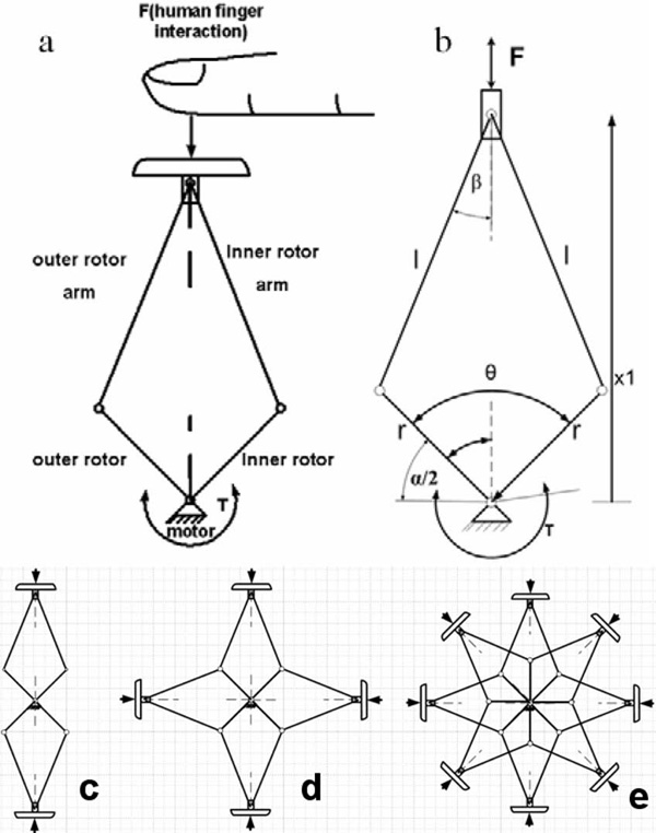
We employed a conventional brushless motor in a novel statorless fashion where the stator of the motor is not connected to a fixed frame but free to rotate: in order to accomplish this requirement the stator and the rotor are both free to rotate with respect to each other, and referred to from now on as inner and outer rotors. Our hand robot is an embodiment of a double crank and slider mechanism (DC&S module) [33] in which the arms are connected to inner and outer rotors and move in opposition. They generate a linear trajectory of a panel, which can be seen as the end-effector interacting with human hand and/or fingers [see Fig. 3(a)].
Fig. 3.
Double crank and slider mechanism. (a) DC&S module interacting with a human finger. (b) Kinematics of the mechanism. (c) Multiple C&S modules with two panels. (d) Multiple C&S modules with four panels. (e) Multiple C&S modules with eight panels.
A brushless rotary electrical actuator is used in order to convert rotational motion into linear motion. The DC&S-module can be stacked in multiples mimicking a cylindrical shape. Fig. 3 shows the kinematic structure with (c) two, (d) four, or (e) eight panels. The mechanism rotates with inner and outer rotors both around a common axis; the rotation is converted to linear motion delivered to the panels by pairs of arms connected to these rotors; the kinematic relation (1) can be deduced by observing Fig. 3(b) as given by
| (1) |
| (2) |
where θ is the angle between the inner and outer rotors and λ is the ratio of r to l, which are the dimension of the mechanism.
The force delivered by the mechanism highly depends on the angle between the inner and outer rotors. The maximum range of motion of the mechanism, before reaching a singularity, is 180° between the stator and the rotor.
The dynamics of the device is similar to that of a crank and slider; the equation of the torque (T) as function of radial force (F) and angle between the outer and inner rotors (θ) can be written as
| (3) |
To avoid the singularity position, the workspace is restricted to a (30°–135°) range of motion via mechanical stops.
A. Mechanical Design
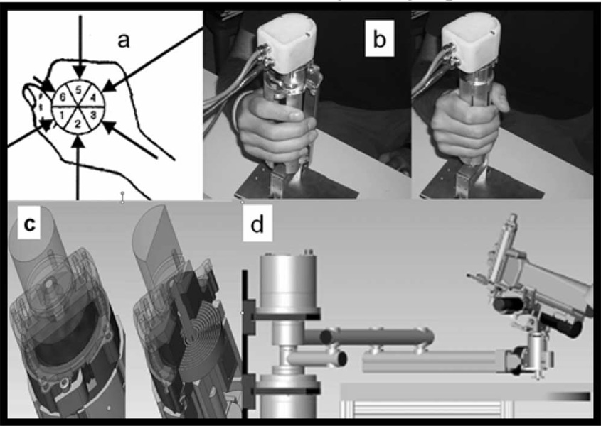
The number of panels was chosen to mimic the shape of the hand [Fig. 4(a)]. Fig. 4(b) shows the hardware with the chosen six-panel configuration. The device is modular, and its external radius dimension is 40 and 77 mm in closed and opened configuration, respectively.
Fig. 4.
(a) Human hand approximated by a six-segment shape. (b) MIT hand module alpha-prototype II (without rubber case). (c) Particular and section of the torsion spring for hypertonicity compensation. (d) 6-DOF workstation for whole arm rehabilitation.
The hand robot is used to simulate grasp and release with its impedance determined by the torque between inner and outer rotors. To compensate for the patient’s hypertonicity, we employed a torsion spring mechanism, which adds a parallel torque to the one delivered by the motor [see Fig. 4(c)]; in this way, a torque offset can be created and the hypertonicity compensated by rotating a ratchet, and consequently charging the torsion spring. Note that we have the rubber casing removed in order to show the structure of the mechanism: the device used for trials with human subjects is equipped with a soft rubber casing to prevent pinching of the fingers; the viscoelastic force introduce by this element has not been considered in this preliminary test of the system; in the future, the implementation of the control will take into account the effect induced by a flexible element such as the rubber case. We are also not showing the Velcro bands, which keep the hand attached to the device during both grasp and release.
IV. EXPERIMENTAL SETUP:SYSTEM CHARACTERIZATION AND PERFORMANCE MEASUREMENT
A. Unconstrained Stability Range
An impedance controller (4) has been implemented with respect to the mutual rotation and velocity of inner and outer rotors where T is the delivered torque k and b is the stiffness and damping, respectively, α is the angular position of the mechanism, and α0 is the reference position
| (4) |
Impedance limits are determined by the value of the gains of the controller for which the system remains stable after an input when it is allowed to evolve in uncoupled configuration.
For patient operation, a critically damped system is desirable; any oscillations would not result in a desirable sensation. To have an idea of the range of acceptable gain values of the controller for which the device remained stable, a simple test was performed. Its goal was to determine the unconstrained stability boundaries. The test consisted of implementing a double FOR loop that varied the proportional and derivative gains of the potential difference (PD) controller. At each iteration, the device was “perturbed” and observed until instability occurred.
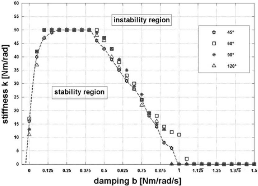
The stability test procedure can be summarized as follows: the system was perturbed by inputting a 5° step into the controller and deemed unstable if the oscillatory behavior did not die out. For a given damping, the stiffness was increased until instability occurred. The ranges of 0–50 Nm/rad and 0–1.5 Nm/rad/s, for the stiffness and damping, were explored, respectively; the outcomes are summarized in Fig. 5.
Fig. 5.
Unconstrained stability map.
The trials were performed for four different rest configurations of the mechanism 45°, 60°, 90°, and 120°, respectively, in order to investigate the effects of configuration dependence on stability. We observed no appreciable dependence on configuration; the dashed curve interpolates the outcomes and traces the bound between the two upper and lower regions where the system is respectively unstable and stable, once the proportional and derivative controller gains are set.
B. Friction Analysis, Maximum Radial Force, and Bandwidth
One of the most important features of interactive robots is backdrivability, i.e., low mechanical impedance seen from the endpoint. Backdrivability depends primarily on the inertia and friction of the system. Using an argument based on human perception, the most restrictive requirements on end point inertia and friction occurs when the robot is in the “passive” configuration (i.e., the robot has no preferred position, and it is not assisting the patient toward an equilibrium point), so that the reference force is the inertial and frictional load felt by the patient at the end point.
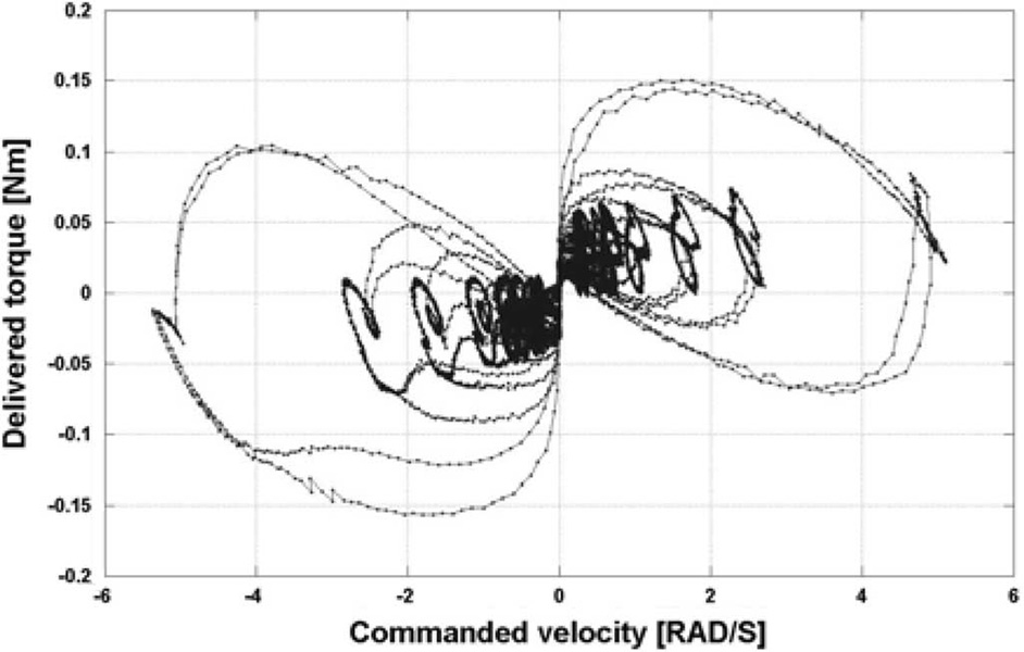
While inertia can be reduced by optimizing the mechanism design, friction cannot be completely avoided, though it is in the best interest of the design to minimize friction. An ad-hoc test was performed to quantify friction forces during motion. In these tests, a constant velocity was input to the motor in order to move it in a range of ±0.5 rad. A plot of the torque delivered by the actuator as a function of speed is shown in Fig. 6.
Fig. 6.
Phase plot of actual torque as function of commanded velocity.
This qualitative analysis of friction showed the system to be characterized primarily by Coulomb rather than viscous friction, but does not provide an accurate evaluation of the friction coefficients.
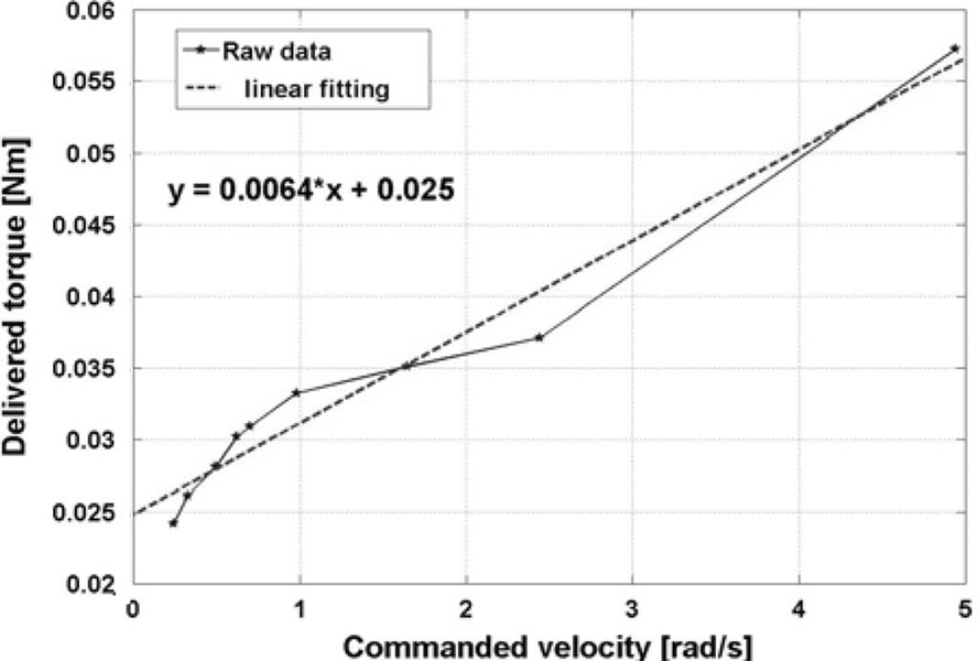
In order to quantify the friction coefficients, we considered ten different values of commanded velocity and their corresponding delivered torques; a linear regression was used to obtain the viscous and Coulomb friction coefficients, where the slope of the line determined the viscous coefficient and the intersection with the torque axis determined the Coulomb friction coefficient (Fig. 7).
Fig. 7.
Linear regression for evaluation of friction coefficients.
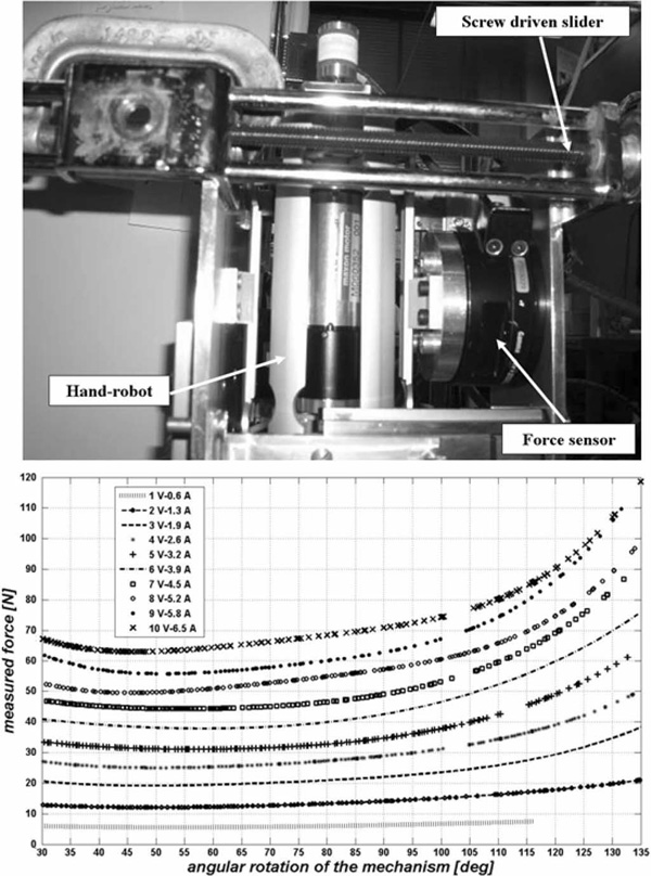
In a different test, we investigated the relation between the actual radial force exerted by the panels as function of the input current to the motor. A custom jig (top panel, Fig. 8) allowed the mechanism to be mounted inside a structure equipped with a force sensor (resolution of 0.0139 N); a manually operated screw driven mechanism moved the force sensor horizontally to map the delivered force at different angular configurations of the device. The bottom panel of Fig. 8 shows the force versus the angular configuration of the device for ten different input current values. The minimum force is delivered when the device is at a 55° angular configuration; the force increases with angle θ, and at 135° the device is able to apply a 120-N maximum force to the external panels before the actuator saturates.
Fig. 8.
Top: customized jig for force measurement in different configurations of the device. Bottom: radial force versus angular configuration at different input currents.
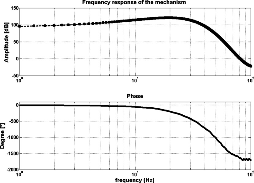
The bandwidth of the system was investigated by a simple sine sweep test; same customized jig from the previous experiment was used to hold the device in a fixed configuration. Sinusoidal current at a known frequency from 1 to 100 Hz was input to the device, and the delivered force was acquired by the force sensor; a Fourier analysis was performed in order to obtain magnitude and phase; as shown in Fig. 9, the response of the system has a cutoff frequency around 20 Hz, making the bandwidth acceptable for rehabilitation purposes.
Fig. 9.
Frequency response of the device.
V. PRELIMINARY HUMAN TRIALS
The device includes sensors for position, velocity, and motor current (used to estimate torque). The external radius of the mechanism during interaction with the patient is given by
| (5) |
where θ is the angle between the inner and outer rotors.
A custom-made current sensor allows us to measure the current in each motor phase during the trials, and evaluate the torque delivered by the motor using the previously determined torque constant. The force depends on the configuration of the device and on the torque (6) as given by
| (6) |
where the torque T is the product of the motor current I and the torque constant Kt of the motor.
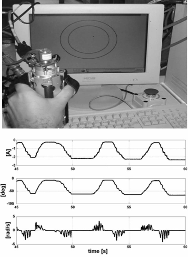
Our initial trial included a very simple interactive game (top, Fig. 10), which is a variation of a pursuit task with the inner circle representing the hand and the outer circle of the goal.
Fig. 10.
Top: simple interactive game. Bottom: graph starting from the top current, grasp angular displacement, and velocity, respectively.
During the game, the system is impedance-controlled resisting movements of the hand with a viscous and elastic force. Fig. 10 shows the displacement, the angular velocity, and the current during one of these tests with unimpaired young subjects. The fact that the velocity drops to zero while the torque is not zero is not due to the impedance controller, but due to human motor behavior.
VI. CONCLUSION
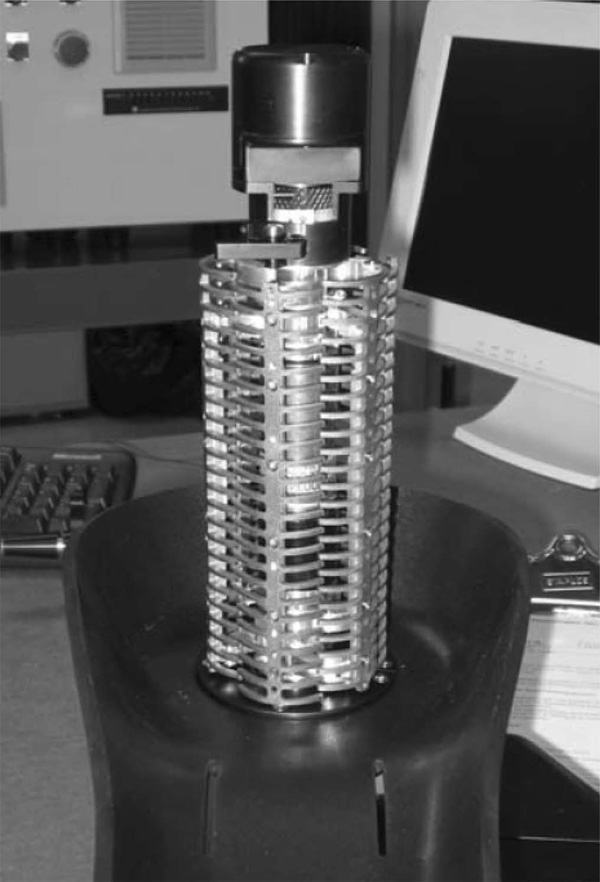
The development and success of MIT-MANUS as a robotic aid for neurorehabilitation has prompted the development of new devices targeting other limb segments and muscle groups often affected by stroke. This paper provides an overview of MIT’s first- and second-hand robot alpha-prototypes. We have started the transition of the second-hand alpha-prototype robot into the clinic. The hand robot is capable of providing sensorimotor training for grasp and release. In its final form (Fig. 11), this device will offer insights into the human motor control and human learning, as well as the potential for tailoring therapy to patients’ needs; and rigorously quantifying outcomes in solo operation or mounted at the tip of the planar, wrist, or antigravity modules or combinations of these to afford, for the first time, a whole-arm functional training [Fig. 4(d)]. Future steps consist of an analysis of the safety of the device in order to use it for clinical trials.
Fig. 11.
MIT hand module final design. Note that the rubber casing was removed to show the mechanism, and that the Velcro bands are not shown, which keep the hand attached to the device during both grasp and release.
VII. DISCLOSURE
Drs. H. I. Krebs and N. Hogan are co-inventors in the MIT-held patent for the robotic device used to treat patients in this paper. They hold equity positions in Interactive Motion Technologies, Inc., the company that manufactures this type of technology under license to MIT.
ACKNOWLEDGMENT
The authors would like to thank the Internationalization Program of Italian Ministry of University and Scientific Research for L. Masia’s stay at MIT.
This work was supported in part by NIH Grant 1 R01-HD045343.
Biography

L. Masia received the M.S. degree in mechanical engineering from the University of Rome “La Sapienza,” Rome, Italy, and the Ph.D. degree in mechanical measurement for engineering from the University of Padua, Padua, Italy, in 2003 and 2007, respectively.
Currently, he is a Postdoctoral Associate at the Robotics, Brain and Congnitive Science Department, Italian Institute of Technology (IIT), Genoa, Italy. He was a Visiting Student at the Massachusetts Institute of Technology in 2005 and 2006, working at the Newman Laboratory for Biomechanics and Human Rehabilitation. His research interests include experimental mechanics, mechanical design, and control of dynamical systems, the development of mechatronic devices to study human–machine interface, and measuring biomechanical data.

Hermano Igo Krebs (M’92–SM’06) received the electrician degree from the Escola Tecnica Federal de Sao Paulo, Sao Paulo, Brazil, in 1976, the B.S. and M.S. degrees in naval engineering from the University of Sao Paulo, Sao Paulo, in 1980 and 1987, respectively, the M.S. degree in ocean engineering from Yokohama National University, Yokohama, Japan, in 1989, and the Ph.D. degree in ocean engineering from Massachusetts Institute of Technology (MIT), Cambridge, in 1997.
From 1977 to 1978, he taught electrical design at the Escola Tecnica Federal de Sao Paulo. From 1980 to 1986, he was a surveyor of ships, offshore platforms, and container cranes at the American Bureau of Shipping, Sao Paulo. In 1989, he was a Visiting Researcher at Sumitomo Heavy Industries, Hiratsuka Laboratories, Japan. From 1993 to 1996, he was with Casper, Phillips and Associates. In 1997, he joined the Department of Mechanical Engineering at MIT, where he is currently a Principal Research Scientist and Lecturer in the Newman Laboratory for Biomechanics and Human Rehabilitation. He is also an Adjunct Professor at the University of Maryland School of Medicine, Department of Neurology, Baltimore, and an Adjunct Assistant Research Professor of neuroscience at Weill Medical College, Cornell University, Ithaca, NY. He is one of the founders of Interactive Motion Technologies—a Cambridge-based start-up company commercializing robot technology for rehabilitation. His research interests include neurorehabilitation, functional imaging, human–machine interactions, robotics, and dynamic systems modeling and control.

P. Cappa received the degree in mechanical engineering (with honors) from the “Sapienza” University of Rome, Rome, Italy in 1980.
He is currently a Full Professor of mechanical measurements with the Department of Mechanics and Aeronautics, “Sapienza” University of Rome, where he was the Head of the Department. He scientifically cooperates with the Movement Laboratory of the Neurorehabilitation Division of IRCCS Pediatric Hospital “Bambino Gesu`,” Rome. His research interests include experimental mechanics applied in biomedical and biomechanical fields.

N. Hogan was born in Dublin, Ireland. He received the Dip. Eng. degree (with distinction) from Dublin College of Technology, Dublin, Ireland, in 1970, and the M.S., M.E., and Ph.D. degrees from the Massachusetts Institute of Technology (MIT), Cambridge, in 1973, 1976, and 1977, respectively.
Currently, he is a Professor of mechanical engineering and a Professor of brain and cognitive sciences at MIT, where he is also the Director of the Newman Laboratory for Biomechanics and Human Rehabilitation. He has also served as the Head and the Associate Head of the System Dynamics and Control Division in the Mechanical Engineering Department at MIT. He is a co-founder of Interactive Motion Technologies, Inc., and a Board Member of Advanced Mechanical Technologies, Inc. His research interests include motor neuroscience, rehabilitation engineering, and robotics.
Prof. Hogan received an Honorary Doctorate from Delft University of Technology, the Silver Medal of the Royal Academy of Medicine in Ireland, and an Honorary Doctorate from Dublin Institute of Technology.
Footnotes
Reprinted from IEEE/ASME Transactions on Mechatronics.
This material is posted here with permission of the IEEE. Such permission of the IEEE does not in any way imply IEEE endorsement of any of this web site's products or services. Internal or personal use of this material is permitted. However, permission to reprint/republish this material for advertising or promotional purposes or for creating new collective works for resale or redistribution must be obtained from the IEEE by writing to pubs-permissions@ieee.org.
By choosing to view this document, you agree to all provisions of the copyright laws protecting it.
Contributor Information
L. Masia, Email: lorenzo.masia@iit.it, Robotics, Brain and Cognitive Science Department, Italian Institute of Technology, 16163 Genoa, Italy..
Hermano Igo Krebs, Email: hikrebs@mit.edu, Department of Mechanical Engineering, Massachusetts Institute of Technology, Cambridge, MA 02139-4307, USA..
P. Cappa, Email: paolo.cappa@uniroma1.it, Department of Mechanics and Aeronautics, “Sapienza” University of Rome, 00184 Rome, Italy..
N. Hogan, Email: neville@mit.edu, Department of Mechanical Engineering and Department of Cognitive Sciences, Massachusetts Institute of Technology, Cambridge, MA 02139-1307 USA..
REFERENCES
- 1.Internet Stroke Center. About stroke. [Online]. Available: http://www.strokecenter.org/pat/about.htm.
- 2.Aisen ML, Krebs HI, McDowell F, Hogan N, Volpe B. The effect of robot assisted therapy and rehabilitative training on motor recovery following a stroke. Arch. Neurol. 1997 Apr.vol. 54:443–446. doi: 10.1001/archneur.1997.00550160075019. [DOI] [PubMed] [Google Scholar]
- 3.Reinkensmeyer DJ, Schmit BD, Rymer WZ. Mechatronic assessment of arm impairment after chronic brain injury. Technol. Health Care. 1999;vol. 7(no 6):431–435. [PubMed] [Google Scholar]
- 4.Krebs HI, Hogan N, Aisen ML, Volpe BT. Robot-aided neurorehabilitation. IEEE Trans. Rehabil. Eng. 1998 Mar.vol. 6(no 1):75–87. doi: 10.1109/86.662623. [DOI] [PMC free article] [PubMed] [Google Scholar]
- 5.Krebs HI, Volpe BT, Aisen ML, Hogan N. Increasing productivity and quality of care: Robot-aided neurorehabilitation. VA J. Rehabil. Res. Develop. 2000;vol. 37(no 6):639–652. [PubMed] [Google Scholar]
- 6.Volpe BT, Krebs HI, Hogan N, Edelstein L, Diels CM, Aisen ML. Robot training enhanced motor outcome in patients with stroke maintained over 3 years. Neurology. 1999;vol. 53:1874–1876. doi: 10.1212/wnl.53.8.1874. [DOI] [PubMed] [Google Scholar]
- 7.Volpe BT, Krebs HI, Hogan N, Edelstein L, Diels CM, Aisen ML. A novel approach to stroke rehabilitation: Robot aided sensorymotor stimulation. Neurology. 2000;vol. 54:1938–1944. doi: 10.1212/wnl.54.10.1938. [DOI] [PubMed] [Google Scholar]
- 8.Volpe BT, Krebs HI, Hogan N. Is robot-aided sensorimotor training in stroke rehabilitation a realistic option? Curr. Opin. Neurol. 2001;vol. 14:745–752. doi: 10.1097/00019052-200112000-00011. [DOI] [PubMed] [Google Scholar]
- 9.Fasoli S, Krebs HI, Stein J, Frontera WR, Hogan N. Effects of robotic therapy on motor impairment and recovery in chronic stroke. Arch. Phys. Med. Rehabil. 2003;vol. 84:477–482. doi: 10.1053/apmr.2003.50110. [DOI] [PubMed] [Google Scholar]
- 10.Fasoli S, Krebs HI, Stein J, Frontera WR, Hughes R, Hogan N. Robotic therapy for chronic motor impairments after stroke: Follow-up results. Arch. Phys. Med. Rehabil. 2004;vol. 85:1106–1111. doi: 10.1016/j.apmr.2003.11.028. [DOI] [PubMed] [Google Scholar]
- 11.Ferraro M, Palazzolo JJ, Krol J, Krebs HI, Hogan N, Volpe BT. Robot aided sensorimotor arm training improves outcome in patients with chronic stroke. Neurology. 2003;vol. 61:1604–1607. doi: 10.1212/01.wnl.0000095963.00970.68. [DOI] [PubMed] [Google Scholar]
- 12.Stein J, Krebs HI, Frontera WR, Fasoli SE, Hughes R, Hogan N. Comparison of two techniques of robot-aided upper limb exercise training after stroke. Am. J. Phys. Med. Rehabil. 2004;vol. 83(no 9):720–728. doi: 10.1097/01.phm.0000137313.14480.ce. [DOI] [PubMed] [Google Scholar]
- 13.Finley MA, Fasoli SE, Dipietro L, Ohlhoff J, MacClellan L, Meister C, Whitall J, Macko R, Bever CT, Krebs HI, Hogan N. Short duration upper extremity robotic therapy in stroke patients with severe upper extremity motor impairment. VA J. Rehabil. Res. Develop. 2005;vol. 42(no 5):683–692. doi: 10.1682/jrrd.2004.12.0153. [DOI] [PubMed] [Google Scholar]
- 14.Daly J, Hogan N, Perepezko E, Krebs HI, Rogers J, Goyal K, Dohring M, Fredrickson E, Nethery J, Ruff R. Response to upper limb robotics and functional neuromuscular stimulation following stroke. VA J. Rehabil. Res. Develop. 2005;vol. 42(no 6):723–736. doi: 10.1682/jrrd.2005.02.0048. [DOI] [PubMed] [Google Scholar]
- 15.MacClellan LR, Bradham DD, Whitall J, Volpe B, Wilson PD, Ohlhoff J, Meister C, Hogan N, Krebs HI, Bever CT. Robotic upper extremity neuro-rehabilitation in chronic stroke patients. VA J. Rehabil. Res. Develop. 2005;vol. 42(no 6):717–722. doi: 10.1682/jrrd.2004.06.0068. [DOI] [PubMed] [Google Scholar]
- 16.Dipietro L, Ferraro M, Palazzolo JJ, Krebs HI, Volpe BT, Hogan N. Customized interactive robotic treatment for stroke: EMG-triggered therapy. IEEE Trans. Neural Syst. Rehabil. Eng. 2005 Sep.vol. 13(no 3):325–334. doi: 10.1109/TNSRE.2005.850423. [DOI] [PMC free article] [PubMed] [Google Scholar]
- 17.Krebs HI, Ferraro M, Buerger SP, Newbery MJ, Makiyama A, Sandmann M, Lynch D, Volpe BT, Hogan N. Rehabilitation robotics: Pilot trial of a spatial extension for MIT-Manus. J. Neuro Eng. Rehabil. 2004;vol. 1(no 5):1–15. doi: 10.1186/1743-0003-1-5. [DOI] [PMC free article] [PubMed] [Google Scholar]
- 18.Hogan N, Krebs HI, Sharon A, Charnnarong J. Interactive robot therapist. Cambridge, MA: Massachusetts Inst. Technol.; 1995. Nov. 14, Tech. Rep. 5 466 213. [Google Scholar]
- 19.Krebs HI, Hogan N, Williams D, Celestino J. Wrist manipulator or system and method for human wrist interface for control of devices, for psychophysical research and for rehabilitation. MIT, Patent pending; [Google Scholar]
- 20.Bouzit M, Burdea G, Popescu G, Boian R. The Rutgers Master II—New design force-feedback glove. IEEE/ASME Trans. Mechatron. 2002 Jun.vol. 7(no 2):256–263. [Google Scholar]
- 21.Takahashi CD, Der-Yeghiaian L, Le VH, Cramer SC. A robotic device for hand motor therapy after stroke. Proc. IEEE 9th Int. Conf. Rehabil. Robot.; Chicago, IL. 2005. Jun./Jul., pp. 17–20. [Google Scholar]
- 22.Kamper DG, Schmit BD, Rymer WZ. Effect of muscle biomechanics on the quantification of spasticity. Ann. Biomed. Eng. 2001 Dec.vol. 29(no 12):1122–1134. doi: 10.1114/1.1424918. [DOI] [PubMed] [Google Scholar]
- 23.Lucas L, DiCicco M, Matsuoka Y. An EMG-Controlled Hand Exoskeleton for Natural Pinching. J. Robot. Mechatron. 2004;vol. 16(no 5):482–488. [Google Scholar]
- 24.Shields BL, Main JA, Peterson SW, Strauss AM. An anthropomorphic hand exoskeleton to prevent astronaut hand fatigue during extravehicular activities. IEEE Trans. Syst., Man, Cybern., A. 1997 Sep.vol. 27(no 5):668–673. doi: 10.1109/3468.618265. [DOI] [PubMed] [Google Scholar]
- 25.Jau BM. Man-equivalent telepresence through four fingered humanlike hand system. Proc. IEEE Int. Conf. Robot. Autom.; Nice, France. 1992. May, pp. 843–848. [Google Scholar]
- 26.Koyama T, Yamano I, Takemura K, Maeno T. Multi-fingered exoskeleton haptic device using passive force feedback for dexterous tele-operation. Proc. IEEE/RSJ Int. Conf. Intell. Robots Syst.; Lausanne, Switzerland. 2002. Oct., pp. 2905–2910. [Google Scholar]
- 27.Rohling RN, Hollerbach JM, Jacobsen SC. Optimized fingertip mapping: A general algorithm for robotic hand teleoperation. Presence: Teleoperators Virtual Environ. 1993;vol. 2(no 3):203–220. [Google Scholar]
- 28.Chao E, et al. Biomechanics of the Hand: A Basic Research Study. Singapore: World Scientific; 1989. [Google Scholar]
- 29.Webb Associates. Anthropometric source book volumeI: Anthropometry for Designers. Yellow Springs, OH: Sci. Tech. Inf. Off.; 1978. [Google Scholar]
- 30.Jugenheimer KL. M.S. Thesis. Cambridge, MA: Massachusetts Inst. Technol.; 2001. Feb., A robot for hand rehabilitation. [Google Scholar]
- 31.Jugenheimer KA, Hogan N, Krebs HI. Proc. ASME IDETC/CIE. Pittsburgh, PA: 2001. Sep., A robot for hand rehabilitation: A continuation of the MIT-MANUS neuro-rehabilitation workstation; pp. 1–7. [Google Scholar]
- 32.Tang P. M. S. Thesis. Cambridge, MA: Massachusetts Inst. Technol.; 2002. Aug., Characterization of a robot designed for hand rehabilitation. [Google Scholar]
- 33.Krebs HI, Masia L. An apparatus and method for converting rotational motion into radial motion. MIT, Patent pending; [Google Scholar]


