Abstract
Quantifying the in vivo interfacial biochemical bond strength of bone implants is a biological challenge. We have developed a new and novel in vivo method to identify an interfacial biochemical bond in bone implants and to measure its bonding strength. This method, named biochemical bond measurement (BBM), involves a combination of the implant devices to measure true interfacial bond strength and surface property controls, and thus enables the contributions of mechanical interlocking and biochemical bonding to be distinguished from the measured strength values. We applied the BBM method to a rabbit model, and observed great differences in bone integration between the oxygen (control group) and magnesium (test group) plasma immersion ion-implanted titanium implants (0.046 versus 0.086 MPa, n=10, p=0.005). The biochemical bond in the test implants resulted in superior interfacial behaviour of the implants to bone: (i) close contact to approximately 2 μm thin amorphous interfacial tissue, (ii) pronounced mineralization of the interfacial tissue, (iii) rapid bone healing in contact, and (iv) strong integration to bone. The BBM method can be applied to in vivo experimental models not only to validate the presence of a biochemical bond at the bone–implant interface but also to measure the relative quantity of biochemical bond strength. The present study may provide new avenues for better understanding the role of a biochemical bond involved in the integration of bone implants.
Keywords: bone–implant interface, interfacial biochemical bond, bonding strength measurement, titanium, metal plasma source ion implantation, surface property
1. Introduction
Our understanding of the contribution of biochemical bonds to successful bone–implant integration is very limited. Therefore, developing an in vivo method to identify an interfacial biochemical bond and to quantify its bonding strength is an outstanding challenge to bone implant science. Pioneering studies reported a direct chemical bonding of ceramic implants to bone (Hench & Paschall 1973; Clark et al. 1976). The possibility of biochemical bonding has been suggested for commercially pure (c.p.) titanium (Albrektsson et al. 1981), titanium alloy (Takatsuka et al. 1995), surface chemistry-modified c.p. titanium (Skripitz & Aspenberg 1998) and hydroxyapatite-coated implants (Edwards et al. 1997). Our recent series of investigations on anion-incorporated (sulphur or phosphorus) and cation-incorporated (calcium or magnesium) titanium implants indirectly verified biochemical bonds in animal models (Sul 2003; Sul et al. 2004, 2005, 2006, 2008).
Many existing methods for evaluating biochemical bonds are qualitative, including electron microscopic observations, bond failure analysis and ion exchange across the bone–implant interface. Quantitative methods such as removal torque tests, push-out tests and ‘detachment’ tests of implants (screws, cylinders and plates) inserted through the bone cortex are involved in the complexity of interfacial stress distributions (Dhert et al. 1992; Brånemark et al. 1998; Brodie et al. 2000), which leads to difficulties in determining the actual bond strength of the bone–implant interface.
Thus, as an alternative approach, tensile pull-off tests using a disc type of implant have emerged as a better method to characterize interfacial bond strength by minimizing shear and friction forces that occur during measurement (Steinemann et al. 1986; Takatsuka et al. 1995; Edwards et al. 1997; Skripitz & Aspenberg 1998; Rønold & Ellingsen 2002). However, the biochemical bonding strength remains essentially unexplored. Major problems with previous methods include the way of stabilizing the functional disc implants in bone and the lack of control of implant surface (IS) properties.
Hence, our aim has been to develop a novel method, named biochemical bond measurement (BBM), to verify interfacial biochemical bonds and to quantify the bonding strength in comparison between the control and test implants. For this purpose, our strategy comprised two major steps. First, we invented devices for pull-off force measurements, called true bond strength (TBS) implants. The present implant devices are new, but have been developed from our 1999 pilot study (Sul 2002). In essence, the device was designed to avoid undesirable friction and shear forces, and thus enable the measurement of the true interfacial bond strength between implant and bone. On the basis of previous findings (Clark et al. 1976; Sul et al. 2005) that interfacial bond failure of the bioactive implants occurs, at least in part, in bone, we defined the extent of true interfacial bonding strength in this study as equivalent to or greater than the bonding strength measured by the TBS implant system. Second, we controlled the similarities and differences in surface properties between the oxygen (control group) and magnesium (test group) plasma source ion-implanted titanium implants, thereby distinguishing the contributions of the biochemical bond strength from the pull-off force measurements. The reason for selecting magnesium titanate surface chemistry for evaluating biochemical bonds is based on our previous findings that electrochemically magnesium-incorporated titanium screw implants resulted in very fast and strong bone integration (Sul et al. 2005, 2006, 2008). To the best of our knowledge, the present study is the first report of an in vivo method for determining the relative quantity of biochemical bonding strength of bone implants.
2. Materials and methods
2.1. Fabrication of the TBS device
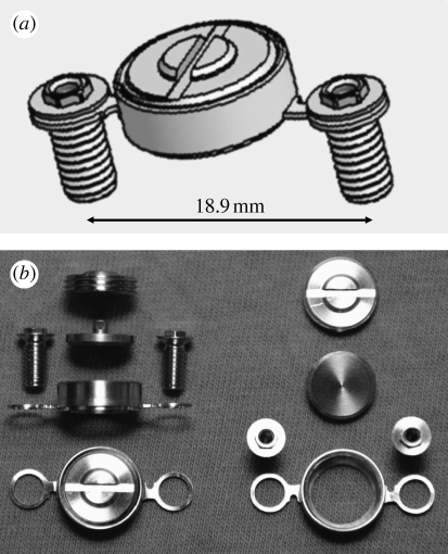
To measure true interfacial bond strength, we first fabricated the TBS implant device, consisting of a functional disc implant, the housing for seating the disc implant, a cover screw and two fixation screws (figure 1; see figure 1 in the electronic supplementary material). All components were custom-made of c.p. titanium (ASTM grade 2) by machine manufacturing. To obtain high-precision quality tissue leak-tight bevel fittings, we performed an additional mill finish on the bevel parts of the disc implant and housing. When assembled, the disc implant was press-fitted into the bevel seat of the housing, preventing tissue ingrowth (soft tissue and bone). Only the functional flat surface of the disc implant should indirectly make contact with the bone. For detailed descriptions of the TBS device, see the electronic supplementary material.
Figure 1.
The TBS implant device. (a,b) The device consists of a disc implant, a housing for settling the disc implant, a cover screw and two fixation screws (for detailed drawings, see figure 1a–e in the electronic supplementary material).
2.2. Surface property design of the functional disc implant
To validate the biochemical bonding effect in bone, we have chosen titanium oxide and magnesium titanate surface chemistry, previously demonstrated to have different bone bonding behaviour (Sul et al. 2005, 2006, 2008). The disc implant was machined, turned and additionally mill-finished for further smoothening of the functional surface. The oxygen-implanted control group (OPIII) and the magnesium-implanted test group (MgPIII) were prepared by plasma immersion ion implantation and deposition (PIII&D; Wood et al. 2000). PIII&D was performed using a metal vapour vacuum arc at a pulse length of 0.3 ms with 3 Hz frequency, an acceleration voltage of 20 kV and an ion dose of 5×10¹⁶ ions cm−2.
The chemical composition of the implants was measured by X-ray photoelectron spectroscopy (XPS; ESCALAB 250, VG Scientific Ltd) using monochromatic Al Kα X-ray source (1486.7 eV, 300 W; the beam size, 400 μm in diameter). The electron take-off angle was fixed at 45° and the vacuum pressure was below 10−9 Torr during spectral data acquisition with a binding energy resolution of 0.1 eV. The compositions of the target elements of Ti, O and Mg atoms were extracted from the Ti 2p3/2 peak (458.8 eV), O 1s peak (530.1 eV) and Mg 1s peak (1305.2 eV) core-level energy regions of the electron orbitals, respectively, using the binding energy of carbon (C 1s: 284.8 eV) as a reference. The surface texture was examined by scanning electron microscopy (LV-SEM; JSM-6380LV, JEOL). The surface roughness was measured using atomic force microscopy (AFM; NTEGRA Probe NanoLaboratory, NT-MDT). There were four measurements for each group with two implants selected and measured at two areas. The measuring area was 50×50 μm for each group.
2.3. Animals and surgical protocol
A total of 10 mature New Zealand white male rabbits were used in this study, which was approved by the local animal ethics committee at the Karolinska Institute, Sweden. The mean weight was 4.4 kg (±0.5) before operation and 4.8 kg (±0.4) at sacrifice, after a 10-week follow-up period. For detailed descriptions of the surgical protocol, see the electronic supplementary material.
2.4. Bone bed preparation and stress-free stabilization of the TBS implant device
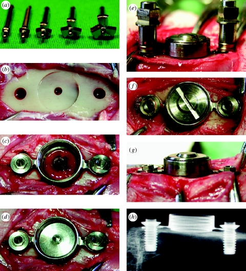
The stress-free stabilization of the device onto bone is necessary for successful bone integration of the disc implant; therefore, it was of practical importance to prepare the bone bed precisely to the dimension of the housing frame. The flat-bottomed bone bed, prepared using custom-made three-flute end mills (figure 2 a,b), played a key role in stabilizing the TBS implant devices by press-fitting with the cylindrical lip of the housing (figure 2 c). The 2 mm diameter bone hole (figure 2 b) was important for the following aspects: keeping a rotation axis in the centre during consecutive milling; facilitating blood supply to the functional surface, where otherwise only minor cortical bone bleeding occurred (figure 2 c); and serving as a marker for evaluating the bone-healing ability of the IS. To securely stabilize the device onto bone, we adapted the device, when necessary, in accordance to the animal's individual variances of the tibia contour by adjusting the necks of the housing arms and allowing for a 0.7 mm tolerance between the diameter of the retention screw and screw hole. The bevel seat of the housing enabled the disc IS to be placed in parallel to the flat-bottomed bone (figure 2 d), which facilitated the cross-head of the pull-off tester to move perpendicularly to the bone–implant interface. We finally secured stress-free stabilization of the TBS implant device to the bone bed by stepwise fastening of the retention screws (figure 2 e–g). An X-ray image confirmed that the TBS implant was installed in the desired place of the bone (figure 2 h).
Figure 2.
Surgical procedure. (a) Custom-made three-flute end mill set. (b) Bone bed preparation for the cylindrical lip of the housing and retention screws. (c) Press-fit stabilization of the housing on the flat-bottomed bone and initial insertion of the retention screws. (d) Bevel-seating of the disc implant on the housing. (e) Assembling of the cover screw and final stepwise fitting of the retention screws. (f,g) Completion of stress-free stabilization of the TBS devices on bone. (h) X-ray image of the TBS devices installed in the tibia.
2.5. Measurement of bonding force
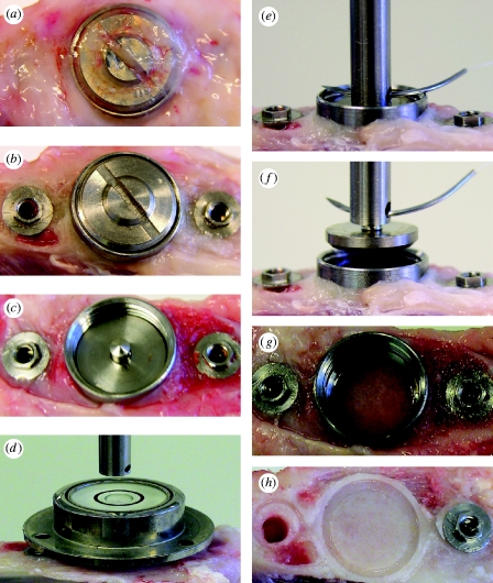
The entire tibia was amputated and immediately fixed in the sample mount of the custom-made pull-off test system (see figure 2 in the electronic supplementary material). The overgrown soft tissue was removed by simply unscrewing the cover screw. The disc implant was then ready to be measured (figure 3 a–c). To optimize alignment for the test, we first connected the hollow cylinder sample holder (female) to the cross-head of the load cell with a 100 mm long wire (0.5 mm in diameter) and allowed it to hang freely (figure 3 d). To avoid lateral loading or bending moments occurring during measurement, we obtained accurate vertical and horizontal alignment between the disc implant and the load cell by using a level tube (figure 3 d) and a three-dimensionally adjustable sample mount at the micrometre scale (see figure 2b in the electronic supplementary material). The sample holder was pin-connected with the cylindrical transducer (male) of the disc implant (figure 3 e; see figure 2c in the electronic supplementary material). The force required to break the interfacial bond was applied by moving the cross-head perpendicularly to the ISs using a constant load rate of 10 mm min−1 (figure 3 f,g). The tester was calibrated with a 10 N load cell. The maximum force obtained was used to determine the interfacial bonding strength.
Figure 3.
Measurement of bonding force. (a–c) The overgrown tissue and cover screw were removed. (d–f) The disc implant was aligned to the central axis of the load cell using the level tube and then coupled to the load cell by means of a pin and pinhole connection. Note (g) no leakage of newly formed bone into the bevel connection between the disc implant and the housing and (h) the newly formed bone underneath the disc IS, showing the replica shape of the cylindrical lip and the offset.
2.6. Statistical analysis
The bond strengths were compared using the Wilcoxon signed-rank test. The statistics program used was an SPSS v. 16. Data are presented as the means±s.d. From the two-tailed significance level (asymptotic two-tailed test), differences were considered statistically highly significant at p≤0.01, statistically significant at p≤0.05 and not significant at p≥0.05.
3. Results
3.1. Ex vivo evaluation of the TBS implant device
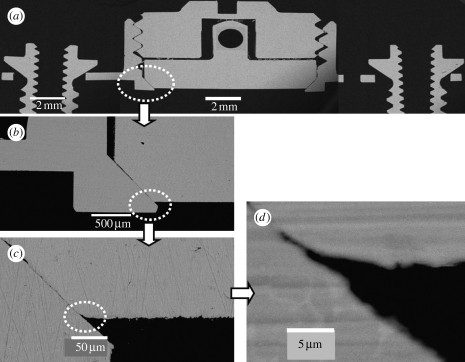
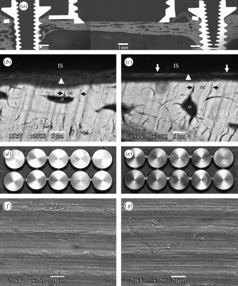
We first evaluated whether the TBS implant devices could be assembled in high-precision quality for measuring TBS (for detailed drawings of the TBS device, see figure 1 in the electronic supplementary material). SEM cross-section observations of the TBS implant assembly embedded in resin (figure 4 a) demonstrated that the disc implant was press-fitted into the bevel seat of the housing by screwing down the cover screw, and that thereby is capable of preventing tissue growth in the chamber. Most importantly, the titanium-to-titanium bevel connection between the disc implant and its housing obtained a good-quality leak-tight fit, with a gap of less than 1 μm (figure 4 b–d). This may prevent bone leakage/ingrowth around the vertical wall of the disc implant, virtually eliminating interfacial friction and shear forces from the measured values. The gap between the vertical walls of the disc implant and the housing chamber (figure 4 b) served as a friction-free pathway for the disc implant during pull-off measurements. A cylindrical lip with an approximately 400 μm outer height (figure 4 b) was fabricated at the bottom part of the housing to enhance stability of the TBS device in the bone fit. To avoid bone resorption occurring underneath the disc implant due to possible stress transmission associated with installation of the devices, we designed the disc implant to be located at the offset position on the bevel seat of the housing. SEM cross-section evaluation (figure 4 b,c) confirmed that the disc IS was approximately 120 μm away (70 μm high inner cylindrical lip +50 μm offset) from the baseline of the housing. This design performance also ensured that the flat surface of the disc implant did not directly come into contact with the old cortex bone bed, but rather with the newly formed bone.
Figure 4.
SEM cross-section view. SEM cross-section observations of the TBS assembly embedded in resin. Note that the disc implant has the functional flat surface with the bevelled flange at the bottom and the cylindrical pin with a hole at the top for connection to the load transducer. (a) The disc implant is positioned in the bevel seat of the housing chamber by fastening the cover screw, the contact between the disc implant and the cover screw is only through the conical apex of the cylindrical transducer of the disc implant. Scale bar, 2 mm. (b) Bevel connection between the bevelled flange of the disc implant and the bevel seat of the housing, 500 μm long. The cylindrical lip of the housing is approximately 70 μm of the inner height and 400 μm of the outer height. Scale bar, 500 μm. Note the clearance between the vertical walls of the disc implant and the housing chamber, a gap of approximately 80 μm, ensuring no occurrence of friction during pull-off movement of the disc implant. (c) Bevel offset, approximately 50 μm. Scale bar, 50 μm. (d) High magnification of the titanium-to-titanium bevel seat fitting shows a leak-tight connection, with a gap of less than 1 μm. Scale bar, 5 μm.
3.2. Control of the surface properties
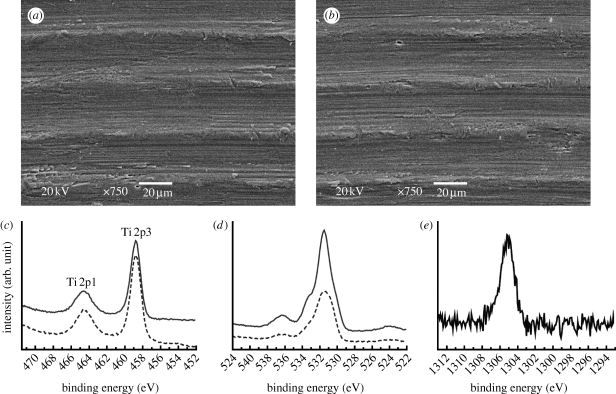
To distinguish the contributions of mechanical interlocking and biochemical bonding from the measured strength values, we controlled the surface properties of the involved implants. SEM micrographs showed nearly identical surface texture between the control and test implants (figure 5 a,b). AFM measurements at 50×50 μm showed only minor differences in the surface roughness values, with slightly higher values of the control surface for all the parameters measured. The surface chemistry showed a clear difference in the representative elements between the O 1s core-level energy regions of the electron orbital at 531 eV for the control implants and the Mg 1s core-level energy regions at 1305.2 eV for the test implants, as detected by high-resolution XPS (figure 5 c,d). Relative Mg atom concentration was approximately 5 at%. Control of the surface properties of the implants is summarized in table 1.
Figure 5.
Surface property control. (a,b) The similarity of the surface topography: SEMs show nearly identical texture between (a) the control and (b) test implants, characterized by uniformly orientated margin and grooves, having a wavelength of approximately 30 μm. Scale bar, 20 μm. (c–e) The difference of surface chemistry: XPS high-resolution spectra showed the peak intensities of (c) the Ti 2p3/2 at 458.8 eV and (d) the O 1s at 530.1 eV for the control (solid line) and test (dashed line) implants, respectively, and (e) the peak intensity of the Mg 1s at 1305.2 eV for the test implants.
Table 1.
Control of the surface properties of the implants. (Roughness parameters measured by AFM at 50 μm×50 μm, measurement number (n)=4: Sa, arithmetic average of height deviation; Sq, root mean square of height deviation; Ssk, asymmetry of height distribution; Sdr, increment of the interfacial surface area relative to the area of the projected x, y plane.)
| surface property | OPIII (control) implant | MgPIII (test) implant |
|---|---|---|
| chemical composition | mainly TiO2 contaminant, C | mainly TiO2 and Mg≤5%; contaminant, C |
| surface texture | rotation-oriented margin and groove; wavelength≈35 μm | rotation-oriented margin and groove; wavelength≈35 μm |
| roughness | Sa 0.27 (±0.04) μm | Sa 0.24 (±0.02) μm |
| Sq 0.33 (±0.05) μm | Sq 0.29 (±0.03) μm | |
| Ssk 0.36 (±0.24) | Ssk 0.19 (±0.23) | |
| Sdr 6.1 (±2.6)% | Sdr 5.5 (±1.6)% |
3.3. Validity of the TBS implant device and controlled surface properties for quantification of biochemical bonds
Each of the 20 TBS devices (10 of each group) was successfully integrated in bone with no tissue invasion in the chamber after a healing period of 10 weeks (figure 3 a–c). The bond strength was measured by a custom-made pull-off test system (figure 3 d–f; see figure 2 in the electronic supplementary material). Each individual test implant showed higher bond strength than the control implant paired in the same animal (see table 1 in the electronic supplementary material). The mean values demonstrated a highly significant difference between 0.046 MPa (±0.009) for the control group (n=10) and 0.086 MPa (±0.02) for the test group (n=10) (p=0.005). Notably, the control and test surfaces showed different abilities to heal the 2 mm bone defect. In the control surfaces, 3 out of 10 hole defects remained unclosed (figure 6 a) or showed a network formation of soft tissue and woven bone (figure 6 b). By contrast, all the test surface defects were repaired with bone formation (figures 3 h and 6 c). As was predicted from the ex vivo evaluation, the titanium-to-titanium bevel fit between the disc implant and its housing was tight enough to prevent bone leakage. There was neither bone growth along the vertical wall of the disc implant (figure 3 c) nor visible bone ingrowth on the bevel seat of the housing (figure 3 g). Only the flat functional surface of the disc implant was allowed contact with the newly formed bone, evident from comparing the bone level at surgery (figure 2 b) and after measurement (figure 3 h). Overall, these data indicate that the friction and shear strengths against the vertical wall of the disc implant during pull-off force measurement were virtually eliminated.
Figure 6.
Healing state of the bone hole defect (2 mm wide) underneath the disc ISs after 10 weeks of healing time. (a,b) Uncompleted bone union of the hole defect with the control surface. (c) Sufficient bone formation for union of the defect with the test surface.
To verify that TBS implant devices measured true interfacial bond strengths, we evaluated whether the mode of bond failure was due to true interfacial failure between the implant and bone tissue or cohesive failure in the layer of bone tissue bordering the interface (figure 7). SEM observations showed that bond failure generally occurred between the ISs and tissues consisting of an amorphous layer of woven bone growing upon mature bone (figure 7 a–c). This amorphous layer in contact with the test IS regularly contained mineralized tissues, as evidently indicated by electron-dense deposits, in the interface very close to the implant. This was not the case in the control IS. In addition, the amorphous layer of the test IS appeared much thinner than that of the control surface. Consequently, the test surface showed shorter contact distance to mature bone than the control surface. These qualitative observations validated the quantitative measurements of interfacial bond strength above. In general, the mechanical interlocking theory suggests that mechanical interlocking of the implant to bone tissues occurs only when tissues grow into pores, holes, cavities and other irregularities and lock mechanically to the IS. The pull-off forces are known to correlate with the surface roughness at nano- and microscales (Beach et al. 2002; Rønold & Ellingsen 2002; Jang et al. 2007). However, surface analysis of the retrieved implant confirmed that bone growth into surface irregularities was barely detected in both the control and test implants (figure 7 d–g). Furthermore, differences in mechanical interlocking strength between the control and test implants, if any, were negligible since the surface textures were nearly identical and roughness values were similar. Altogether, these data provide validity for the TBS implant device to measure true interfacial bond strength. Furthermore, the data suggest that, beyond mechanical interlocking, enhancement of interfacial bond strength in the test implants may have resulted from the biochemical bond of magnesium-implanted surface chemistry.
Figure 7.
Fracture analysis of the bone–implant interface after the pull-off test. (a) SEM observation of a cross section of the TBS device in bone. SEM observation on the bone side removed from (b) the control (OPIII) and (c) test (MgPIII) surfaces. Bond failure occurs between the ISs (removed by the pull-off measurement) and tissue represented by an amorphous layer of woven bone (arrow head). The amorphous layer between the (removed) IS and fully mineralized mature bone showed different behaviour for the control and test ISs: (i) the contact distance of the IS to the mature bone, i.e. the thickness of the amorphous layer, and (ii) the degree of mineralization. In the test surface, the amorphous layer is rather thin and shows more pronounced mineralization, indicated by the backscattered electron-dense lines of approximately 2 μm width (white arrow) close to the IS, whereas the control surface contacts the thick amorphous layer without the electron-dense tissue line. In the fully mineralized mature bone, osteocytes (o) are adjacent to the amorphous layer and the osteocyte canaliculi (oc, black arrow) direct to the IS. Electron beam exposure in the imaging BSE mode, 15 kV. Scale bars, 5 μm. (d–g) Analysis of the retrieved ISs. No bone growth onto (d,f) all the control surfaces and (e,g) the test surfaces, 10 of each group, is observed. Scale bars, 20 μm. Note that the retrieved implants still have similar surface texture as shown in figure 5 a,b prior to bone contact.
3.4. Determination of the relative quantity of biochemical bond strength
To calculate the biochemical bond strength of the test implant relative to the control implant, we used the following equation. It was assumed that interfacial bond strength measured with the BBM method involved biochemical bonding, mechanical interlocking and friction force,
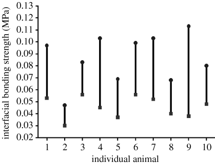
Here, ΔCBt–c (CBt–CBc) is the relative quantity of biochemical bond strength of the test to control implant, and BSt and BSc are the bond strength measured by the TBS system for the test and control implants, respectively. MBt and MBc, FFt and FFc are the strengths of the mechanical interlocking and friction forces inherent to the surface roughness for the test and control implants, respectively. Our results imply that both (MBt–MBc) and (FFt–FFc) are close to zero. Therefore, we simplified the equation to ΔCBt–c≈(BSt–BSc), stating that the relative quantity of biochemical bond strength can be approximated by subtraction between the measured bond strengths of the test and control implants. The relative biochemical bond strength of individual animals was plotted (figure 8).
Figure 8.
Validation of the relative quantity of biochemical bond strength. Difference between interfacial bond strengths, ΔBS=BSt–BSc, always shows a positive value with statistically high significance (p=0.005). The relative quantity of the biochemical bond strength, ΔCBt–c≈(BSt–BSc), shows a mean value of 0.04 MPa. BSt and BSc are the bond strengths of the test (circles, MgPIII) and control (squares, OPIII) implants, respectively. The individual values of ΔCBt–c, BSt and BSc are shown in table 2 in the electronic supplementary material.
4. Discussion
To measure true interfacial bond strength, it was imperative to fabricate the implant devices to virtually eliminate friction and shear forces and to ensure stress-free stabilization of the functional disc implant to the bone. Control of the functional disc implant's surface properties is also a key parameter in determining the relative contribution of biochemical bond strength from interfacial bond measurements. The current results are in good agreement with our previous studies which found that the magnesium titanate surface chemistry of implants elicits superior bone integration compared with control implants despite their low roughness values (Sul et al. 2005, 2006, 2008).
The BBM method demonstrates several advantages over existing approaches. The principal advantage is that TBS implant devices achieve a very high success rate of bone integration, providing a necessary condition for assessing true interfacial bond strength. A 100 per cent success rate of bone integration with the TBS implants is of great significance when compared with only 60–72% integration with previous methods (Edwards et al. 1997; Skripitz & Aspenberg 1998; Rønold & Ellingsen 2002). This outstanding success rate most probably results from the excellent design performance of the TBS implant device and the stabilization of the functional disc implant onto bone. The leak-tight bevel fittings played an important role in preventing bone ingrowth, virtually eliminating friction and shear strength against the vertical wall of the disc IS. In addition, the fittings blocked the pathway of stress transmission through the disc implant to bone, which prevents the bone resorption underneath the disc implants related to installation of the devices in bone, although a certain amount of bone resorption by surgical trauma is inevitable. Furthermore, by applying the titanium-to-titanium bevel connection, the BBM method rules out a central concern from previous methods that wrapping of the titanium disc (or coin) implants with non-metallic materials such as silicone rubber (Steinemann et al. 1986), silastic tubing ring (Edwards et al. 1997) and polytetrafluoroethylene cap (Rønold & Ellingsen 2002) may cause galvanic currents due to their volta-potential differences and, consequently, affect bone tissue function and compactness (Izabakarov & Markov 1993; Leng et al. 1999). The BBM method guarantees no bone resorption underneath the disc implant. By contrast, previous methods used ‘elastic flexture’ of the bone plate alone or together with a spring over the top of the disc implants to stabilize the disc (coin) implant on bone. This elastic flexture and ‘spring action’ have a risk of provoking bone resorption to some extent under the disc implant until they will last long.
The second advantage is that TBS implant devices are easily assembled at surgery and the disc implant, protected in the housing chamber, is safely and quickly exposed for measurement by simply unscrewing the cover screw. Unlike previous methods, the BBM method needs neither ‘gentle’ removal of the bone plate/spring nor ‘careful’ removal of the wrapping materials (Steinemann et al. 1986; Edwards et al. 1997; Rønold & Ellingsen 2002) of the disc implants, which implies a risk of fracturing the interfacial bond prior to measurements. The TBS implant secures optimum alignment of the central axis of the disc implant and the cylindrical transducer as they were fabricated in one body by rotation-symmetrical machining, which avoids shear and tilting forces, whereas previous methods attached an additional transducer, by screwing or adhesives, to the top side of the disc implant during measurements (Steinemann et al. 1986; Edwards et al. 1997; Rønold & Ellingsen 2002).
Last but most importantly, the TBS method takes advantage of precisely controlling surface properties, enabling the relative contribution of biochemical bond strengths to be determined from interfacial bond measurements. In previously used models, different surface engineering methods were used for the control and test surfaces; hence, it is uncertain which surface properties contributed to the measured bond strength (Takatsuka et al. 1995; Edwards et al. 1997; Skripitz & Aspenberg 1998).
On the interfacial tensile strength of very smooth ISs in bone such as Sa 0.2 μm of the present study, few literature data are available for comparisons. Moreover, the values of tensile strength differed from study to study: 0.01 MPa for the sandpaper-polished titanium surfaces with a roughness of Ra=0.48 μm in rat tibiae after a healing time of four weeks, where the tensile strength never exceeded 0.03 MPa (Skripitz & Aspenberg 1998); 0.11 MPa for the grit-blasted titanium surfaces with a roughness of Sa 1.12 μm in rabbit tibiae after eight weeks (Rønold et al. 2003); and 1–4.1 MPa for the sand-blasted or sand-blasted and titanium-plasma-coated titanium surfaces with a roughness depth of approximately 20 μm in monkey ulnae after 100 days (Steinemann et al. 1986). The variations of the tensile strength in the literature could partly be explained by the fact that not only surface treatments, control of the surface properties and quality of the tensile implant devices in contact (indirect contact, gap model in the present study or direct contact mode in the other studies) with bone as discussed above, but also healing time, animal species and implant site influence the tensile strength of the bone–implant interface.
One idea for better quantification of biochemical bonds in vivo is to investigate the bone integration of ‘perfectly’ smooth surfaces, while varying the surface chemistry. Following this idea, we have performed a pilot study using the electropolished, very smooth surfaces of approximately 7 nm in Sa (arithmetic average of height deviation), with the same experimental protocols as the current study. Of the 20 TBS devices installed in 10 animals, however, seven disc implants could not be considered for interfacial bond strength because of bone leakage between the bevel connection of the disc implant and the housing. The 13 remaining implants showed similar trends in bond strengths to the present results. The reason for the bone leakage was that electrochemical dissolution of the bevel edge of the disc implants by electropolishing impaired precision of the leak-tight connection. This pilot study is a reminder that, for measurement of true interfacial bond strength, it is of great importance to prevent bone leakage along the vertical wall of the disc implant to ensure the functional flat surface is solely in contact with the bone.
Although it is extremely difficult to validate a biochemical bond in vivo and determine its strength, the new BBM method can help improve the limited understanding of the role of biochemical bonding in implant integration and facilitate further development of bone implants to improve clinical performance.
5. Conclusions
We have developed a new and novel in vivo method to validate the presence of an interfacial biochemical bond at the bone–implant interface and to measure the relative quantity of biochemical bond strength. This method involves a combination of the implant devices to measure true interfacial bond strength and surface property controls of the implants, and thus enables the biochemical bond strength to be distinguished from the measurements. As demonstrated in the test implants, the biochemical bond resulted in superior interfacial behaviour of the implants to bone: (i) close contact to approximately 2 μm thin amorphous interfacial tissue, (ii) pronounced mineralization of the interfacial tissue, (iii) rapid bone healing in contact, and (iv) strong integration to bone. The present study may provide key knowledge not only for a better understanding of the role of a biochemical bond involved in integration of bone implants but also for development of bone implants to improve clinical performance.
Acknowledgments
The research was supported by a research grant from the Biotechnology Development Project (2007-04306) from the Ministry of Education and Human Resource Development, Republic of Korea. We thank J.-K. Kim and E. Byon (Korea Institute of Machinery and Materials, Korea) for providing PIII&D. We also thank Thay. Q. Lee (University of California, Irvine, USA) for critical reading of the manuscript.
References
- Albrektsson T., Branemark P. I., Hansson H. A., Lindstrom J.1981Osseointegrated titanium implants. Requirements for ensuring a long-lasting, direct bone-to-implant anchorage in man. Acta Orthop. Scand. 52 155–170. 10.3109/17453678108991776 [DOI] [PubMed] [Google Scholar]
- Beach E. R., Tormoen G. W., Drelich J., Han R.2002Pull-off force measurements between rough surfaces by atomic force microscopy. J Colloid Interface Sci. 247 84–99. 10.1006/jcis.2001.8126 [DOI] [PubMed] [Google Scholar]
- Brånemark R., Ohrnell L. O., Skalak R., Carlsson L., Brånemark P. I.1998Biomechanical characterization of osseointegration: an experimental in vivo investigation in the beagle dog. J. Orthop. Res. 16 61–69. 10.1002/jor.1100160111 [DOI] [PubMed] [Google Scholar]
- Brodie E. M., Yuehuei H. A., Richard J. F.2000Factors affecting the strength of the bone–implant interface Mechanical testing of bone and the bone implant interface Yuehuei H. A., Draughn R. A.439–462London, UK: CRC Press. [Google Scholar]
- Clark A. E., Hench L. L., Paschall H. A.1976The influence of surface chemistry on implant interface histology: a theoretical basis for implant materials selection. J. Biomed. Mater. Res. 10 161–174. 10.1002/jbm.820100202 [DOI] [PubMed] [Google Scholar]
- Dhert W. J. A., Verheyen C. C. P. M., Braak L. H., De Wijn J. R., Klein C. P. A. T., de Groot K., Rozing P. M.1992A finite element analysis of the push-out test: influence of test conditions. J. Biomed. Mater. Res. 26 119–130. 10.1002/jbm.820260111 [DOI] [PubMed] [Google Scholar]
- Edwards J. T., Brunski J. B., Higuchi H. W.1997Mechanical and morphologic investigation of the tensile strength of a bone hydroxyapatite interface. J. Biomed. Mater. Res. 36 454–468. 10.1002/(SICI)1097-4636(19970915)36:4%3C454::AID-JBM3%3E3.0.CO;2-D [DOI] [PubMed] [Google Scholar]
- Hench L. L., Paschall H. A.1973Direct chemical bond of bioactive glass–ceramic materials to bone and muscle. J. Biomed. Mater. Res. 7 25–42. 10.1002/jbm.820070304 [DOI] [PubMed] [Google Scholar]
- Izabakarov I., Markov B. P.1993The effect of dissimilar metals (galvanic current) on bone tissue status. Stomatologiia (Mosk). 72 19–22. [PubMed] [Google Scholar]
- Jang J., Sung J., Schatz G. C.2007Influence of surface roughness on the pull-off force in atomic microscopy. J. Phys. Chem. C. 111 4648–4654. 10.1021/jp066667a [DOI] [Google Scholar]
- Leng A., Streckel H., Hofmann K., Stratmann M.1999The delamination of polymeric coatings from steel. Part 3: effect of the oxygen partial pressure on the delamination reaction and current distribution at the metal/polymer interface. Corros. Sci. 41 599–620. 10.1016/S0010-938X(98)00168-1 [DOI] [Google Scholar]
- Rønold H. J., Ellingsen J. E.2002Effect of micro-roughness produced by TiO2 blasting—tensile testing of bone attachment by using coin-shaped implants. Biomaterials. 23 4211–4229. 10.1016/S0142-9612(02)00167-9 [DOI] [PubMed] [Google Scholar]
- Rønold H. J., Lyngstadaas S. P., Ellingsen J. E.2003A study on the effect of dual blasting with TiO2 on titanium implant surfaces on functional attachment in bone. J. Biomed. Mater. Res. A. 67 524–530. 10.1002/jbm.a.10580 [DOI] [PubMed] [Google Scholar]
- Skripitz R., Aspenberg P.1998Tensile bond between bone and titanium: a reappraisal of osseointegration. Acta Orthop. Scand. 69 315–319. 10.3109/17453679809000938 [DOI] [PubMed] [Google Scholar]
- Steinemann S. G., Eulenberger J., Maeusli P.-A., Schroder A.1986Adhesion of bone to titanium Biological and biomechanical performance of biomaterials eds Christel P., Meunier A., Lee A. J. C.409–414 Amsterdam, The Netherlands: Elsevier Press. [Google Scholar]
- Sul Y.-T. 2002. On the bone response to oxidized titanium implants: the role of microporous structure and chemical composition of the surface oxide in enhanced osseointegration. Thesis, Department of Biomaterials/Handicap Research, University of Gothenburg, Sweden.
- Sul Y.-T.2003The significance of the surface properties of oxidized titanium implant to the bone response: special emphasis on potential biochemical bonding of oxidized titanium implants. Biomaterials. 24 3893–3907. 10.1016/S0142-9612(03)00261-8 [DOI] [PubMed] [Google Scholar]
- Sul Y.-T., Byon E., Jeong Y.2004Biomechanical measurements of calcium-incorporated, oxidized implants in rabbit bone: effect of calcium surface chemistry of a novel implant. Clin. Implant. Dent. Relat. Res. 6 101–110. 10.1111/j.1708-8208.2004.tb00032.x [DOI] [PubMed] [Google Scholar]
- Sul Y.-T., Johansson C., Byon E., Albrektsson T.2005The bone response of oxidized bioactive and non-bioactive titanium implants. Biomaterials. 26 6720–6730. 10.1016/j.biomaterials.2005.04.058 [DOI] [PubMed] [Google Scholar]
- Sul Y.-T., Johansson C., Albrektsson T.2006Which surface properties enhance bone response to implants? Comparison of oxidized Mg implant, TiUnite and Osseotite surfaces. Int. J. Prosthodont. 19 319–329. [PubMed] [Google Scholar]
- Sul Y.-T., et al. 2008The role of surface chemistry and surface topography of osseointegrated titanium implant: strength and rate of osseointegration J. Biomed. Mater. Res. A ( 10.1002/jbm.a.32041) [DOI] [PubMed]
- Takatsuka K., Yamamuro T., Nakamura T., Kokubo T.1995Bone-bonding behavior of titanium alloy evaluated mechanically with detaching failure load. J. Biomed. Mater. Res. 29 157–163. 10.1002/jbm.820290204 [DOI] [PubMed] [Google Scholar]
- Wood B. P., Rej D. J., Anders A., Brown I. G., Faehl R., Malik S. M., Munson C. P.2000Fundamentals of plasma immersion ion implantation and deposition Handbook of plasma immersion ion implantation and deposition ed Andres A.243–301New York, NY: Wiley-Interscience Press. [Google Scholar]


