

Abstract
Surface topography is well known to play a crucial role in influencing cellular responses to an implant material and is therefore important in bone tissue regeneration. A novel jet-based patterning technique, template-assisted electrohydrodynamic atomization spraying, was recently devised to control precisely the surface structure as well as its dimensions. In the present study, a detailed investigation of this patterning process was carried out. A range of nano-hydroxyapatite (nHA) line-shaped patterns <20 µm in width were successfully deposited on a commercially pure Ti surface by controlling the flow of an nHA suspension in an electric field. In vitro studies showed that the nHA patterns generated are capable of regulating the human osteoblast cell attachment and orientation.
Keywords: surface topography, hydroxyapatite, nanoparticles, template-assisted, electrohydrodynamic, spraying
1. Introduction
Since the 1980s, hydroxyapatite (Ca10(PO4)6(OH)2; HA) has been used as a coating material for orthopaedic implant applications owing to its bioactivity and similarity in composition to bone mineral (Constantz et al. 1995). It was found to be capable of supporting bone ingrowth and osseointegration (Hench 1998). Therefore, it had significant success in strengthening the fixation between the implant and bone tissue, thus reducing the healing period during orthopaedic implantation practice (Oonishi 1991).
However, in addition to surface chemistry, a number of studies have shown that the surface topography can be another significant factor in influencing the initial cellular response and therefore subsequent bone tissue regeneration (Curtis & Wilkinson 1997). The work of Britland et al. (1996) compared a chemical cue (laminin) oriented at right angles with a topographic factor. When the grooves were <500 nm deep, the cells reacted mainly with the chemical cue. When deeper grooves were present, the topographic cue was more significant than the chemical type, and, at 5 µm depth, the topographic effect oriented approximately 80 per cent of the cells and the chemical type 7 per cent. It was also found that cell alignment was profoundly enhanced on all surfaces that presented both cues in parallel. Furthermore, the cells were able to switch alignment from ridges to grooves depending on the location of superimposed adhesive tracks, which implies that the cellular orientation is significantly influenced by not only the structure but also the dimension (Clark et al. 1987). It is apparent that cellular responses to materials depend on structural properties of the material at both the micrometre (Brunette & Chehroudi 1999) and nanometre scales (Webster et al. 2000; Wilkinson et al. 2002). However, general methods for processing and controlling three-dimensional biomaterial surface properties on both the scales are still lacking.
In recent years, several studies have been carried out on processing three-dimensional structures on the substrate surfaces for biomedical applications. Techniques such as etching (Tan & Saltzman 2004), ink-jet printing (Roda et al. 2000) and electrohydrodynamic three-dimensional printing (Ahmad et al. 2006) have been widely used to create biomaterials with three-dimensional topography. However, these techniques suffer significant limitations. For instance, etching is normally used to create ordered surface structure on relatively ductile materials such as polymeric and metallic materials (Le Guehennec et al. 2007). It is difficult to use etching methodologies for brittle and chemically stable ceramics such as HA. At present, it is still difficult to use direct printing techniques to create precise small-dimensional surface structures. The three-dimensional patterns printed are normally of 50–100 µm in size (Roda et al. 2000; Ahmad et al. 2006), which is large compared with the dimension of osteoblasts (approx. 40 µm).
More and more attention has been paid to surface patterning techniques that require an assisting mask during the deposition process, e.g. pulsed-laser deposition (Peruzzi et al. 2004), template-assisted ion beam sputtering (Puckett et al. 2008), photo-immobilization process (Barbucci et al. 2003) and mask-assisted electrochemical micromachining (Kern et al. 2007). Thus metallic, ceramic and polymeric microscale, well-defined patterns can be achieved for different applications using such techniques. However, the drawbacks of these laser beam and electrochemistry-type deposition techniques are high processing cost, low deposition efficiency and complexity of the procedures required, and these lead to actual difficulties for their application in the healthcare industry. Thus, the recently reported patterning technique, called template-assisted electrohydrodynamic atomization (TAEA) spraying (Li et al. 2008), is of considerable interest owing to the range of advantages it offers, such as high deposition efficiency, easy setup, low cost and high resolution.
The TAEA process, introduced in our previous brief report (Li et al. 2008), evolves from electrohydrodynamic atomization spraying (EHDA) and uses novel ground electrode configurations and templates. It is a process that can deposit microscale features (few micrometres) of nanosize particles. EHDA is a well-documented deposition technique used for various applications. In principle, it consists of a nozzle (needle) connected to a high-voltage supply and a ground electrode. A suspension or liquid containing the functional material to be deposited is fed to the nozzle, kept at a high voltage, at a controlled flow rate. The jet and droplets generated are classified into different modes of spraying by the geometries of the jet (Jaworek & Krupa 1999). Out of several different modes, the cone-jet mode, which is the steadiest mode of spraying, could regularize the break-up of jet to generate fine and uniform droplets of a few micrometres in size. In TAEA, droplets are driven by the electrical force to attach to the substrate as well as on top of the template.
After evaporation of the solvent or liquid carrier, the deposited material particles distribute uniformly on the substrate and template. By removing the template, a deposition of well-defined patterns can be achieved on the substrate surface (Li et al. 2008). As a jet-based patterning technique, the dimension of the patterns largely depends on the spacing size in the template. A template with a small spacing size can lead to patterns with small dimensions. However, another striking factor is the droplet size produced after jetting. To create a precise high-resolution HA pattern, it has to be ensured that the nano-HA (nHA) suspension droplets can be small enough to pass through the tiny spacing of the template and attach to the targeted substrate. Furthermore, after the suspension droplets attach to the substrate, their spreading can also lead to coarse edges of the patterns. Therefore, the reduction of the droplet size and the control of the droplets spreading on the substrate become the major challenges in controlling this process. Owing to the nature of electrohydrodynamic spraying, the liquid droplets form after the jet break-up and travel to the actual target substrate. Increasing the substrate surface temperature could accelerate solvent evaporation and reduce the deposited relic size without causing any other complexities during the patterning. Therefore, in this study, the Ti substrates were held at different temperatures to control the spreading of nHA suspension droplets on the substrate surface. In vitro studies were also carried out on deposited nHA patterns of different widths to investigate human osteoblast (HOB) cellular orientation.
2. Material and methods
2.1. Nano-hydroxyapatite suspension preparation and characterization
nHA was synthesized by a precipitation reaction between calcium hydroxide and orthophosphoric acid. All reagents were AnalaR grade (Sigma-Aldrich, Poole, UK). Orthophosphoric acid of concentration 0.3 M was added drop-wise to a 0.5 M calcium hydroxide solution under continuous stirring at ambient temperature (25°C), while the pH was kept above 10.5 by the addition of ammonium hydroxide solution. Stirring was maintained for a further 16 h after complete addition of the reactants. The precipitate obtained was aged for a further week and then washed with boiling water. The morphology of the nHA particles was examined using a JEOL 200CX transmission electron microscope (TEM) using an accelerating voltage of 200 keV, and the size distribution of the nHA particles was investigated by analysing TEM micrographs. The structure of the nHA was analysed using a Phillip X-ray diffractometer operating at 40 kV and 40 mA in the scanning range of 25–50° with a step size of 0.05° and a scan time of 6 s.
The aged nHA particles were then taken up in ethanol (Sigma-Aldrich) to prepare nHA suspensions containing 6 wt% of nHA particles. The mixing process was carried out using a Branson 250 sonificator. The exact nHA content in the suspension was determined by loss-on-ignition.
Characterization of the suspensions involved measurements of electrical conductivity, density and surface tension for nHA suspensions and ethanol for comparison. Conductivity was measured using a HANNA H1 8733 conductivity meter. Density was calculated using a standard density bottle (25 ml). Surface tension was measured using a Kruss K9 Tensiometer, using the plate mode. In each, the equipment used was calibrated with a standard liquid and measurement was repeated several times to obtain a mean value.
Further details of suspension preparation and characterization of the nHA particles and suspension are described elsewhere (Li et al. 2007).
2.2. Template-assisted electrohydrodynamic atomization spraying
The TAEA equipment layout used in this work is illustrated in figure 1a. The stainless steel needle used had an inner diameter of approximately 300 µm. Freshly prepared nHA suspension was syringed to the needle at flow rates of 10 µl min−1 with the applied voltage between the needle and the ground electrode varied up to 6 kV to investigate electrohydrodynamic spraying scenarios. As shown in figure 1b, a specifically designed ground electrode configuration was used for the TAEA process. The grounded hot plate was placed at the bottom to control the substrate temperature. It was covered with a silicon wafer, on top of which the actual Ti substrate was kept. The distance between the stainless steel needle and substrate was fixed at 40 mm. Commercially pure titanium substrate plates were polished using P4000 silicon carbide grinding paper to ensure similar surface roughness and subsequently cleaned using acetone and ethanol. This is important as surface roughness and wetability will influence the results of this investigation as will the chemical nature of the substrate. During the patterning process, the substrates were heated to 40°C and 80°C (the boiling point of ethanol solvent is approx. 78°C), and the spraying time was controlled at 30 s. A range of gold templates with similar grid spacings were used to mask the Ti substrate during patterning.
Figure 1.

(a) Schematic illustrating the nHA deposition by an electrohydrodynamic route and (b) electrode configurations employed for the patterning process.
2.3. Characterization of nano-hydroxyapatite deposits
The morphology of the HA relics and patterns on the Ti substrate were examined using a field emission scanning electron microscope (FE-SEM, JEOL JSM/6301F). For FE-SEM, the working distance was 15 mm and the accelerating voltage was set at 15 kV. The dimensions of the patterns were characterized by measuring on SEM micrographs. The measurements of each pattern were carried out at 25 different locations to ensure accuracy.
The pattern topographies were also determined using a Tracor Northern model-IE tandem scanning-reflected light microscope equipped with a rotating Nipkow disc with 60 µm holes, illuminating the specimen with a 100 W mercury light source (Nikon). Baseline images were obtained using a tandem scanning confocal microscope (Noran Instruments, Middleton, WI, USA) with an oil immersion lens (× 100, NA 1.6). The peak-to-baseline (Z height) measurements were taken with a confocal microscope using an extended focus image stage. Ten replicates were obtained per surface pattern examined.
2.4. In vitro study
For cell-based assays, nHA-patterned substrates were sterilized using 70 per cent (v/v) ethanol prior to use and were air-dried in a class II cabinet to maintain sterility. Passaged alveolar HOBs (passage number less than 6) were obtained from patients undergoing routine third molar extraction using an isolation method reliant on the differential migration of cells from the explanted bone fragments (Di Silvio & Gurav 2001). The samples were obtained from four donors aged less than 40 years. Ethical approval and written consent were obtained. Briefly, the bone chips were cultured under sterile conditions until osteoid seams were seen and then digested using collagenase (100 U ml−1) and trypsin (300 U ml−1) solutions.
Cells obtained in this way were cultured in 25 cm2 tissue culture flasks at 37°C, under 95 per cent relative humidity and 5 per cent CO2 until approximately 80 per cent confluency was achieved. The culture medium used was Dulbecco's minimal essential medium, supplemented with 10 per cent foetal calf serum, 5 ml of non-essential amino acids, 75 µg ml−1 ascorbic acid, 20 mM l-glutamine, 20 mM 4-(2-hydroxyethyl)-1-piperazineethanesulphonic acid buffer and penicillin G-sodium and streptomycin at 100 U ml−1 each. All reagents for tissue culture were obtained from Sigma-Aldrich, unless stated otherwise. Media changes were carried out every 3 days. Approximately 4 × 10⁴ cells were seeded in micromass on experimental substrates, and these were incubated at 37°C, under 5 per cent (v/v) CO2 and 95 per cent relative humidity. The cell culture periods for all the nHA-patterned surfaces were controlled at 3 days to observe the initial cell attachment and alignment.
2.4.1. Cell morphology
HOB cells attached to the nHA-patterned surfaces were fixed with 1 per cent (v/v) gluteraldehyde (Sigma-Aldrich) buffered in 0.1 M sodium cacodylate (Agar Scientific, Stansted, UK) at 4°C for 3600 s after a 4 day incubation period to allow the viewing of individual cells. The cells were then post-fixed in 1 wt% osmium tetroxide (Agar Scientific) and 1 per cent (w/v) tannic acid (Agar Scientific) was used as a mordant, then the medium was dehydrated through a series of alcohol concentrations (25, 30, 40, 50, 60 and 70 vol%), stained in 0.5 per cent (w/v) uranyl acetate, followed by further dehydration (90, 96 and 100 vol% alcohol). The final dehydration was in hexamethyl disilazane (Sigma-Aldrich), followed by air drying. Subsequently, the samples were sputter coated with gold/palladium before examination using an SEM (JEOL JSM/6301F) at an accelerating voltage of 15 keV and a working distance of 10–15 mm.
2.4.2. Immunocytochemistry
After culture of the patterned surfaces, the cell medium was removed by aspiration and the cells were washed with phosphate-buffered saline (PBS) and then fixed in 3.7 per cent (w/v) phosphate-buffered formaldehyde solution for 1800 s at 4°C. The cells were then washed with PBS, permeabilized using PBS supplemented with 0.4 per cent (v/v) Triton X-100 and 1 per cent sucrose kept at 4°C for 10 min and subsequently PBS washed again. To minimize unspecific binding of the antibodies, the discs were then blocked with a 1 per cent (w/v) solution of bovine serum albumin in PBS for 600 s. The cells were then stained using 50 ng ml−1 Hoechst 33258 and phalloidin–fluorescein isothiocyanate (FITC) conjugate (1:50; Sigma-Aldrich) for 3600 s at 37°C, prior to a final washing step with PBS for 1800 s.
Visualization was carried out using a Leica SPII confocal microscope equipped with an LED diode laser to excite the Hoechst 33258 fluorophore at 405 nm. The emission wavelength range chosen was 415–470 nm. The FITC conjugate was excited using an HeNe laser at 488 nm (and an emission range of 505–535 nm). Visualization was carried out on the inverted samples, using a Leica HCX PL APO 63× oil immersion lens with a numerical aperture of 1.4 and a pinhole size equivalent to 1 Airy band resolution was used. An overlay was created using the LCSLite software package (Leica, Wetzlar, Germany).
3. Results and discussion
3.1. Nano-hydroxyapatite suspension characteristics
X-ray diffraction results (figure 2a) revealed the presence of all the major HA peaks, and no secondary phases were detected, which confirmed the phase purity of nHA prepared. TEM examination (figure 2b) revealed that the mean width of nHA particles was 23 nm with a standard deviation of 4 nm, and the mean length was 63 nm with a standard deviation of 12 nm.
Figure 2.

(a) X-ray diffraction pattern and (b) TEM micrograph of the nHA synthesized, all peaks identified belong to HA.
The properties of the nHA suspension were compared with those of ethanol. Ethanol is well known to give stable cone-jet mode electrohydrodynamic jetting and droplet generation (Grace & Marijnissen 1994), and its surface tension and electrical conductivity are key parameters in achieving this. The nHA particles make the ethanol more dielectric, reducing the electrical conductivity from 3.4 × 10⁻⁴ to 1 × 10⁻⁴ S m−1. However, the most significant change was in the viscosity, which increased by five times to 6.8 mPa s, and this will give rise to coarser droplets during the electrohydrodynamic process (Jayasinghe & Edirisinghe 2002). The density and surface tension of the nHA suspension were 930 kg m−3 and 28 mN m−1; the latter is approximately 22 per cent higher than that of ethanol. The lower surface tension allows the electric field to overcome the surface tension forces more easily, to generate the jet.
3.2. Patterning process
During the patterning process, the suspension flow rate and needle–substrate distance were set at 10 µl min−1 and 40 mm. Compared with the processing parameters previously reported (Li et al. 2008), the flow rate has been reduced by 50 per cent, and the needle–substrate distance has been doubled. This is because a lower flow rate gives smaller droplets (Jayasinghe & Edirisinghe, 2004). Furthermore, the larger needle exit to substrate distance makes the droplet trajectory longer, allowing more evaporation of the droplets before they land on the substrate. This helps to curtail the movement of suspension on the substrate. The stable cone-jet mode (figure 3a) was achieved when the applied voltage was controlled between 5.5 and 6.1 kV. Otherwise, the unstable cone-jet mode (figure 3b) or the multi-jet mode (figure 3c) was obtained, and these are rather turbulent jetting modes, which should be avoided during the patterning process.
Figure 3.

(a) Typical stable cone-jet mode obtained during the patterning process, (b) unstable cone-jet mode and (c) multi-jet mode.
3.3. Nano-hydroxyapatite patterns prepared
In our previous work (Li et al. 2008), TAEA patterning was used to generate nHA lines 75 µm in width (standard deviation 4 µm) and the inter-line spacing was 80 µm (standard deviation 3 µm). In the present work, we have optimized the reported experimental procedure of patterning with flow rate and needle-to-substrate distance, as explained in §3.2, to improve the line resolution. Furthermore, the substrate was kept at the ambient temperature (25°C) in the previous investigation (Li et al. 2008), but, in this work, it was increased.
When the Ti substrate was heated to 40°C, which is approximately half the boiling point of the ethanol, nHA line patterns were generated using the stable cone-jet mode. As shown in figure 4a, the nHA line width was 32 µm with a standard deviation of 3 µm and the distance between the lines was 85 µm with a standard deviation of 6 µm. When the Ti substrate was further heated to the boiling point of ethanol, the pattern dimensions were more than halved. As shown in figure 4b, the nHA line width and the distance between the lines were 15 µm (standard deviation 2 µm) and 105 µm (standard deviation 3 µm), respectively.
Figure 4.

Scanning electron micrographs of (a) nHA pattern prepared at a substrate temperature of 40°C and (b) the pattern prepared at a substrate temperature of 80°C.
The major reason for the reduction in line width is the decrease in the droplet relic size achieved by increasing the substrate temperature. At the ambient temperature (figure 5a), the nHA relics spread to form a coating. However, when the Ti substrate was heated to 40°C during spraying, the nHA relics become isolated and form ‘island’-shaped deposits (figure 5b). As shown in figure 5c, very fine well-separated relics are seen on the substrate at a substrate temperature of 80°C. At higher substrate temperatures, more ethanol in the deposited droplets evaporates and therefore the viscosity of the droplets on the substrate increases and restricts their spreading.
Figure 5.

Scanning electron micrographs of (a) nHA relics deposited at the ambient temperature (25°C), (b) nHA relics deposited at a substrate temperature of 40°C and (c) nHA relics deposited at a substrate temperature of 80°C.
In addition to the reduction in the droplet relic diameter, the restriction of the droplets spreading owing to the higher temperatures also changed the topography of the relics deposited. Figure 6 shows the individual nHA relics deposited when the substrates were heated to 40°C and 80°C. The nHA relic mean size was 4.2 µm (standard deviation 0.8 µm) when deposited on the substrate held at 40°C (figure 6a). However, the mean size of the nHA relics deposited at 80°C was reduced to 2.5 µm (standard deviation 0.5 µm). As the same spraying parameters and nHA suspension were used for deposition, the size range of the suspension droplets produced under the stable cone-jet mode is approximately the same, and therefore the mean volumes of nHA relics deposited at the different substrate temperatures are equal. Therefore, the volume ratio of nHA relics deposited on the same substrates at 40°C and 80°C would be related by the following equation:
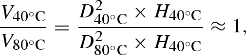 |
3.1 |
Figure 6.

Optical images of (a) the nHA relics deposited at 40°C substrate temperature and (b) the relics deposited at 80°C substrate temperature.
where V is the mean volume of the nHA relics, D the mean diameter of the relics and H the mean height of the nHA relics. Therefore, the ratio of the mean heights of nHA relics deposited at 40°C and 80°C is approximately 1:3, and the mean height of a single nHA relic formed at 80°C is nearly three times the height of the nHA relic deposited at a lower temperature.
Owing to this evolution of the nHA relics during spraying with the heated substrate, the topography of the nHA lines has also been significantly influenced by the substrate temperature. As shown in figure 7a,b, the tandem scanning microscopic images show that the base layer and the peak layer of the nHA lines prepared at 40°C substrate temperature. The base layer, shown as a dark region, is approximately 32 µm in width, which matches the measurement on SEM images, and the peak layer of the nHA line, shown as a bright region, is approximately 18 µm in width. The distance between the top and bottom layers, which shows the height of the nHA lines, is 6 µm, with a standard deviation of 1 µm. Figure 7c,d shows the base layer and the peak layer of the nHA lines prepared at 80°C substrate temperature. The bottom layer is approximately 15 µm in width, and the top layer of the lines is approximately 4 µm in width only. The height of the nHA lines is 16 µm, with a standard deviation of 2 µm. Therefore, the nHA lines prepared at 80°C substrate temperature present as sharp ridges on the Ti surface, compared with the nHA patterns prepared at 40°C substrate temperature.
Figure 7.

Tandem scanning micrographs of (a) base layer and (b) peak layer of the nHA patterns deposited at 40°C substrate temperature; (c) base layer and (d) peak layer of the nHA patterns deposited at 80°C substrate temperature.
3.4. In vitro study
The cellular morphology can be used as an indication of cell health and orientation. The scanning electron micrographs in figures 8 and 9 demonstrate the cell attachment and numerous cell filopodia anchored to the nHA particles. However, different scenarios of cell morphology were observed on the HA patterns of different dimensions as discussed below.
Figure 8.

Scanning electron micrograph of HOB cells attached on the nHA pattern prepared when the substrate temperature is 40°C.
Figure 9.

Scanning electron micrograph of HOB cells attached on the nHA pattern prepared when the substrate temperature is 80°C.
In the case of broader nHA lines of a higher width, the HOB cells attach and align along the nHA lines as bioactive HA particles provide the preferable sites for cellular attachment (figure 8). However, the cells on the nHA lines with narrower width and larger height present an entirely different morphology. Instead of growing along the HA lines, the cells seem to attach and grow in the spacing between the lines (figure 9). The separated appearance in the cell layer presented in figure 9 is due to the drying process during the SEM sample preparation.
Different behaviours of the cells with respect to the variations in the deposited TAEA patterns are due to the surface topographical effect, which has been exhaustively reviewed by Curtis & Wilkinson (1997), and it is widely accepted that cells are able to switch alignment from ridges to grooves depending on the substrate surface topography and its dimensions. Therefore, differences in HOB cell alignment presented on two different patterns as shown in the scanning electron micrographs of the current work are due to pillar dimensions. The HOB cell is approximately 40 µm. When the HA line matches the HOB cell dimension, the cells sit, attach and grow along their ‘favourite’ HA sites. However, if the HA lines are fine and have sharp ridges, instead of growing along the lines, they attach and grow between the ridges with filopodia anchoring to the nHA sites on the sides.
These observations were further proved by fluorescent confocal microscopy. The images showing differentially stained nuclei and cytoskeletal structures of HOB cells cultured on two nHA-patterned surfaces prepared using TAEA spraying are shown in figure 10. In figure 10a, preferential cell adhesion to the HA is evident, with cells aligning along the HA lines generated (40°C substrate). In contrast, in figure 10b, although the HOB cells are aligned in the same direction, the cytoskeletons of the cells align to bridge the two sides between sharp HA ridges (80°C substrate). Both observations follow the SEM findings.
Figure 10.

Confocal micrographs of actin cytoskeleton for HOB cells on nHA patterns sprayed at (a) 40°C substrate temperature and (b) 80°C substrate temperature. Solid and dashed lines indicate the orientations of the osteoblast cells.
4. Conclusions
An in-depth study of the novel TAEA process has resulted in improving the resolution of the patterns generated. Mainly by increasing the substrate temperature to 80°C, lines of approximately 15 µm width have been prepared. In addition, these lines are higher and sharper than lines deposited at a lower temperature. The in vitro study demonstrated that the HOB cell behaviour and orientation on these patterns have been controlled and modulated by this patterning technology. Thus TAEA spraying is a promising technique in engineering bioactive surfaces and for generating future implant materials for guided bone tissue regeneration.
Acknowledgements
The authors would like to thank the Furlong Research Charitable Foundation for the financial support to initiate this study. UCL is thanked for part funding the PhD research of X.L.
References
- Ahmad Z., Huang J., Edirisinghe M. J., Jayasinghe S. N., Best S. M., Bonfield W., Brooks R. A., Rushton N. 2006. Electrohydrodynamic print-patterning of nano-hydroxyapatite. J. Biomed. Nanotechnol. 2, 201–207. ( 10.1166/jbn.2006.032) [DOI] [Google Scholar]
- Barbucci R., Magnani A., Lamponi S., Pasqui D., Bryan S. 2003. The use of hyaluronan and its sulphated derivative patterned with micrometric scale on glass substrate in melanocyte cell behaviour. Biomaterials 24, 915–926. ( 10.1016/S0142-9612(02)00425-8) [DOI] [PubMed] [Google Scholar]
- Britland S., Morgan H., Stodart B. W., Riehle M., Curtis A., Wilkinson C. 1996. Synergistic and hierarchical adhesive and topographic guidance of BHK cells. Exp. Cell. Res. 228, 313–325. ( 10.1006/excr.1996.0331) [DOI] [PubMed] [Google Scholar]
- Brunette D. M., Chehroudi B. 1999. The effects of the surface topography of micromachined titanium substrata on cell behaviour in vitro and in vivo. J. Biomech. Eng. 121, 49–57. ( 10.1115/1.2798042) [DOI] [PubMed] [Google Scholar]
- Clark P., Connolly P., Curtis A. S. G., Dow J. A. T., Wilkinson C. D. W. 1987. Topographical control of cell behaviour. 1. Simple step cues. Development 99, 439–448. [DOI] [PubMed] [Google Scholar]
- Constantz B. R., et al. 1995. Skeletal repair by in situ formation of the mineral phase of bone. Science 267, 1796–1799. ( 10.1126/science.7892603) [DOI] [PubMed] [Google Scholar]
- Curtis A., Wilkinson C. 1997. Topographical control of cells. Biomaterials 18, 1573–1583. ( 10.1016/S0142-9612(97)00144-0) [DOI] [PubMed] [Google Scholar]
- Di Silvio L., Gurav N. 2001. Osteoblasts. Human cell culture: primary mesenchymal cells, vol. ix, p. 241 London, UK: Kluwer Academic Publishers. [Google Scholar]
- Grace J. M., Marijnissen J. C. M. 1994. A review of liquid atomization by electrical means. J. Aerosol Sci. 25, 1005–1019. ( 10.1016/0021-8502(94)90198-8) [DOI] [Google Scholar]
- Hench L. L. 1998. Bioceramics. J. Am. Ceram. Soc. 81, 1705–1728. [Google Scholar]
- Jaworek A., Krupa A. 1999. Classification of the modes of EHD spraying. J. Aerosol Sci. 30, 873–893. ( 10.1016/S0021-8502(98)00787-3) [DOI] [Google Scholar]
- Jayasinghe S. N., Edirisinghe M. J. 2002. Effect of viscosity on the size of relics produced by electrostatic atomization. J. Aerosol Sci. 33, 1379–1388. ( 10.1016/S0021-8502(02)00088-5) [DOI] [Google Scholar]
- Jayasinghe S. N., Edirisinghe M. J. 2004. Electrostatic atomization of a ceramic suspension. J. Eur. Ceram. Soc. 24, 2203–2213. ( 10.1016/j.jeurceramsoc.2003.07.001) [DOI] [Google Scholar]
- Kern P., Veh J., Michler J. 2007. New developments in through-mask electrochemical micromachining of titanium. J. Micromech. Microeng. 17, 1168–1177. ( 10.1088/0960-1317/17/6/010) [DOI] [Google Scholar]
- Le Guehennec L., Soueidan A., Layrolle P., Amouriq Y. 2007. Surface treatments of titanium dental implants for rapid osseointegration. Dent. Mater. 23, 844–854. ( 10.1016/j.dental.2006.06.025) [DOI] [PubMed] [Google Scholar]
- Li X., Ahmand Z., Huang J., Edirisinghe M. J. 2007. Electrohydrodynamic coating of metal with nano-sized hydroxyapatite. J. Biomed. Mater. Eng. 17, 335–346. [PubMed] [Google Scholar]
- Li X., Huang J., Edirisinghe M. J. 2008. Novel patterning of nano-bioceramics: template-assisted electrohydrodynamic atomization spraying. J. R. Soc. Interface 5, 253–257. ( 10.1098/rsif.2007.1162) [DOI] [PMC free article] [PubMed] [Google Scholar]
- Oonishi H. 1991. Orthopedic applications of hydroxyapatite. Biomaterials 12, 171–178. ( 10.1016/0142-9612(91)90196-H) [DOI] [PubMed] [Google Scholar]
- Peruzzi M., Pedarnig J. D., Sturm H., Huber N., Bauerle D. 2004. F2-laser ablation and micro-patterning of GaPO4. Europhys. Lett. 65, 652–657. ( 10.1209/epl/i2003-10159-2) [DOI] [Google Scholar]
- Puckett S., Pareta R., Webster T. J. 2008. Nano rough micron patterned titanium for directing osteoblast morphology and adhesion. Int. J. Nanomed. 3, 229–241. [DOI] [PMC free article] [PubMed] [Google Scholar]
- Roda A., Guardigli M., Russo C., Pasini P., Baraldini M. 2000. Protein microdeposition using a conventional ink-jet printer. Biotechniques 28, 492–496. [DOI] [PubMed] [Google Scholar]
- Tan J., Saltzman W. M. 2004. Biomaterials with hierarchically defined micro- and nanoscale structure. Biomaterials 25, 3593–3601. ( 10.1016/j.biomaterials.2003.10.034) [DOI] [PubMed] [Google Scholar]
- Webster T. J., Ergun C., Doremus R. H., Siegel R. W., Bizios R. 2000. Enhanced functions of osteoblasts on nanophase ceramics. Biomaterials 21, 1803–1810. ( 10.1016/S0142-9612(00)00075-2) [DOI] [PubMed] [Google Scholar]
- Wilkinson C. D. W., Riehle M., Wood M., Gallagher J., Curtis A. S. G. 2002. The use of materials patterned on a nano- and micrometric scale in cellular engineering. Mater. Sci. Eng. C 19, 263–269. ( 10.1016/S0928-4931(01)00396-4) [DOI] [Google Scholar]