Abstract
In this paper we develop the Point Collocation-based Method of Finite Spheres (PCMFS) to simulate the viscoelastic response of soft biological tissues and evaluate the effectiveness of model order reduction methods such as modal truncation, Hankel optimal model and truncated balanced realization techniques for PCMFS. The PCMFS was developed in [1] as a physics-based technique for real time simulation of surgical procedures. It is a meshfree numerical method in which discretization is performed using a set of nodal points with approximation functions compactly supported on spherical subdomains centered at the nodes. The point collocation method is used as the weighted residual technique where the governing differential equations are directly applied at the nodal points. Since computational speed has a significant role in simulation of surgical procedures, model order reduction methods have been compared for relative gains in efficiency and computational accuracy. Of these methods, truncated balanced realization results in the highest accuracy while modal truncation results in the highest efficiency.
1. Introduction
The goal of surgical simulation is to generate an immersive virtual environment where a human user can interact with virtual three-dimensional organ models in real time using his/her sense of vision as well as touch through specialized haptic interface devices [2]. We are interested in a special class of surgical procedures known as minimally invasive surgery (MIS) [3] where long slender instruments are inserted into the body of the patient through small incisions to perform the operation. Computational speed is a major driving factor in such simulations [2]. While the demand for accuracy is not as high as in simulation based engineering, it is dictated by the just noticeable difference (JND) of the human sensory system [4]. Hence novel computational algorithms are necessary which can deliver the high computational speeds at reasonable accuracy.
In [1] the point collocation-based method of finite spheres (PCMFS) was presented for real time surgery simulation. It is a meshfree numerical method (for a review of meshfree methods, see [5]) in which discretization is performed using a set of nodal points with approximation functions compactly supported on spherical subdomains centered at the nodes. The point collocation method is used as the weighted residual technique where the governing differential equations are directly applied at the nodal points. Structural reanalysis techniques have been developed in [1] to generate computational algorithms that scale linearly with the number of degrees of freedom of the system. However, all applications were limited to linear elastic tissue models.
Soft tissue behavior is complex, exhibiting both nonlinear and viscoelastic response. In [4] we extended the PCMFS method using a multiresolution computational scheme to simulate nonlinear response involving large deformations. However, a St. Venant-Kirchhoff type tissue model was used.
In this paper we apply the PCMFS technique, for the first time, to the solution of viscoelastic soft tissue response. The advantage of this method over traditional finite element methods is the elimination of expensive numerical integration and the flexibility offered by the shape functions which may intersect and overlap, unlike finite elements which are constrained to abut each other. Hence, there is no problem with the Jacobian becoming zero or negative. In addition, the PCMFS shape functions have higher order continuity than finite element shape functions and hence, unlike finite element shape functions, may be used with the strong formulation.
In previous literature, an adaptive method for modeling dynamic viscoelastic deformation in real time using an explicit finite element method was developed in [6]. In [7] a viscoelastic finite element formulation for the simulation of viscoelastic deformable objects was developed using a Maxwell solid model with a single memory parameter. A constant mechanical properties for the material was assumed at the beginning and then the parameters of the Prony series corresponding to the Maxwell model were obtained by matching their compliance functions while minimizing the relative error. A lumped mass matrix and nested tetrahedral meshes were used to reduce the number of real-time computations.
In [8] a real time finite element model for the simulation of linear viscoelastic tissue behavior was proposed, and a method for measuring and integrating experimental data for the viscoelastic material properties of soft tissues into the model for realistic display of visual deformations and interaction forces was presented. A precomputation step and an algorithm for updating the viscoelastic response was used to reduce the computational cost.
In [9] a method for simulating viscoelastic solids in real time was introduced based on a parameter estimation method derived from physical measurements of real objects. To model the viscoelastic effects, a discrete Green’s function matrix (DGFM) was combined with particle systems by replacing the spring-like relations in the DGFM with compositions of springs and dashpots. This allowed the simulation of the viscoelastic behavior while retaining the DGFM for the primary deformation calculations. This method achieved real time update rates for visual display of deformations. However, it used a quasi-static elastic model for calculating and reflecting interaction forces through a haptic interface device.
In [10] a tensor-mass method for the finite-element simulation of nonlinear viscoelastic mechanical deformations of biological soft tissues was developed. The material nonlinearity was introduced by local modification of the stiffness tensors while keeping the strain tensor linear and adjusting the Lame constants. The Kelvin-Voigt viscoelastic model was used. The parameters were adjusted using an experimental setup designed to characterize the material properties of biological tissues through in vitro experiments.
Most of these methods are highly simplified and suffer from major drawbacks including nonphysical tissue models, simplistic geometrical shapes, and in most cases, lack of realistic force feedback since real time force feedback is much more demanding than real time graphical display [2].
The PCMFS reduces the computational burden significantly by obviating the need for expensive numerical integration. Model order reduction (MOR) methods have been applied to PCMFS in this paper to increase computational efficiency. Model order reduction methods have been developed for large scale dynamical systems [11, 12, 13] where they are used to approximate the input-output behavior of the system over a certain range of operation using significantly smaller matrices. Exploiting a special initial/boundary value problem for surgical simulation (section 2) we show that the input-output response corresponds to application of prescribed displacements and computing the force at the surgical tool tip, respectively. Model order reduction methods offer an excellent route to computing this input-output response eliminating a large number of degrees of freedom which do not have a significant influence on the output.
There are two major approaches for generating reduced order models for linear time invariant systems; moment matching [14,15,16] and truncated balanced realization [17,18,19]. In moment matching techniques, the system is approximated by a smaller model by curve fitting the full model response. In truncated balanced realization method, on the other hand, the input-output relation to the system response is considered to produce the reduced model. Truncated balanced realization produces a reduced model with good global accuracy and a known frequency domain L∞ error bound [20]. However, it is computationally expensive. On the other hand, moment matching techniques produce higher order models but are less expensive [20].
To the best of our knowledge, model order reduction methods have not been applied with collocation-based meshfree methods in the past. In this paper we will use the PCMFS method to simulate a linear viscoelastic material response and compare several MOR techniques, such as Hankel optimal method, modal truncation, and truncated balanced realization with the goal of finding the method that results in best computational speed with reasonable accuracy.
In section 2 a brief introduction to the PCMFS is provided and the initial/boundary value problem corresponding to surgery simulation is presented. In section 3 the model order reduction methods are presented in the context of the PCMFS. Finally, in section 4 several numerical examples in two- and three-dimensional analysis are considered.
2. The Point-Associated Finite Field (PCMFS) Approach for Viscoelastic Surgery Simulation
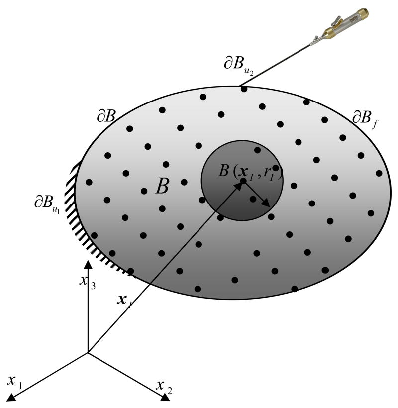
In the PCMFS technique [1] computational particles are sprinkled on the computational domain (Figure 1). At every node ’I’ located at xI an approximation function is defined which is compactly supported on the sphere B I = B (xI, rI) of radius rI centered at the node. The elastodynamic initial/boundary value problem (section 2.1) is solved using point collocation (section 2.2). The moving least squares approximation functions, discussed in section 2.3, are used for discretization and the discretized set of equations are presented in section 2.4.
Figure 1.
Schematic of the PCMFS for dynamic surgery simulation. Discretization of a domain B ⊂ ℛ3 by the PCMFS using a set of nodal points. BI is the open sphere at node I. Natural boundary conditions are defined on ∂B f and the essential boundary conditions are defined on ∂B u; ∂B = ∂B u ∪ ∂B f and ∂B u ∩ ∂B f = 0. Note that ∂Bu = ∂ Bu1 ∪ ∂Bu2 where u(x) = 0 for x ∈ ∂Bu1 and u =utooltip on ∂Bu2 × (0,T)
2.1. The Elastodynamic Initial/Boundary Value Problem
During surgical simulation the surgical tool interacts with the portion ∂Bu2of the body B with boundary ∂B. Homogeneous Dirichlet boundary conditions are prescribed on the portion ∂Bu1 of the boundary and tractions are prescribed on ∂Bf (Figure 1). We are interested in solving the specialized strong form of the following initial/boundary value problem:
| (1) |
| (2) |
| (3) |
| (4) |
| (5) |
| (6) |
where is the stress vector, is the displacement vector and ü denotes second derivative with respect to time. and are the initial displacements and velocities, respectively. The surgical tool interacts with the portion ∂Bu2 of the boundary and prescribes a displacement field u tooltip which is a function of space and time. The displacement on the rest of the Dirichlet boundary (∂Bu2) is assumed to be zero for the entire simulation period (T). is the body force and is the applied traction force. ∂ε is a linear gradient operator and N is a matrix of direction cosine components (nx, ny, nz) of the unit outward normal to the domain boundary which, for three-dimensional analysis, have the following representation:
In the theory of linear viscoelasticity [23,24] the stress can be divided into an elastic part and a viscoelastic contribution as
| (7) |
where
| (8) |
| (9) |
| (10) |
E∞ and E j are the elastic and viscoelastic Young’s moduli, respectively, ν is the Poisson’s ratio and τj is the relaxation time constant with j =1…M.
2.2. Point Collocation
In the point collocation method [21,22] the displacement solution u is approximated by uh and the governing partial differential equations are applied at the nodal points. The discrete set of equations is
| (11) |
| (12) |
| (13) |
| (14) |
| (15) |
| (16) |
The use of smooth weight functions in Eq. (21) allows the higher order derivatives in Eq. (11) to be taken. The point collocation method obviates expensive numerical integration, but results in a nonsymmetric stiffness matrix.
2.3. The Moving Least Squares Approximation Scheme
In PCMFS, the moving least squares [22] technique is used to generate the approximation functions. In this technique, the approximation uh (x,t) of a variable u, using ‘N’ particles, is
| (17) |
where α J = [uJ, vJ, wJ] is the vector of nodal unknowns corresponding to the x, y, and z directions at node ‘J’ and U = [α1 α2 …αN]T. The nodal shape function matrix is
| (18) |
where the shape functions at node ‘J’ are generated using a moving least squares procedure and has the form
| (19) |
with
| (20) |
where P(x) is a vector of monomials, e.g., P(x) =[1, x, y, z] ensures first order accuracy in 3D. We define a positive radial weight function , s ≥ 1 with sJ =||x − xJ||0/rJ at each node ‘J’ which is compactly supported on the sphere at node ‘J’. In our work we have used a quartic spline weight function of the form
| (21) |
2.4. The Discretized Equations
Using the PCMFS approximation (equation 17) the discretization of the strains and stresses are
| (22) |
Let us define a time discretization of the form [0,T] = ∪ n ∈ℕ[tn, t n +1], t n +1 = t n +Δt; Δt is the time step and ℕ is an integer. It is straightforward to show [23] that the internal variables in equation 9 satisfy the following relation
| (23) |
Assuming to be constant through the time interval [tn, tn +1], [24] equation 23 can be written as
| (24) |
where the superscripts n and n+1 indicate the variable value at time tn and tn +1, respectively.
Using equation (22) this may be rewritten as
| (25) |
where .
At time t n+ 1 the first term in the LHS of equation 11 can be expressed using equation 7 as
| (26) |
Hence, using equations 22 and 25
| (27) |
which, in matrix form, is
| (28) |
where
| (29) |
Hence, the discretization of equation 11, using equations 17 and 28 is
| (30) |
with M = [ρH(x)]x =xI.
For nodes on the boundary the discretized forms of equations 12 and 13 are used, i.e. for the nodes with prescribed traction, equation 12, the following discretized form is applied
| (31) |
For nodes on the homogeneous Dirichlet boundary
| (32) |
and nodes with prescribed tooltip displacement
| (33) |
In state space form, the discretized equation can be written as
| (34) |
The output vector is given as
| (35) |
where , and . u(t) is the input which, for our purpose, is unity. The matrix C relates the internal states and the output. Since we are interested in the reaction force at the tooltip, , where . The matrix D reflects the direct influence of the input force to the output, which is zero for our case since the reaction force is computed from the internal stresses and is not directly connected to any of the inputs.
3. Some Model Order Reduction Methods
In this section we will consider three linear model order reduction techniques: Hankel optimal model, modal truncation and truncated balanced realization, in the context of the PCMFS applied to the tissue viscoelasticty problem.
There are different methods for how the reduced order system can be produced, one of the simplest ways is projection methods. The idea in model order reduction using projection is to find a low-dimensional subspace T in which the state vector X can be projected, i.e.
| (36) |
where T is a N ×M projection matrix with M ≪ N, X is a N ×1 original state vector, Z is a M ×1 reduced state vector, and ω is a N ×1vector which can be neglected.
3.1 Hankel optimal model
Hankel optimal model reduction tries to find a reduced system Gr(s) of the original system G(s) by minimizing the following Hankel norm [18]
| (37) |
where G(s) and Gr(s) are the Laplace transforms of the original and reduced system, respectively, i.e.,
| (38) |
To define the Hankel norm we start by defining the observability and controllability gramians [25] of a system such as the one in equation (30). The controllability gramian measures the connectivity between the input and the internal states, X(t), while the observability gramian measures the coupling between the outputs and the internal states.
The controllability and observability gramians, Wr and Wo respectively, are obtained by solving the following Lyapunov equations
| (39) |
where A,B, and C are defined in equations (30) and (31). The Hankel singular values are defined as
| (40) |
where λi are the eigenvalues of A. The Hankel norm of the state space model is then defined as
| (41) |
The Hankel optimal model reduction is one of the best reduction models available [27]. However, it has a cubic rate of growth of complexity which makes it impractical for large systems.
3.2 Truncated balanced realization
In truncated balanced realization we consider a transformed basis Z =TX, where T is a projection matrix. The resulting state space representation
| (42) |
where  =TAT−1, B̂ = TB, Ĉ = CT −1. The resulting gramians are given by [17]
| (43) |
The idea behind truncated balanced realization is to find the projection matrix T that makes the observability and controllability gramians for a system equal to each other and to the Hankel singular value matrix. Then the state space representation can be written as
| (44) |
where Σ is a diagonal matrix with the Hankel singular values, , and .
The reduced model of order k is given by
| (45) |
The idea behind this method is to equalize the coupling of energy from input to states and from states to outputs using the linear transformation T to make the observability and controllability gramians equal and ignore the states that have small coupling.
Truncated balanced realization produces a stable reduced model and has a frequency error bounded in the L∞-norm. However, the algorithm is expensive and it is not widely used for large systems.
3.3 Modal truncation
In modal truncation the system transfer function is decomposed into a summation of simple systems that consist only of single real poles or a complex pair of poles. The reduced model is obtained by retaining the dominant modes. The usual approach of modal truncation is to write A is the Jordan form by similarity transformation
| (46) |
where and retain the low frequency eigen values. While this approach is the simplest it is not obvious which modes might have the most influence on the system unless a detailed analysis of the system is performed.
4. Numerical Examples
In this section we present several numerical examples illustrating the application of the various model order reduction methods in section 3 to the elastodynamic problem in section 2. In section 4.1 we consider the deflection of isotropic elastic membranes and in section 4.2 we present the example of a domain in 3D.
4.1. Elastic Membranes
Here we will consider a circular membrane (4.1.1) and a square membrane (4.1.2) as examples.
4.1.1. Elastic Circular Membrane
First we will consider an isotropic elastic circular membrane of unit radius, fixed at its boundary. The governing partial differential equation for the membrane deflection u(x,y,t) with the boundary and initial conditions are
| (47) |
with
| (48) |
| (49) |
| (50) |
| (51) |
All material properties were assumed to be unity.
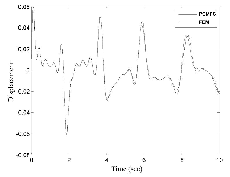
Figure 2 shows the displacement solution of the center of the membrane computed using PCMFS and compared with a finite element solution (ABAQUS®) using 146 linear triangular finite elements. The PCMFS solution was obtained using 500 nodes distributed uniformly in the angular and radial directions.
Figure 2.
Displacement solution at the midpoint of a circular elastic membrane computed using PCMFS and FEM.
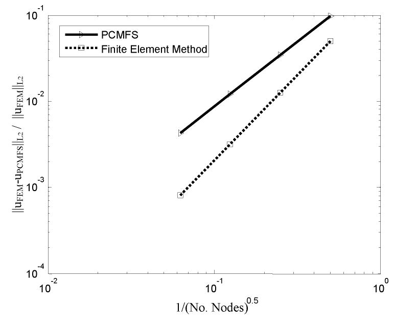
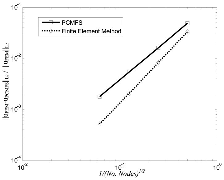
Figure 3 shows the convergence of the solution in the L2 error norm of the displacement field defined as
Figure 3.
The convergence in the L2 error norm for the displacement solution of a circular membrane with PCMFS and FEM.
when the PCMFS and the finite element methods are used. The PCMFS method is clearly less accurate than the finite element method for the same number of nodal points.
However, since no numerical integration is used, the technique is much faster. As explained in the introduction, this slightly lower accuracy is permissible for simulation based surgical training scenarios in view of the enhanced speed.
Figure 4 shows the frequency response for the full system compared with the reduced systems obtained using Hankel optimal model, modal truncation, and truncated balanced realization, respectively. Only 600 states were used in the model order reduction techniques compared to 800 states in the full PCMFS model.
Figure 4.
Comparison of the frequency response of the full PCMFS discretization of the membrane structure with (a) Hankel optimal model (HOM), (b) modal truncation (MT), and (c) truncated balanced realization (TBR) MOR techniques.
From the figure it may be observed that the truncated balanced realization performs the best in capturing most of the dynamics of the full system. Hankel optimal model has a steady state error in the higher frequencies. Of the three methods, modal truncation has the highest error and it is not able to capture the peaks in the frequency domain since the modes corresponding to these frequencies have been ignored through the reduction.
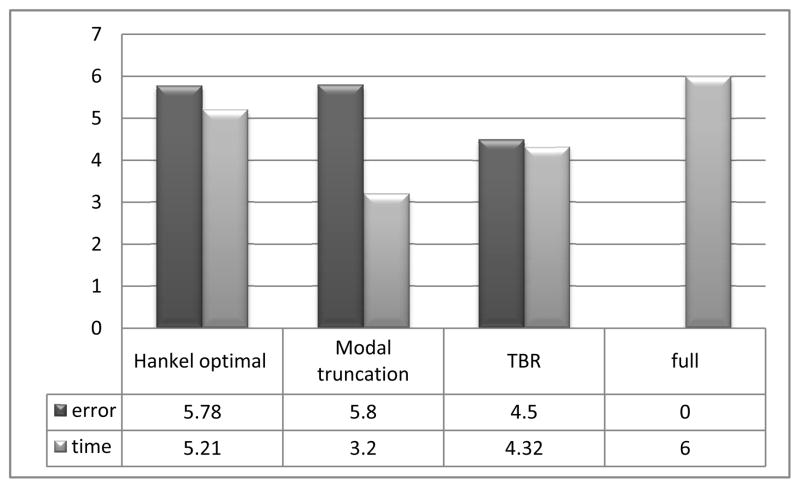
Figure 5 shows the time in seconds used to solve the problem and relative error for each of the model order reduction techniques. The relative error is defined as
Figure 5.
Relative error and computational time for each of the model order reduction techniques are indicated by the lengths of the bars.
It is observed that truncated balanced realization results in the lowest relative error compared to the full model while modal truncation results in highest computational speed.
4.1.2. Elastic Square Membrane
In the next example we consider a square membrane with sides of unit length fixed along the sides.
The boundary conditions are
| (52) |
| (53) |
| (54) |
| (55) |
The viscoelastic model in section 2 was used with M=1, E∞ = 1.0, ρ = 1.0, and E1 = η1 = 1.0.
Figure 6 shows the convergence in the L2 error norm of the displacement solved using PCMFS and FEM. ABAQUS® was used for the FEM simulation with linear triangular elements.
Figure 6.
The convergence in the L2 error norm of the solution obtained using PCMFS and FEM.
Now we will look at the solution using different model order reduction techniques. The membrane is discretized using 200 PCMFS nodes, distributed uniformly, resulting in 400 degrees of freedom (i.e., the number of states is 400). The model order reduction methods use 200 degrees of freedom.
Figure 7 shows the frequency response of the full system compared with and the reduced order systems
Figure 7.
Comparison of the frequency response of the full PCMFS discretization of the membrane structure with (a) Hankel optimal model, (b) modal truncation, and (c) truncated balanced realization MOR techniques..
It can be seen that the Hankel optimal model does not perform well in the higher frequency regime while modal truncation does not perform well at lower frequencies. Truncated balanced realization captures most of the dynamics of the system. However, it has a steady error at high frequencies.
Figure 8 shows the time in seconds and error for each of the model order reduction techniques. As in the previous example, truncated balanced realization results in lowest error while modal truncation method results in the highest computational efficiency.
Figure 8.
Relative error and computational time for each of the MOR techniques are indicated by the lengths of the bars.
4.2. Elastic cube in R3
Our final example is a unit cube composed of a linear isotropic viscoelastic material of density ρ = 10Kg/m3 and viscoelastic parameters γ1 = 1 and τ1 = 1.0s. The bottom surface of the cube is fixed and a sinusoidal displacement is applied at the center of the top surface. All initial accelerations, velocities and displacements are set to zero. The viscoelastic dynamic response was calculated using a time step Δt = 0.001s for a total of T=5 seconds. The Newmark time integration algorithm was used to approximate the accelerations and velocities.
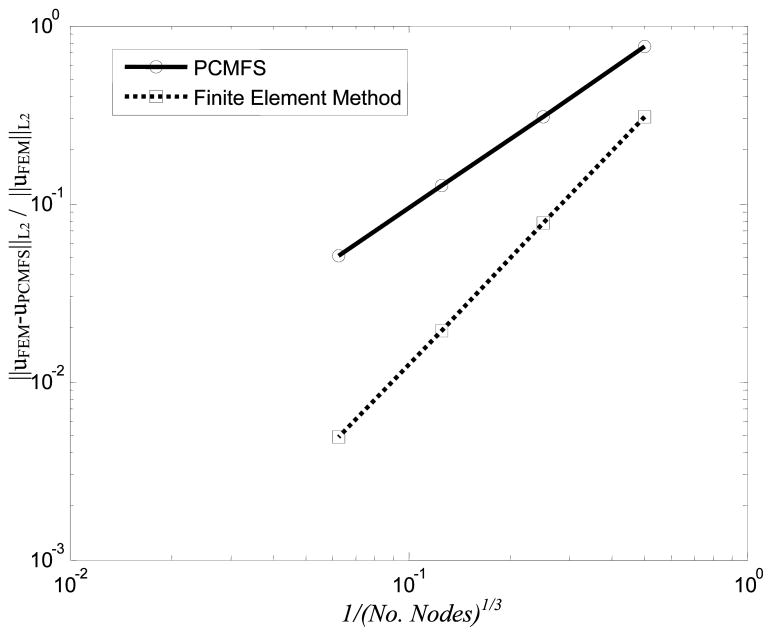
In Figure 9 we plot the convergence of the solution in the L2 norm using PCMFS and FEM. Linear tetrahedral elements were used in FEM solved using ABAQUS® and PCMFS with linear consistency was used.
Figure 9.
The convergence in the L2 error norm of the displacement solution obtained using FEM and PCMFS.
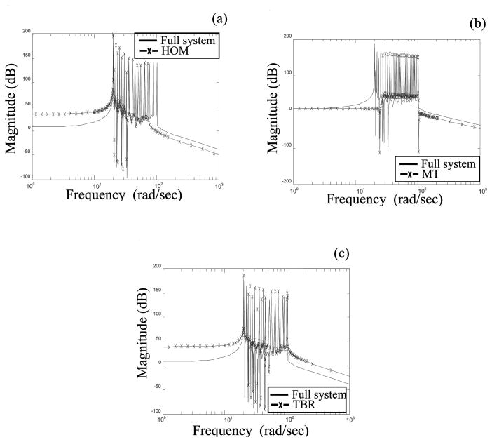
The different model order reduction methods are compared for a full system model discretized using 1000 nodes (i.e., 3000 degrees of freedom). Figure 10(a) shows the frequency plots, compared with the full system, when the Hankel optimal model reduction method is used to solve the problem. In Figure 10(b) and (c) we show the frequency response for the full model and the reduced order models when the modal truncation and truncated balanced realization methods are used, respectively.
Figure 10.
Frequency response of the unit cube with the full system and (a) Hankel optimal model (b) Modal truncation (c) Truncated balanced realization MOR technique.
The Hankel optimal norm method as well as the modal truncation method performs poorly in the high frequency regimes as information is lost in the truncated modes. A trial and error method may be used to find the most important modes for the operating frequencies which would increase accuracy. Using truncated balanced realization we were able to find the best reduced order model for the system that captures most of the dynamics even in the high frequency region.
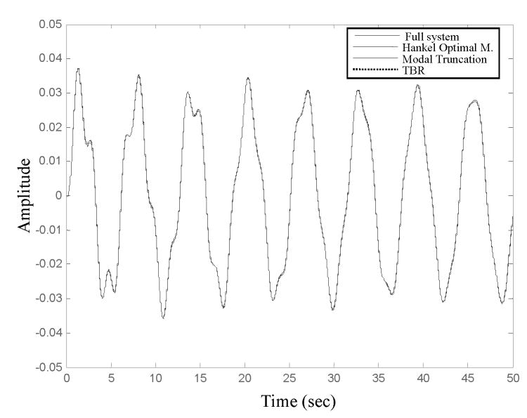
Figure 11 shows the time domain solution of the reaction force at the midpoint of the upper surface solved using the full PCMFS model and the reduced models obtained using the three model order reduction methods.
Figure 11.
Time domain solution of the reaction force for the midpoint of the upper surface of the cube for the full system as well as different model order reduced system using the PCMFS approximation scheme.
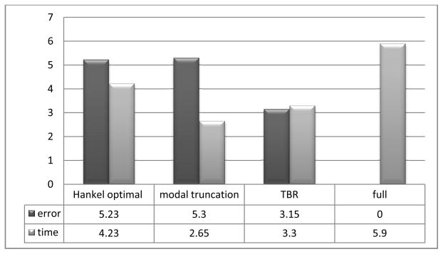
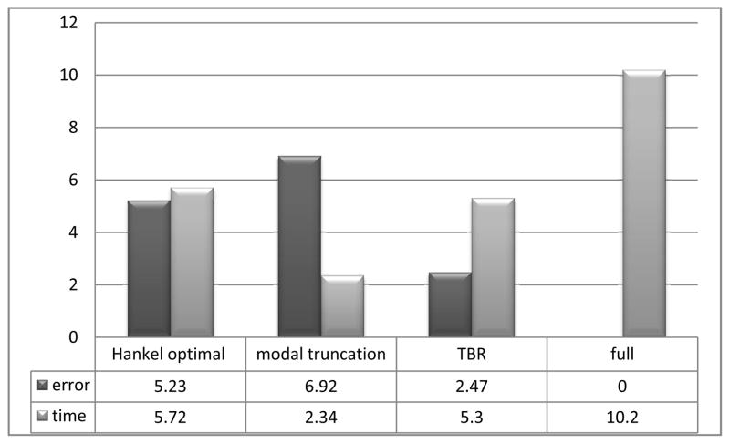
In Figure 12 we compare the relative error and solution times. The best accuracy was obtained using the truncated balanced realization method while modal truncation gave the lowest time required for the simulation.
Figure 12.
Relative error and solution time for each of the MOR techniques is indicated by the length of the bar.
5. Concluding Remarks
In this paper we have developed a point collocation-based method of finite spheres approach for the solution of linear viscoelasticity problems that arise in the simulation of soft tissue response. In this technique an approximation is generated using the moving least squares method while the point collocation method is used as the weighted residual technique. The advantage of this method is that numerical integration is not necessary which allows efficient computations necessary for the simulation of applications such as virtual surgery.
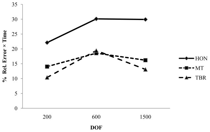
Model order reduction methods, used extensively in the field of large scale dynamical systems, have been applied to reduce computational costs. Three such techniques including Hankel optimal norm method, modal truncation method and truncated balanced realization method have been compared for their relative efficiency and computational costs. In Figure 13 we plot the product of percent relative error and computational time for the three example problems presented in section 4. A low value of this product indicates a method that performs the fastest with minimum error. Of the three methods tested, truncated balanced realization emerges as the technique that results in the lowest value of this product while Hankel optimal norm method results in the highest value. While truncated balanced realization gave the highest accuracy, modal truncation method gave the least time requirement. Hankel optimal model and truncated balanced realization reduction methods are more mathematically involved, their computational cost is relatively high compared to modal truncation. However, in modal truncation it is not easy to decide which modes have the greatest influence on the output. In truncated balanced realization the input output relation to the internal states is realized and all the states that are highly connected to the output are retained, which makes it more stable and accurate. Hankel optimal model uses the past input to predict the future output and for a highly oscillating input the output will have a steady error as we have seen in the example problems in the previous section.
Figure 13.
Product of % relative error and time for each of the MOR techniques for different number of DOF.
Whether truncated balanced realization is indeed the best method for surgical simulation remains to be seen. We are currently developing large scale simulations involving realistic organ geometries obtained from segmented images of the Visible Human project dataset. The degrees of freedom associated with these simulations are orders of magnitude higher than the problems considered here.
References
- 1.De S, Lim Y, Manivannan M, Srinivasan MA. Physically realistic virtual surgery using the point-associated finite field (PCMFS) approach. Presence: Teleoper Virtual Environ. 2006;15(3):294–308. [Google Scholar]
- 2.Basdogan C, De S, Kim J, Manivannan M, Srinivasan MA. The role of haptics in medical simulations. IEEE Computer Graphics and Applications. 2004;24(2):56–64. doi: 10.1109/mcg.2004.1274062. [DOI] [PubMed] [Google Scholar]
- 3.Mack MJ. Minimally invasive and robotic surgery. Journal of American Medical Association. 2001;192:2355–2375. [Google Scholar]
- 4.Lim YJ, De S. Physically realistic virtual surgery: modeling nonlinear tissue response using a point-associated finite field (PAFF) approach. Computer Methods in Applied Mechanics and Engineering. in press. [Google Scholar]
- 5.De S, Bathe KJ. Towards an efficient meshless computational technique: the method of finite spheres. Engineering Computations. 2001;18:170–192. [Google Scholar]
- 6.Debunne G, Desbrun M, Cani M, Barr AH. Dynamic real-time deformations using space & time adaptive sampling. Proceedings of the 28th Annual Conference on Computer Graphics and interactive Techniques SIGGRAPH ’01; New York, NY: ACM Press; 2001. pp. 31–36. [Google Scholar]
- 7.Hauth M, Groß J, Straßer W. Interactive physically based solid dynamics. Proceedings of the 2003 ACM Siggraph/Eurographics Symposium on Computer Animation; San Diego, California. July 26 – 27, 2003. [Google Scholar]; Symposium on Computer Animation. Eurographics Association; Aire-la-Ville, Switzerland. 17–27, 2003. [Google Scholar]
- 8.Sedef M, Samur E, Basdogan C. Real-Time Finite-Element Simulation of Linear Viscoelastic Tissue Behavior Based on Experimental Data. IEEE Comput Graph Appl. 2006;26(6):58–68. doi: 10.1109/mcg.2006.135. [DOI] [PubMed] [Google Scholar]
- 9.Schoner JL, Lang J, Seidel HP. Measurement-Based Interactive Simulation of Viscoelastic Solids. Computer Graphics Forum. 2004;23(3):547–556. [Google Scholar]
- 10.Schwartz JM, Denninger M, Rancourt D, Moisan C, Laurendeau D. Modeling Liver Tissue Properties Using a Non-linear Visco-Elastic Model for Surgery Simulation. Medical Image Analysis. 2005;9(2):103–1127. doi: 10.1016/j.media.2004.11.002. [DOI] [PubMed] [Google Scholar]
- 11.Antoulas AC. Approximation of Large-Scale Dynamical Systems. Society for Industrial and Applied Mathematic (SIAM) 2005 [Google Scholar]
- 12.Freund RW. Krylov-subspace methods for reduced-order modeling in circuit simulation. J Comput Appl Math. 2000;123(1–2):395–421. [Google Scholar]
- 13.Rudnyi EB, Korvink JG. Review: Automatic Model Reduction for Transient Simulation of MEMS-based Devices. Sensors Update. 2002;11(1):3–33. [Google Scholar]
- 14.Feldmann P, Freund RW. Efficient linear circuit analysis by Padé approximation via the Lanczos process. Proceedings of the Conference on European Design Automation (Grenoble, France). European Design Automation Conference; Los Alamitos, CA: IEEE Computer Society Press; 1994. pp. 170–175. [Google Scholar]
- 15.Freund RW, Feldmann P. Reduced-order modeling of large passive linear circuits by means of the SYPVL algorithm. Proceedings of the 1996 IEEE/ACM international Conference on Computer-Aided Design; San Jose, California, United States. November 10 – 14, 1996. [Google Scholar]; International Conference on Computer Aided Design; Washington, DC: IEEE Computer Society; 1996. pp. 280–287. [Google Scholar]
- 16.Kamon M, Wang F, White J. Generating nearly optimally compact models from krylov-subspace based reduced-order models. IEEE Transactions on Circuits and Systems-II: Analog and Digital Signal Processing. 2000;47(4):239–248. [Google Scholar]
- 17.Moore B. Principal component analysis in linear systems controllability, observability and model reduction. IEEE Transactions on Automatic Control. 1981;26(1) [Google Scholar]
- 18.Penzl T. Numerical solution of generalized Lyapunov equations. Advances in Computational Mathematics. 1998;8(1):33–48. [Google Scholar]
- 19.Tombs MS, Postlethwaite I. Truncated balanced realization of a stable nonminimal state space system. Internat J Control. 1987;46(4):1319–1330. [Google Scholar]
- 20.Li JR. PhD thesis. 2000. Model Reduction of Large Linear Systems via Low Rank System Gramians. [Google Scholar]
- 21.Bathe KJ. Finite Element Procedures. Prentice-Hall; Englewood Cliffs, USA: 1996. [Google Scholar]
- 22.Zienkiewicz OC, Taylor RL. The Finite Element Method Set. 6. Butterworth-Heinemann; 2005. [Google Scholar]
- 23.Simo JC, Hughes TJR. Computational Inelasticity. Springer; 2004. [Google Scholar]
- 24.Taylor RL, Pister KS, Goudreau GL. Thermomechanical analysis of viscoelastic solids. International Journal for Numerical Methods in Engineering. 1970;2(1):45–59. [Google Scholar]
- 25.Skgestal S, Postlethwaite I. Analysis and Design. John Wiley & Sons; Multivariable feedback Control. [Google Scholar]
- 26.Glover K. All Optimal Hankel Norm Approximation of Linear Multivariable Systems, and Their L-infinity error Bounds. Int J Control. 1984;39(6):1145–1193. [Google Scholar]
- 27.Zhou K, Doyle, Glover K. Robust and optimal control. Prentice Hall; 1995. [Google Scholar]


