Abstract
Cells can secrete biotherapeutic molecules that can replace or restore host function. The transplantation of such cells is a promising therapeutic modality for the treatment of several diseases including type 1 diabetes mellitus. These cellular grafts are encapsulated in semipermeable and immunoisolative membranes to protect them from the host immune system, while allowing the transport of nutrients and small molecules that are required for cell survival and function. The authors report on SU-8-based biocompatible immunoisolative cuboid microcontainers for cell transplantation. Each microcontainer comprises a 300×300×250 or a 1100×1100×250 μm3 SU-8 hollowed cuboid base that houses the cells and an optically transparent SU-8-based nanoporous lid that closes the device. The hollowed cuboid base was formed by conventional optical lithography to have 8 nl (200×200×200 μm3) encapsulation volume for cellular payload. The lid comprises a thick SU-8 slab with an array of cylindrical wells, whose bottom surface is sealed with a thin nanoporous SU-8 membrane. The nanoporous membrane was created from a 100 nm grating (width and spacing) initial silicon mold subjected to a repeated cycle of oxidation and wet etching to achieve a 20 nm wide and 200 nm pitch nano silicon grating. Nanoimprinting and oblique-angle metal deposition, followed by inductively coupled plasma etching were utilized to create 15 nm wide and 350–450 nm deep nanoslots in the thin SU-8 membrane. Isolated mouse islets were encapsulated in the hollowed cuboid base and the nanoporous lid was assembled on top. The penetration of large and small molecules into the microcontainer was observed with fluorescence.
I. Introduction
There are several hormone deficiency diseases such as diabetes, parathyroid disease, and Parkinson's disease.1 Among the approaches to treat such diseases, the most obvious approach is hormone injection2 such as insulin injection for diabetes treatment as often as several shots a day. In order to avoid inconvenient and often painful frequent injections, other approaches, such as pancreas transplantation3 and islet transplantation,4,5 have been studied. However, there is a severe shortage of donor organs6 and there are numerous postoperative complications in organ transplantation. Although the islet transplantation success rate has continually increased, numerous challenges to the long term survival of the graft, such as the consistent usage of immunosuppressive drugs, still remain unresolved.5
Encapsulation provides a mechanism for the protection of transplanted cells from the host immune system, eliminating the requirement of immunosuppressive drugs. Ever since Chang7 proposed to use ultrathin polymer membrane microcapsules for the immunoprotection of transplanted cells, there have been various investigations8,9 to realize immunoisolative cell transplantation devices. The use of microcapsules made of alginate hydrogel (a marine polysaccharide) is one of the most common approaches in cell encapsulation therapy.9 However, alginate-based microcapsules have exhibited a broad distribution of pore sizes, which, in turn, allows undesired immune components to diffuse through the microcapsule and eventually leads to the destruction of encapsulated cells. Alginate-based microcapsules also showed insufficient resistance to organic solvents and inadequate mechanical strength. Microelectromechanical systems (MEMS)-based biocapsules10,11 have provided uniform membrane porosity and mechanical and chemical stability. However, these biocapsules are of the order of several millimeters, and therefore are not small enough to be implanted in many sites.
Self-folded cubic containers have also been studied for generic microassembly application12 and cell encapsulation application.13 In this approach, containers are fabricated on planar substrates to have six planar faces and hinges between faces. Self-folding was realized by electrostatically driven folding of conducting polymer/gold bilayers connecting two rigid plates12 or surface tension of molten Sn/Pb solder,13 which was reported by one of the co-authors of this article. Advantages of this approach include self-folding, which greatly simplifies the assembly process and controllable dimensions as it is based on lithographic processes. The disadvantage of this approach is that the device hinges are, in their current form, primarily made of nonbiocompatible materials and are fabricated using high temperatures and harmful chemicals.
To address the aforesaid challenges associated with cell encapsulation strategies, we present a novel biocompatible microcontainer comprising a hollowed cuboid base for containing the cells and an optically transparent nanoporous lid. A combination of nanoimprint lithography and oblique-angle metal deposition as well as conventional optical lithography were utilized to make a dense array of narrow (down to 15 nm) nanoslots over large areas in SU-8 that may eventually serve as a molecular filter to immunoisolate cells in cell transplantation application. The width of the nanoslots is designed to allow bidirectional transfer of small molecules such as oxygen but prevents the entry of large molecules of the host immune system, facilitating cell survival and function in an immunoisolated environment.
II. Experiment
A. Design criteria
There are several design criteria for the potential use of the microcontainers for cell transplantation applications. First, the microcontainer material/surfaces must be biocompatible as it interacts with both the graft and the host. Second, the microcontainer should encapsulate live cells in a manner where transplanted cells are protected from attack by the host immune system, specifically preventing the diffusion of large molecules such as immunoglobulins and complement proteins. Third, the microcontainer must allow the exchange of nutrients, cellular waste products, secretagogues, and hormones between the graft and the host. Fourth, the microcontainer must be mechanically and chemically stable before and after transplantation.
We selected the most commonly used photosensitive polymer material SU-8 (MicroChem Corp., Newton, MA) for our microcontainer. Voskerician et al.14 reported biocompatibility and biofouling characteristics of various materials used for MEMS drug delivery devices and found that SU-8 is biocompatible and shows reduced biofouling. One of the co-authors of this article reported chronic (51 weeks) recording of fiber spike signals using SU-8-based neural probe implanted in 13 rats without noticeable damage of tissue,15 which further supports the biocompatibility of SU-8-based cell transplantation devices.
In order to encapsulate live cells for transplantation, the microcontainer must have enough space for loading live cell grafts and must completely enclose the cells. The microcontainer must be semipermeable and should allow the free flow of nutrients, cellular waste products, and hormones, while restricting the entry of large molecules from the host immune system that are detrimental to cell survival. It has been reported that membranes with 24.5 nm pores allow diffusion of insulin and glucose.11 In this work, we selected nanoimprint lithography to realize the nanoporous membrane, while conventional optical lithography was chosen to fabricate the SU-8 microcontainer.
B. Device concept
The SU-8-based microcontainer reported here is of cuboid shape and is intended for islet transplantation. The microcontainer is composed of a hollowed cuboid base and a nanoporous lid, as shown in Fig. 1(a). The nanoporous lid can be assembled on top of the hollowed cuboid base after the loading of cells inside the base. The dimensions of the hollowed cuboid base are either 300×300×250 or 1100×1100×250 μm3 with a 200×200×200 μm3 (8 nl) cubic cell encapsulation space. The thickness of the bottom face of the hollowed cuboid base is 50 μm and the width of the four side faces are either 50 μm for the smaller microcontainer or 450 μm for the larger one. The small dimension microcontainer is intended for transplantation and the large dimension microcontainer is intended for easy handling in in vitro tests. The diameter of freshly isolated islets are in the ∼50–300 μm range, and islets of less than 200 μm in diameter show better survival than large islets.16 Both small and large versions of microcontainers provide an encapsulation volume that can accommodate islets with maximum diameter of 200 μm.
Fig. 1.
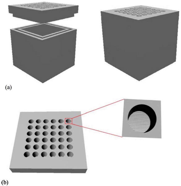
Conceptual diagram of the nanoporous microcontainer: (a) the hollowed cuboid base and the nanoporous lid before (left panel) and after assembly (right panel), and (b) the nanoporous lid as seen from above, with a magnified depiction of a well that exposes the thin nanoporous membrane under it.
The nanoporous lid comprises an array of cylindrical wells (30 μm in diameter) embedded into a 1100×1100×100 or 300×300×30 μm3 SU-8 layer. The bottom surface is sealed by a thin SU-8 membrane (350–450 nm) that has a dense array of 20 nm wide slits that permit molecular transport [Fig. 1(b)]. The thick SU-8 slab imparts mechanical strength to the thin membrane; the thin membrane facilitates the rapid transport of nutrients and important cell signaling molecules. The lid should be strong enough to withstand the pressures and thermal shocks applied during the fabrication process and also render size selective porosity to the device.
C. Fabrication of the hollowed cuboid base
Figure 2 shows the process flow for the fabrication of the hollowed cuboid base. Fabrication was started with spin casting of 50 μm SU-8 2025 photoresist on an oxidized silicon wafer with 2 μm oxide. The SU-8 layer was patterned using conventional optical lithography to form the bottom face of the hollowed cuboid base. Next, a 200 μm thick SU-8 2075 photoresist was spun on the patterned 50 μm thick SU-8 bottom face and a planarization process was performed due to the high viscosity of SU-8. Then, it was baked and patterned using optical lithography to form the four sidewalls of the hollowed cuboid base. Finally, these hollowed cuboid bases were released from oxidized silicon wafer by buffered oxide etchant (BOE).
Fig. 2.

Fabrication process of the hollowed cuboid base: (a) spin coating of 50 μm thick SU-8, (b) patterning of the bottom face, (c) spin coating of 200 μm thick SU-8, and (d) patterning of the four sidewalls.
D. 20 nm wide 200 nm pitch nanograting silicon mold fabrication
In order to make 20 nm or smaller width nanoslots in a large area of SU-8, we fabricated a silicon mold with approximately 20 nm wide grating and 200 nm pitch for nanoimprinting. To fabricate this mold, a layer of SU-8 (∼65 nm) was spin coated on an oxidized Si wafer (∼50 nm SiO2) and imprinted with a silicon master mold to yield a line and space grating over an area of ∼6 cm2. The imprint with the master mold was done at 85 °C and 3 MPa for 15 min [Fig. 3 (step 1)]. Demolding was done at 35 °C, followed by ultraviolet exposure with dose of 450 mJ/cm2 and postexposure bake at 95 °C. The imprinted SU-8 grating was transferred to the SiO2 and then the Si layer by a series of plasma etches in inductively coupled plasma (ICP). First, the exposed SU-8 residue was etched by oxygen plasma, followed by etching in a mixture of C4F8, CHF3, and Ar to transfer the pattern down to the SiO2. Next, the pattern was further transferred into Si by plasma etching in chlorine (300 W ICP power, 100 W bias power, 5 mTorr, and 60 °C chuck temperature), thereby etching Si to a depth of ∼100 nm. The final pattern transferred to Si is a line and space grating with ∼140 nm Si lines separated by ∼60 nm spaces. After the removal of the remaining oxide mask, the resulting Si grating was repeatedly oxidized in a furnace in O2 at 900 °C, with the grown oxide etched by BOE to gradually reduce the grating dimension. Figure 4(a) shows a top view scanning electron microscope (SEM) image of the Si grating after the second oxidation and oxide removal step, while Fig. 4(b) shows the final Si mold (after all oxidation and oxide etching steps) with ∼20 nm wide Si lines.
Fig. 3.
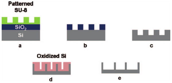
Fabrication process of the Si mold for nanoimprint process: (a) imprinted SU-8, (b) transfer of pattern to SiO2 by fluorine ICP etch, (c) transfer of pattern to Si by chlorine ICP etch; (d) repeated oxidation and oxide removal by BOE, and (e) final Si mold.
Fig. 4.
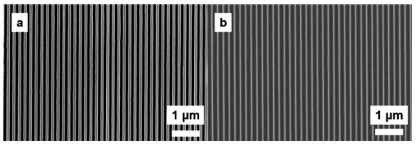
SEM micrographs showing (a) the Si grating after the second oxidation and oxide etch step and (b) the final Si grating (after all oxidation and oxide etch steps) with ∼20 nm wide Si lines that is used to make the nanoslots.
E. Fabrication of the nanoporous lid
The process flow for the fabrication of the nanoporous lid is shown in Fig. 5. A layer of SU-8 (∼450 nm) was spin coated on an oxidized Si wafer (∼2 μm SiO2) and imprinted with the 20 nm wide, 200 nm pitch nanograting mold fabricated as detailed in Sec. II D. The imprinting condition was same as that for the Si mold fabrication in Sec. II D. Cr was selectively evaporated on the imprinted SU-8 gratings at 35 °C, followed by plasma etching in oxygen to etch exposed SU-8 [Fig. 5(d)] and Cr hard mask wet etching. Figure 6 shows a SEM image of the cross section of the imprinted and etched SU-8 membrane, showing 15–20 nm wide openings at the top. During plasma etching, there is a slight widening of the nanoslots beyond the dimension of the top opening in the imprinted SU-8. However, due to the highly directional nature of ICP etching, the transferred dimension at the bottom of the trench is not significantly different from the topmost dimension. Also, as a result of the protection provided by the metal on top of the imprinted SU-8, the top dimension of the nanoslot remains unchanged. The dimension of the nanoslots can be scaled down further by evaporating metal at more oblique angles or by simply evaporating a thicker layer of metal, which, in turn, reduces the gap.
Fig. 5.
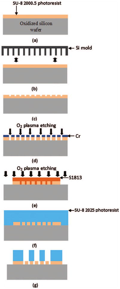
Fabrication process of the nanoporous lid: (a) spin coating of 350 nm SU-8, (b) nanoimprinting with a Si mold, (c) imprinted SU-8 membrane, (d) oxygen plasma etching of SU-8 after oblique-angle metal deposition, (e) S1813 patterning and oxygen plasma etching for the formation of nanoporous lids, (f) spin coating of 30 μm thick SU-8, and (g) patterning of circular trench array.
Fig. 6.
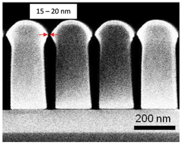
SEM image showing cross section of the nanotrenches in SU-8. The topmost nanoslot opening is as narrow as 15 nm.
After the formation of the nanoslots in the SU-8 membrane, S1813 was spin cast and patterned to form a 300×300 or a 1100×1100 μm2 square [Fig. 5(e)]. O2 plasma etching was performed at 5 mTorr with an ICP rf power of 300 W and a bias rf power of 100 W to remove the 350–450 nm nanoslotted SU-8 membrane except in the square area of 300×300 or 1100×1100 μm2 to create the footprint of the lid. After the nanoslotted SU-8 membrane was patterned, S1813 was removed with acetone. Then, a 30 μm thick SU-8 2025 was spin cast [Fig. 5(f)] and patterned directly on top of the nanoslotted SU-8 membrane so that the nanoslots were placed at the bottom of 30 μm diameter circular trenches [Fig. 5(g)]. After the formation of a 30 μm thick SU-8 trench array on top of the nanoslotted 350–450 nm SU-8 membrane, nanoporous lids were released from the oxidized silicon wafer by BOE. Figure 7 shows SEM images of the overall view of the 300×300×250 μm3 hollowed cuboid base and the 300×300 μm2 nanoporous lid. For the 1100×1100 μm2 nanoporous lid, a 100 μm thick SU-8 was used instead of a 30 μm SU-8 2025.
Fig. 7.

SEM images showing (a) the SU-8 hollowed cuboid base and (b) the nanoporous microcontainer lid (modified with permission from Ref. 18). (c) Encapsulated islet shows uptake of the molecular dye FM 4-64, suggesting adequate device porosity for the transport of nutrients, secretagogues, and hormones necessary for cell survival and function.
F. Loading islets in the hollowed cuboid base
Islets were maintained in modified Roswell Park Memorial Institute (RPMI) medium supplemented with 10% Fetal Bovine Serum (FBS), 1% Penicillin/Streptomycin, and 2% INS-1 solution [4-(2-hydroxyethyl)-1-piperazineethanesulfonic acid (HEPES) sodium salt, 0.5M; l-glutamine, 100 mM; sodium pyruvate, 50 mM; β-mercaptoethanol, 2.5 mM; pH 7.4]. Islets were pipetted into the encapsulation space of the cuboid base and allowed to settle under gravity. The bases were then closed with the nanoporous lids and maintained in a tissue culture dish.
G. Islet staining
The size-dependent selective molecular porosity of the nanoporous microcontainer was verified using the islet-specific fluorescent probes lectin-fluorescein isothiocyanate (FITC) (140 kDa) and FM 4-64 (608 Da). The lectin conjugate was selected because it is slightly smaller than the immunoglobulins and complement proteins of the host immune system, while FM 4-64 molecule was selected because it is larger than the cell signaling molecules such as insulin and glucose. Lectin-FITC staining solution was prepared by adding 120 μl of lectin-FITC [140 kDa; 1 mg/ml in phosphate buffered saline (PBS) (www.sigma.com)] to 720 μl of RPMI medium. FM 4-64 [607 Da (www.sigma.com)] solution was prepared in HBSS at a concentration of 1 μg/ml.
200 μl of lectin-FITC solution was added to the tissue culture dish containing the microcontainers and the dish was incubated at 37 °C, 5% CO2 for 24 h. After 24 h, 2 μl of FM 4-64 solution was added, followed by an additional 30 min incubation. The medium was then removed and the microcontainers were washed thrice with PBS to remove the unbound dye. The microcontainers were then observed with a Leica TCS SP5 laser scanning confocal microscope. Both dyes were excited at 488 nm using the microscope's argon ion laser. The lectin-FITC fluorescence was observed in the green channel (530 nm) and the FM 4-64 was observed in the red channel (630 nm). Images were processed using the IMAGEJ 1.42 software (http://rsbweb.nih.gov/ij).
III. Results and Discussions
Our fabrication scheme resulted in the successful creation of small microcontainers for transplantation applications. Larger microcontainers, with the same encapsulation volume and surface nanoporosity, were similarly created for in vitro testing. The thick walls of the microcontainers ensured that they never ruptured during fabrication and subsequent experiments. The hollowed cuboid housed islets without entrapping them, which is a more physiological approach to grafting as compared with alginate microbeads that entrap and immobilize cells for encapsulation. The use of SU-8 rendered the microcontainers transparent to light and radio frequency waves, which is critical in studying the postencapsulation behavior of cells using optical techniques and magnetic resonance imaging, respectively. Additionally, SU-8 can be easily modified to modulate its porosity17 or functionalized with biosensors that can report on the in vivo microenvironment of the grafts—strategies that we are currently pursuing.
The cyclic oxidation and etching process resulted in an imprint mold with the desired grating width. The mold had the mechanical strength necessary for repeated imprinting. A robust mold for repeated and reproducible imprinting is critical for the high throughput creation of nanoporous membranes in applications such as islet transplantation in diabetics because the process requires the grafting of hundreds of thousands of islets to restore glycemic control in the patient.
Nanoimprinting in SU-8 resulted in the desired nanoslot width at the top of the nanoslot cross section. The nanoslot cross section was narrowed at the bottom after etching, thereby creating additional impedance to the transport of large molecules. The imprinting was carefully performed so that there was no flexing of the SU-8 membrane that could result in nanoslot inhomogeneity across the membrane.
We have previously shown islet survival in SU-8 nanoporous microcontainers to confirm biocompatibility.18 In this study, islets within the microcontainers were incubated in the presence of large and small molecules to ascertain the micro-container's porosity and impedance to molecular transport. Confocal imaging showed the penetration of the small molecule dye FM 4-64 into the microcontainer [Fig. 7(c)]. This result is encouraging because FM 4-64 is larger than insulin and glucose, suggesting the exchange of nutrients, growth factors secretagogues, and hormones necessary for graft survival and function. We also observed some penetration of the large molecule dye, which suggests that some large molecules of the immune system may penetrate into the micro-container since the lectin is slightly larger than the smallest immunoglobulin. However, the mere presence of molecules is not harmful to the graft; a key factor in graft survival is whether complement molecules are active when they arrive at the graft.19 While investigating complements was beyond the scope of this study, we will undertake this in our future work to ascertain whether the nanoporous membrane provides sufficient impedance to large molecules so as to inactivate complements. We will then fine tune the nanoslot width and depth to ensure graft immunoisolation.
IV. Conclusions
Biocompatible SU-8-based nanoporous microcontainers were designed, fabricated, and characterized in preliminary phase for cell encapsulation application. Repeated oxidation and etching was found to be an effective way to create a very small dimension nanoimprint silicon mold. Nanoimprint lithography and oblique-angle metal deposition techniques were utilized to massively reproduce uniform nanoslots in a large area of SU-8. We found that the SU-8-based hollowed cuboid base provides good space for islet encapsulation and anchored the islets strongly in the hollowed cubic space after 24 h. These nanoporous microcontainers have the potential to be used in immunoisolative cell transplantation applications for the treatment of a wide variety of hormone deficiency diseases. The approach can be adapted to encapsulate single cells or bacteria for numerous therapeutic applications.
Acknowledgments
The authors gratefully acknowledge the financial support from the National Institutes of Health (Grant No. NIH R01 EB007456) and an Innovative Award from Juvenile Diabetes Research Foundation (B.G.). They thank Joyce Repa and Philipp Scherer of the Touchstone Diabetes Center at The University of Texas Southwestern Medical Center for kindly providing islets.
Contributor Information
Joonbum Kwon, Department of Electrical Engineering, University of Texas at Dallas, Richardson, Texas 75080.
Krutarth Trivedi, Department of Electrical Engineering, University of Texas at Dallas, Richardson, Texas 75080.
Nemani V. Krishnamurthy, Department of Radiology, University of Texas Southwestern Medical Center at Dallas, Texas 75390
Walter Hu, Department of Electrical Engineering, University of Texas at Dallas, Richardson, Texas 75080.
Jeong-Bong Lee, Department of Electrical Engineering, University of Texas at Dallas, Richardson, Texas 75080.
Barjor Gimi, Department of Electrical Engineering, University of Texas at Dallas, Richardson, Texas 75080 and Department of Radiology, University of Texas Southwestern Medical Center at Dallas, Texas 75390.
References
- 1.Lee M, Bae Y. Adv Drug Delivery Rev. 2000;42:103. doi: 10.1016/s0169-409x(00)00056-9. [DOI] [PubMed] [Google Scholar]
- 2.Pickup J, Mattock M, Kerry S. Br Med J. 2002;324:705. doi: 10.1136/bmj.324.7339.705. [DOI] [PMC free article] [PubMed] [Google Scholar]
- 3.Venstrom J, McBride M, Rother K, Hirshberg B, Orchard T, Harlan D. J Am Med Assoc. 2003;290:2817. doi: 10.1001/jama.290.21.2817. [DOI] [PubMed] [Google Scholar]
- 4.Shapiro AM, et al. N Engl J Med. 2006;355:1318. doi: 10.1056/NEJMoa061267. [DOI] [PubMed] [Google Scholar]
- 5.Robertson RP. N Engl J Med. 2004;350:694. doi: 10.1056/NEJMra032425. [DOI] [PubMed] [Google Scholar]
- 6.Sharma BR, Gupta M. Trends Med Res. 2007;2:1. [Google Scholar]
- 7.Chang T. Science. 1964;146:524. doi: 10.1126/science.146.3643.524. [DOI] [PubMed] [Google Scholar]
- 8.Kizilel S, Garfinkel M, Opara E. Diabetes Technol Ther. 2005;7:968. doi: 10.1089/dia.2005.7.968. [DOI] [PubMed] [Google Scholar]
- 9.Lim F, Sun A. Science. 1980;210:908. doi: 10.1126/science.6776628. [DOI] [PubMed] [Google Scholar]
- 10.Desai TA, Chu WH, Tu JK, Beattie GM, Hayek A, Ferrari M. Biotechnol Bioeng. 1998;57:118. doi: 10.1002/(sici)1097-0290(19980105)57:1<118::aid-bit14>3.0.co;2-g. [DOI] [PubMed] [Google Scholar]
- 11.Leoni L, Desai T. IEEE Trans Biomed Eng. 2001;48:1335. doi: 10.1109/10.959329. [DOI] [PubMed] [Google Scholar]
- 12.Smela E, Inganäs O, Lundström I. Science. 1995;268:1735. doi: 10.1126/science.268.5218.1735. [DOI] [PubMed] [Google Scholar]
- 13.Gimi B, Artemov D, Leong T, Gracias DH, Gilson W, Stuber M, Bhujwalla ZM. Cell Transplant. 2007;16:403. doi: 10.3727/000000007783464803. [DOI] [PubMed] [Google Scholar]
- 14.Voskerician G, Shive M, Shawgo R, Recum Hv, Anderson J, Cima M, Langer R. Biomaterials. 2003;24:1959. doi: 10.1016/s0142-9612(02)00565-3. [DOI] [PubMed] [Google Scholar]
- 15.Cho S, Lu H, Cauller L, Romero-Ortega M, Lee JB, Hughes G. IEEE Sens J. 2008;8:1830. [Google Scholar]
- 16.Cavallari G, Zuellig RA, Lehmann R, Weber M, Moritz W. Transplant Proc. 2007;39:2018. doi: 10.1016/j.transproceed.2007.05.016. [DOI] [PubMed] [Google Scholar]
- 17.Chang CJ, Yang CS, Chuang YJ, Khoo HS, Tseng FG. Nanotechnology. 2008;19:365301. doi: 10.1088/0957-4484/19/36/365301. [DOI] [PubMed] [Google Scholar]
- 18.Gimi B, Kwon J, Kuznetsov A, Vachha B, Magin RL, Philipson LH, Lee JB. J Diabetes Sci Technol. 2009;3:297. doi: 10.1901/jaba.2009.3-297. [DOI] [PMC free article] [PubMed] [Google Scholar]
- 19.Iwata H, Morikawa N, Fujii T, Takagi T, Samejima T, Ikada Y. Transplant Proc. 1995;27:3224. [PubMed] [Google Scholar]


