

Abstract
The patterned deposition of cells and biomolecules on surfaces is a potentially useful tool for in vitro diagnostics, high-throughput screening, and tissue engineering. Here, we describe an inexpensive and potentially widely applicable micropatterning technique that uses reversible sealing of microfabricated parylene-C stencils on surfaces to enable surface patterning. Using these stencils it is possible to generate micropatterns and copatterns of proteins and cells, including NIH-3T3 fibroblasts, hepatocytes and embryonic stem cells. After patterning, the stencils can be removed from the surface, plasma treated to remove adsorbed proteins, and reused. A variety of hydrophobic surfaces including PDMS, polystyrene and acrylated glass were patterned using this approach. Furthermore, we demonstrated the reusability and mechanical integrity of the parylene membrane for at least 10 consecutive patterning processes. These parylene-C stencils are potentially scalable commercially and easily accessible for many biological and biomedical applications.
Keywords: cell microenvironment, parylene, patterning
INTRODUCTION
In the body, cells are exposed to spatially oriented signals that are dissolved in the microenvironment, attached to neighboring cells, or present on the surfaces of biological structures. Conventional cell culture methods lack the ability to control these complex signals. To replicate these aspects of the in vivo microenvironment, extensive research has been directed towards controlling cell and biomolecule position in vitro.1–3 Soft-lithographic techniques with PDMS have been successful in achieving this spatial control. In particular, microcontact printing4–7 and microfluidics8–10 allow the selective transfer of biomolecules and cells to a substrate. However, these techniques are still complicated to perform and as a result, are seldom used by biologists.11
Microfabricated stencils represent a potentially useful approach for removing technical barriers required for engineering the cellular microenvironment.12,13 Stencils serve as selective physical barriers and allow a substrate to be patterned with features of virtually any size or shape. PDMS stencils have been previously reported for micropatterning applications.14 Despite significant potential, these stencils have limited widespread and commercial applications because of weak mechanical and structural properties. At the thicknesses required for micropatterning, PDMS stencils are brittle, self-adhesive, and difficult to handle. Also, PDMS stencils often tear upon removal from a substrate and are therefore, not reusable. Furthermore, microfabricated stencils made from stainless steel15 or silicon are not suitable for this process because of complicated fabrication processes and their inability to seal on surfaces. As a result, there is a need for reusable microfabricated stencils that are both mechanically robust and flexible enough to form a reversible seal on various surfaces.
Parylene-C is a biocompatible, inert, and nondegradable material, which can be used to fabricate mechanically robust microstructures. Parylene is used in the medical device industry for coating implantable devices16,17 and in the electronics industry as an insulating18 and bonding19 material. Furthermore, it has been used in biomedical research for a wide variety of applications, from 3-dimensional (3D) neurocages20 to microfluidic channels.21 In addition, parylene-C is relatively stiff (Young’s Modulus of 3.2 GPa)19 compared with PDMS (~0.75 MPa)22 and hence can be easily removed from or attached to a surface without tearing (Fig. 1). For micropatterning applications, parylene-C has been used to pattern antibodies,23 lipid bilayers,24,25 proteins,26 and cells.23,26 In these studies, a 1 μm thick layer of parylene is vapor deposited, etched into a stencil, used for patterning, lifted-off, and discarded. This process has two potential drawbacks: first, as the stencil is not reusable, it makes the process relatively cumbersome and inaccessible for the biologically oriented user; second, the surface that is patterned is limited to inorganic materials used in the microfabrication industry, such as silicon and glass.
Figure 1.

The mechanical properties of parylene membranes. A: Parylene membrane stencils, created using a vapor deposition and etching process, are peeled off individually with tweezers for laboratory applications. B,C: SEM images of the parylene membrane stencil. [Color figure can be viewed in the online issue, which is available at www.interscience.wiley.com.]
Here, we present a technique for patterning biomolecules and cells, which combines the advantages of a reversibly sealable, reusable stencil with the strong biological and mechanical properties of parylene-C. In this technique, a parylene-C membrane containing microscale holes (the stencil) is fabricated on a wafer by vapor deposition and dry etching; subsequently, the stencil is removed from the wafer and reversibly sealed on a hydrophobic surface. The deposition of proteins and cells on these membranes can then be used to create micropatterns on the substrate. This process can be repeated many times with the same parylene stencil, as the 10-μm-thick stencils are extremely durable. The scalability of the parylene stencil fabrication process should allow these stencils to become immediately commercially available. As such, these stencils will be easily accessible to a wide-spectrum of users without the need for dry-etching equipment or knowledge. A reversibly sealable and robust stencil can be potentially useful in biological studies, microfabrication, cell screening devices, and high-throughput applications.
MATERIALS AND METHODS
Parylene membrane fabrication
Three-inch silicon wafers were cleaned with piranha (1 H2SO4:1 H2O2) for 10 min, rinsed in deionized water, nitrogen dried, and coated with hexamethyldisilazane (HMDS) to facilitate later parylene removal. Parylene-C (di-chloro-di-para-xylylene) was deposited using the PDS 2010 Labcoater 2 Deposition System (Specialty Coating Systems, Indianapolis, IN). Parylene-C was vaporized at 150°C and 1 Torr to form a gaseous dimer, di-para-xylylene. This dimer was fed into a furnace (690°C, 0.5 Torr), where pyrolysis takes place, converting the dimer to a monomer (para-xylylene). The monomer was then condensed on exposed surfaces to form poly-para-xylylene. For our experiments, 10 μm thick parylene membranes were fabricated; however, the thickness can be tailored for specific applications. A 0.2-μm-thick aluminum film was subsequently deposited on the parylene film as the hard mask. Then, a thin photoresist (Shipley, S1813) layer was spun and exposed to define the patterns on the aluminum layer (Quintel aligner). The aluminum mask was etched in an Al etchant (PAN etchant) at 50°C for 1 min. The exposed parylene film was then etched using dry etching in an Inductively Coupled Plasma (ICP) Reactive Ion Etching System (Plasmatherm 790) with O2. Following this step, the aluminum mask was removed. Individual parylene stencils can be peeled off from the wafer using fine-edge tweezers and scalpel.
Parylene adhesion
Parylene stencils were used as reversibly sealing masks on various substrates, including PDMS, polystyrene, glass, and methacrylated glass. To reversibly seal parylene on these substrates, the hydrophobic, non-etched bottom face of the parylene stencil was placed down on the substrate. Substrates were prepared as follows: For PDMS, thin layers were fabricated by pouring a mixture of 10:1 silicon elastomer and curing agent (Sylgard 184, Essex Chemical) in a petri dish and curing at 70°C for 2 h. To methacrylate glass slides, they were plasma cleaned for 5 min, incubated in 3-(Trimethoxysilyl)propyl methacrylate (20% by volume in acetone), air dryed for 30 min, and rinsed with distilled water. For polystyrene substrates, petri dishes or cell culture plates were used as provided by the manufacturer (Corning). Parylene stencils were brought in conformal contact with the substrate and, if necessary, pressed together to create a seal.
Contact angle measurements were performed on various surfaces to quantify their hydrophobicity. A Rame-Hart goniometer (Mountain Lakes) equipped with a video camera was used to measure the static contact angles on 3-μL drops. Reported values represent averages of at least three independent measurements.
Protein preparation and patterning
Fluorescein isothiocyanate-labeled bovine serum albumin (FITC-BSA) and Texas Red-labeled BSA (TR-BSA) (Sigma) were dissolved in 10 mM phosphate buffered saline (PBS) (Sigma) solution (pH 7.4; 10 mM NaPO4 buffer, 2.7 mM KCl, and 137 mM NaCl) at concentrations of 50 ng/mL and 20 ng/mL respectively. Once a parylene stencil had been adhered to a substrate, a few drops of the protein solution were evenly distributed on the stencil and incubated at room temperature for 30 min. The substrate with adhered stencil was rinsed with PBS, air dried, and then viewed under a fluorescent microscope (TE2000-U, Nikon). The parylene stencil was subsequently removed to reveal the patterned substrate. This process is diagrammed in Figure 2. To copattern proteins on the substrate, a few drops of the second protein solution were evenly distributed on top of the patterned substrate, stored at room temperature for 30 min and analyzed. Images were taken with the two different emission wavelengths and merged using SPOT Advanced (Diagnostic Instruments). To pattern proteins on curved surfaces cylindrical PDMS slabs were fabricated (8.5 mm in diameter) and subsequently wrapped with a parylene stencil.
Figure 2.

Schematic of the patterning process using reversibly sealing, reusable parylene stencils. [Color figure can be viewed in the online issue, which is available at www.interscience.wiley.com.]
Cell culture and patterning
All cells were manipulated under sterile tissue culture hoods and maintained in a 95% air/5% CO2 humidified incubator at 37°C. All culture materials were purchased from Gibco Invitrogen, unless otherwise noted. NIH-3T3 cells were maintained in 10% fetal bovine serum (FBS) in Dulbecco’s modified eagle medium (DMEM). AML12 murine hepatocytes were maintained in a medium comprised of 90% of 1:1[v/v] mixture of DMEM and Ham’s F-12 medium with 5 μg/mL transferrin, 5 ng/mL selenium, 40 ng/mL dexamethasone and 10% FBS. Confluent flasks of NIH-3T3 and AML12 were fed every 3–4 days and passaged when 90% confluent. Mouse embryonic stem cells (mES) (R1 strain) were maintained on gelatin treated dishes on a medium comprised of 15% ES qualified FBS in DMEM knockout medium. ES cells were fed daily and passaged every 3 days at a subculture ratio of 1:4.
Fibronectin (FN) was diluted to a concentration of 2 μg/mL in PBS and incubated either on top of the substrate prior to parylene adhesion or on top of the parylene after adhesion, for 30 min. Cells were seeded on parylene stencils at varying cell densities and incubated for a specified duration. For high cell density the incubation time was at least 2 h to allow cell attachment. Cell patterning was performed in the serum supplemented medium specific to the seeded cell type.
Cell cocultures
To visualize the patterned cocultures, AML12 hepatocytes and 3T3 fibroblasts were stained with DAPI and PKH26 dyes for visualization. To stain with PKH26, cells were trypsinized and washed with DMEM medium without serum, and subsequently suspended in a 2 × 10⁻⁶ M PKH26 solution of diluent C at a concentration of 1 × 10⁷ cells/ml and incubated for 4 min at room temperature. To stain with DAPI (4′-6-diamidino-2-phenylindole), adherent cells were incubated in 1 μg/mL DAPI in cell culture medium and incubated for 1 h at 37°C.
To fabricate patterned cocultures, a two-step patterning process was used. Initially, the primary cell type was patterned as described above. After removing the parylene stencil, the cell-patterned substrate was incubated with 2 μg/mL FN for 15 min, rinsed gently with PBS, and incubated with the secondary cell type for 4 h. The media used in the final incubation was chosen to accommodate the cell with more specific requirements. Fluorescent cell cocultures were analyzed and merged using the aforementioned methods for protein copatterns.
Parylene recovery
Parylene stencils were treated with 20 ng/mL TR-BSA for 15 min. Stencils were then plasma cleaned at high power (model PDC-001, Harrick Plasma) for varying lengths of time. The only face of the parylene exposed to plasma treatment was the side that had previously been exposed to the protein solution. Fluorescence intensity was measured before and after plasma treatment (Scion Image Software, Scion Corporation). For each length of time, the values from three different trials were averaged.
RESULTS AND DISCUSSION
Protein patterning using parylene stencils
In this work, we introduce a simple method for creating protein and cell patterns on a variety of substrates using a microfabricated parylene stencil. The reversibility and reusability of the parylene stencil in this patterning process are illustrated in Figure 2. After the parylene stencil is removed from the silicon wafer, it is placed on a clean and dry substrate. Protein solution is then placed on the stencil and incubated. Since, the volume applied did not show a noticeable affect on protein patterning, we used 200 μL of solution. The parylene stencils were then washed with PBS and removed with tweezers to reveal the patterned substrate. The retrieved parylene stencils could be subsequently reused to create other patterns.
Parylene stencils used for the patterning in our experiments are flexible, transparent, and inexpensive like the PDMS stencils that have been traditionally fabricated using the soft lithography. However, parylene is more mechanically robust than other commonly used microfabricated elastomers, including PDMS (parylene-C’s Young’s Modulus is 3.2 GPa,19 which is stiffer than PDMS’s Young’s Modulus of 0.75 MPa22). Its robust mechanical properties translate into ease of use for the researcher. Furthermore commercial applications need reliable stencils that are durable, reusable, and that can withstand thermal changes. Sterilization is also a major concern in large scale fabrication of cell and biomaterial patterns. Parylene can potentially withstand wide variations in temperature and can be subjected to a variety of sterilization procedures.
To examine whether multiple proteins could be patterned on a surface we performed protein co-patterning experiments. Protein copatterning was achieved on PDMS using a parylene stencil and two different protein solutions, FITC-BSA and Texas Red-BSA (TR-BSA). As shown in Figure 3(A,B), TR-BSA was patterned first through reversible adhesion of the parylene stencil. FITC-BSA subsequently incubated on the patterned substrate selectively adsorbed to the regions without TR-BSA, creating a protein copattern [Fig. 3(C)]. Protein copatterns contained distinct regions of green and red fluorescence defined by the parylene stencil pattern. In addition, the border between the two colors was precise, showing no signs of bleeding or mixing. Although this was a copattern of the same protein with different fluorescent labels, we believe the approach could be expanded to various other combinations of proteins.
Figure 3.
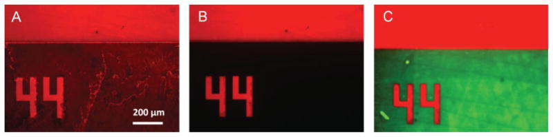
Fluorescent images of protein copatterning on PDMS using parylene. A: Initially, a Texas Red-BSA protein solution is incubated on the parylene membrane for 15–30 min. The protein (red) adsorbs both to the parylene and the exposed regions of the PDMS. B: After the parylene is peeled off, the adsorbed protein pattern remains on the substrate (red), while the unexposed regions are free of protein (black). C: A second protein solution of FITC-BSA (green) is incubated on the first pattern, selectively binding to the protein-free regions and creating a protein copattern. [Color figure can be viewed in the online issue, which is available at www.interscience.wiley.com.]
Reversible sealing of parylene on different substrates
To analyze the potential of parylene stencils for use as a widely applicable membrane for surface pattering, we tested the surface patterning capability of the parylene stencils on a variety of commonly used laboratory substrates including PDMS, polystyrene, and glass. Upon visual inspection, parylene stencils adhered to PDMS substrates strongly and uniformly. As a result, the protein patterns created on PDMS were clearly defined (Fig. 3). Although patterns could be consistently generated on polystyrene, as shown in Figure 4(A), polystyrene was less robust in sealing parylene stencils and required manual manipulation to increase adhesion. We observed that parylene stencils did not adhere to glass substrates. From these observations, we believe that parylene adhesion is regulated by hydrophobic interactions. This theory is supported by contact angle measurements of water on these surfaces: Parylene-C (96°), which is hydrophobic, adheres to PDMS (97°) and polystyrene (~90°)27 but not to untreated glass (14°). To increase the applicability of the parylene stencils, we examined the utility of changing the surface hydrophobicity of glass by a methacrylation process. Contact angle measurements showed that treatment of the glass surface with covalently bonded methacrylate groups increased the surface hydrophobicity from 14° for regular glass to 69° for methacrylated glass. Parylene stencils were able to reversibly seal to these treated glass surfaces, enabling the protein patterning [Fig. 4(B)]. It is noteworthy that only the side of the parylene stencil that is attached to the wafer after fabrication adhered to substrates. We believe this may be due to nanoscale irregularities introduced on the top surface of the parylene during the fabrication process, which both roughens this side and renders it hydrophilic.
Figure 4.

Fluorescent images of proteins patterned on (A) polystyrene, (B) methacrylated glass, and (C) curved PDMS. The success of these substrates in creating patterns is dependent on the formation of a tight reversible seal between the substrate and the parylene membrane upon contact. Glass slides did not provide a tight seal. We conclude that only hydrophobic surfaces, such as PDMS, polystyrene, and methacrylated glass, can be used for protein patterning with parylene. [Color figure can be viewed in the online issue, which is available at www.interscience.wiley.com.]
An advantage of the stencil based surface patterning is that it can be applied to curved surfaces. To examine this feature, we wrapped parylene membranes on cylindrical PDMS slabs and subsequently deposited FITC-BSA on the surfaces. Upon removal of the stencil, protein patterns were formed [Fig. 4(C)].
To examine the reusability of the parylene stencils, we performed 10 successive patterning processes with a single stencil. Consecutive patterns were highly conserved on PDMS [Fig. 5(A)] and polystyrene [Fig. 5(B)], revealing that parylene stencils are reusable. As long as the parylene stencil was dried between rounds, it was found to adhere equally well in all 10 rounds. Also, by using sharp tweezers, we found that it was possible to easily remove the stencils from a surface multiple times without damage to the stencil pattern features.
Figure 5.

Reusability of parylene membranes as a stencil for multiple protein patterning experiments. FITC-BSA was patterned on PDMS (A) and polystyrene (B) using a single parylene membrane for 10 different patterning experiments. The structural integrity of the membrane was easily preserved through the 10 experiments, as evidenced by the nearly identical protein patterns it produced. [Color figure can be viewed in the online issue, which is available at www.interscience.wiley.com.]
Cell patterning
Reusable parylene stencils can also be used to pattern cells. We were able to pattern NIH-3T3 fibroblasts [Fig. 6(A,B)], AML12 murine hepatocytes, and mouse embryonic stem cells (mES). To create these cell patterns, surfaces were initially treated with fibronectin (FN) using one of two treatment methods. In the first method, FN was incubated on the substrate prior to addition of the parylene stencil; while in the second method, the parylene was adhered to the substrate prior to incubation with FN. After incubation with FN, a cell suspension was incubated on top of the parylene stencil to allow cells to settle and attach to the surface. Subsequent removal of the parylene stencil revealed the micro-pattern of cells on the surface of the substrate. An important factor for generating robust cell patterns was the size of the holes in the parylene pattern. In general, higher pattern integrity was achieved with larger stencil features (>200 μm diameter) because cells, especially fibroblasts, elongated when they attached to a substrate, often stretching across a hole or attaching to both the parylene and the substrate. Despite this, it was possible to produce an array comprised of single cells by optimizing the pattern feature size. We found that a pattern with 40 μm diameter circles was optimum for creating single cell arrays of NIH-3T3 cells when the parylene stencil was lifted off, which demonstrates the potential of this approach for a variety of single-cell screening studies.
Figure 6.

Cell patterning on PDMS using parylene stencils. A,B: Phase contrast images of patterned NIH-3T3 fibroblasts after stencil removal. Substrate was initially coated with FN to increase adhesion. C–F: Cell cocultures of AML12 hepatocytes (blue) and NIH-3T3 fibroblasts (red). AML12 hepatocytes are patterned first, and viewed with phase contrast (C) and fluorescence (E) microscopy. Subsequently, NIH-3T3 cells are seeded, allowed to grow to confluence, and viewed with phase contrast (D) and fluorescence (F) microscopy. [Color figure can be viewed in the online issue, which is available at www.interscience.wiley.com.]
Controlling the microscale location of two different cell types in vitro is important in mimicking the cell–cell interactions of in vivo systems, such as spatial signaling and the degree of homotypic/heterotypic contact.28 Patterned cocultures of two or more cell types have been created using photolithography,28–32 microfluidics,9,33 elastomeric membranes,2,14,34 and layer-by-layer deposition of cell-adhesive materials.35,36 We fabricated patterned cocultures of two different cell types on a substrate using reversible adhesion of the parylene stencil. The substrate was initially patterned with the primary cell type [Fig. 6(C,E)], and subsequently incubated with the secondary cell type, allowing the cells to fill in all unoccupied spaces of the substrate [Fig. 6(D,F)]. The co-pattern of AML-12 hepatocytes (primary) surrounded by NIH-3T3 fibroblasts (secondary), stained with DAPI (blue) and PKH-26 (red) respectively, shows that the secondary cell type preferentially attached to the exposed substrate [Fig. 6(F)].
Recovery of parylene surfaces
To reuse parylene stencils adsorbed proteins or cells may need to be removed from the stencil. We used plasma cleaning to remove adsorbed proteins from parylene stencils. To determine the optimum cleaning time, we plasma treated parylene stencils for various periods of time and measured the relative change in fluorescence. We assumed that a change in fluorescence correlated to a degradation and loss of protein from the surface of the stencil. The results, as summarized in Figure 7, indicate that the relative amount of protein left on the stencil decreases with increased treatment duration. For cleaning parylene stencils after use in cell patterning, a combination of trypsinizing and plasma cleaning successfully restored the stencil (data not shown). We first incubated parylene stencils in trypsin to remove cells and then plasma cleaned to remove any secreted proteins. Cleaned parylene stencils were then reused for cell patterning, showing no observable variation from new stencils. These results demonstrate the potential for reusing these reversible parylene membranes in multiple patterning experiments and applications.
Figure 7.

Recovery of a parylene membrane by plasma treatment. A parylene membrane used in protein patterning adsorbs an amount of protein, which may inhibit its effectiveness in further experiments. Plasma treatment for 300 sec reduces this adsorbed protein concentration to the original value.
CONCLUSIONS
We have demonstrated a simple, robust, and potentially widely applicable approach for patterning biomolecules and cells by means of reversible adhesion of microfabricated parylene-C stencils. Parylene-C has previously been used to create biologically relevant patterns. However, these techniques are limited to a single use and allow patterning only on silicon and glass surfaces. We show that the parylene stencils can be reversibly sealed on a variety of materials. In addition, these 10-μm-thick stencils are mechanically stronger than the other dry polymer lift-off films, resulting in high structural integrity and reusability: through 10 successive rounds of protein patterning, including washing and drying, we observed no structural damage and obtained high pattern fidelity.
Reversible adhesion and reusability allows the copatterning of two different proteins on the same substrate, which has applications in tissue engineering and cell behavior studies.37–39 Copatterns of cells were also created with parylene stencils using similar techniques. The power of patterning with reversible parylene stencils lies in its applicability to a variety of pre-fabricated substrates. We have confirmed that parylene can adhere to and create protein patterns on hydrophobic surfaces such as PDMS, polystyrene and methacrylated glass. The precise control of biomolecular and cellular position afforded by this technology could be useful for tissue engineering constructs, high-throughput screening,40,41 and biosensors.42 Furthermore, the robustness of these parylene stencils could increase the dissemination and utilization of micro-patterning technology.
Acknowledgments
Contract grant sponsor: NIH; contract grant numbers: HL60435, DE16516
Contract grant sponsor: Institute for Soldier Nanotechnology; contract grant number: DAAD 19-02-D-2002
Contract grant sponsor: Coulter Foundation
Contract grant sponsor: Center for Integration of Medicine and Innovative Technology
Contract grant sponsor: Charles Stark Draper Laboratory
J.M.K. is supported by an NSERC postdoctoral fellowship. Y.L. is supported by an NDSEG fellowship.
References
- 1.Khademhosseini A, Langer R, Borenstein J, Vacanti JP. Micro-scale technologies for tissue engineering and biology. Proc Natl Acad Sci USA. 2006;103:2480–2487. doi: 10.1073/pnas.0507681102. [DOI] [PMC free article] [PubMed] [Google Scholar]
- 2.Folch A, Toner M. Microengineering of cellular interactions. Annu Rev Biomed Eng. 2000;2:227–256. doi: 10.1146/annurev.bioeng.2.1.227. [DOI] [PubMed] [Google Scholar]
- 3.Sims CE, Allbritton NL. Analysis of single mammalian cells on-chip. Lab Chip. 2007;7:423–440. doi: 10.1039/b615235j. [DOI] [PubMed] [Google Scholar]
- 4.James CD, Davis R, Meyer M, Turner A, Turner S, Withers G, Kam L, Banker G, Craighead H, Issacson M, Turner J, Shain W. Aligned microcontact printing of micrometer-scale poly-L-lysine structures for controlled growth of cultured neurons on planar microelectrode arrays. IEEE Trans Biomed Eng. 2000;47:17–21. doi: 10.1109/10.817614. [DOI] [PubMed] [Google Scholar]
- 5.Lahiri J, Ostuni E, Whitesides GM. Patterning ligands on reactive SAMs by microcontact printing. Langmuir. 1999;15:2055–2060. [Google Scholar]
- 6.Mrksich M, Dike LE, Tien J, Ingber DE, Whitesides GM. Using microcontact printing to pattern the attachment of mammalian cells to self-assembled monolayers of alkanethiolates on transparent films of gold and silver. Exp Cell Res. 1997;235:305–313. doi: 10.1006/excr.1997.3668. [DOI] [PubMed] [Google Scholar]
- 7.Renault JP, Bernard A, Juncker D, Michel B, Bosshard HR, Delamarche E. Fabricating microarrays of functional proteins using affinity contact printing. Angewandte Chemie Int Ed. 2002;41:2320–2323. doi: 10.1002/1521-3773(20020703)41:13<2320::AID-ANIE2320>3.0.CO;2-Z. [DOI] [PubMed] [Google Scholar]
- 8.Delamarche E, Bernard A, Schmid H, Bietsch A, Michel B, Biebuyck H. Microfluidic networks for chemical patterning of substrate: Design and application to bioassays. J Am Chem Soc. 1998;120:500–508. [Google Scholar]
- 9.Takayama S, McDonald JC, Ostuni E, Liang MN, Kenis PJA, Ismagilov RF, Whitesides GM. Patterning cells and their environments using multiple laminar fluid flows in capillary networks. Proc Natl Acad Sci USA. 1999;96:5545–5548. doi: 10.1073/pnas.96.10.5545. [DOI] [PMC free article] [PubMed] [Google Scholar]
- 10.Tan W, Desai TA. Microfluidic patterning of cells in extracellular matrix biopolymers: Effects of channel size, cell type, and matrix composition on pattern integrity. Tissue Eng. 2003;9:255–267. doi: 10.1089/107632703764664729. [DOI] [PubMed] [Google Scholar]
- 11.Andersson H, van den Berg A. Where are the biologists? Lab Chip. 2006;6:467–470. doi: 10.1039/b602048h. [DOI] [PubMed] [Google Scholar]
- 12.Suh KY, Seong J, Khademhosseini A, Laibinis PE, Langer R. A simple soft lithographic route to fabrication of poly(ethylene glycol) microstructures for protein and cell patterning. Biomaterials. 2004;15:557–563. doi: 10.1016/s0142-9612(03)00543-x. [DOI] [PubMed] [Google Scholar]
- 13.Khademhosseini A, Jon S, Suh KY, Tran TNT, Eng G, Yeh J, Seong J, Langer R. Direct Patterning of protein- and cell-resistant polymeric monolayers and microstructures. Adv Mater. 2003;15:1995–2000. [Google Scholar]
- 14.Folch A, Jo BH, Hurtado O, Beebe DJ, Toner M. Microfabricated elastomeric stencils for micropatterning cell cultures. J Biomed Mater Res. 2000;52:346–353. doi: 10.1002/1097-4636(200011)52:2<346::aid-jbm14>3.0.co;2-h. [DOI] [PubMed] [Google Scholar]
- 15.Yi SM, Jin SH, Lee JD, Chu CN. Fabrication of High-Aspect-Ratio Stainless-Steel Shadow Mask and its Application to Pentacene Thin-Film Transistors. J Micromech Microeng. 2005;15:263–269. [Google Scholar]
- 16.Kammer S, Wien S, Koch KP, Robitzki A, Stieglitz T. Biomed Tech. Suppl 1 Part 2. Vol. 47. Berl: 2002. [Coating material of parlene C as encapsulation material for biomedical micro-implants] pp. 823–826. [DOI] [PubMed] [Google Scholar]
- 17.Bienkiewicz J. Plasma-enhanced parylene coating for medical device applications. Med Device Technol. 2006;17:10–11. [PubMed] [Google Scholar]
- 18.Schmidt EM, Bak MJ, Christensen P. Laser exposure of Parylene-C insulated microelectrodes. J Neurosci Methods. 1995;62:89–92. doi: 10.1016/0165-0270(95)00060-7. [DOI] [PubMed] [Google Scholar]
- 19.Hong-seok N, Kyoung-sik M, Andrew C, Peter JH, Wong CP. Wafer bonding using microwave heating of parylene intermediate layers. J Micromech Microeng. 2004;14:625. [Google Scholar]
- 20.Tooker A, Meng E, Erickson J, Tai YC, Pine J. Biocompatible parylene neurocages. Developing a robust method for live neural network studies. IEEE Eng Med Biol Mag. 2005;24:30–33. doi: 10.1109/memb.2005.1549727. [DOI] [PubMed] [Google Scholar]
- 21.Noh HS, Choi Y, Wu C, Hesketh PJ, Allen MG. Rapid low-cost fabrication of parylene microchannels for microfluidic applications, Proc. 12th Int. Conf on Solid-State Sensors, Actuators, and Microsystems, Transducers’03; June 8–12, 2003; pp. 798–801. [Google Scholar]
- 22.Lotters JC, Olthuis W, Veltink PH, Bergveld P. The mechanical properties of the rubber elastic polymer polydimethylsiloxane for sensor applications. J Micromech Microeng. 1997;7:145. [Google Scholar]
- 23.Ilic B, Craighead HG. Topographical patterning of chemically sensitive biological materials using a polymer-based dry lift off. Biomed Microdevices. 2000;2:317. [Google Scholar]
- 24.Orth RN, Kameoka J, Zipfel WR, Ilic B, Webb WW, Clark TG, Craighead HG. Creating biological membranes on the micron scale: forming patterned lipid bilayers using a polymer lift-off technique. Biophys J. 2003;85:3066–3073. doi: 10.1016/S0006-3495(03)74725-0. [DOI] [PMC free article] [PubMed] [Google Scholar]
- 25.Moran-Mirabal JM, Edel JB, Meyer GD, Throckmorton D, Singh AK, Craighead HG. Micrometer-sized supported lipid bilayer arrays for bacterial toxin binding studies through total internal reflection fluorescence microscopy. Biophys J. 2005;89:296–305. doi: 10.1529/biophysj.104.054346. [DOI] [PMC free article] [PubMed] [Google Scholar]
- 26.Pal R, Sung KE, Burns MA. Microstencils for the patterning of nontraditional materials. Langmuir. 2006;22:5392–5397. doi: 10.1021/la052811s. [DOI] [PubMed] [Google Scholar]
- 27.Fletcher M, Marshall KC. Bubble contact angle method for evaluating substratum interfacial characteristics and its relevance to bacterial attachment. Appl Environ Microbiol. 1982;44:184. doi: 10.1128/aem.44.1.184-192.1982. [DOI] [PMC free article] [PubMed] [Google Scholar]
- 28.Bhatia SN, Balis UJ, Yarmush ML, Toner M. Effect of cell-cell interactions in preservation of cellular phenotype: Cocultivation of hepatocytes and nonparenchymal cells. FASEB J. 1999;13:1883–1900. doi: 10.1096/fasebj.13.14.1883. [DOI] [PubMed] [Google Scholar]
- 29.Bhatia SN, Balis UJ, Yarmush ML, Toner M. Microfabrication of hepatocyte/fibroblast co-cultures: Role of homotypic cell interactions. Biotechnol Prog. 1998;14:378–387. doi: 10.1021/bp980036j. [DOI] [PubMed] [Google Scholar]
- 30.Bhatia SN, Balis UJ, Yarmush ML, Toner M. Probing heterotypic cell interactions: Hepatocyte function in microfabricated co-cultures. J Biomater Sci Polym Ed. 1998;9:1137–1160. doi: 10.1163/156856298x00695. [DOI] [PubMed] [Google Scholar]
- 31.Bhatia SN, Toner M, Tompkins RG, Yarmush ML. Selective adhesion of hepatocytes on patterned surfaces. Ann N Y Acad Sci. 1994;745:187–209. doi: 10.1111/j.1749-6632.1994.tb44373.x. [DOI] [PubMed] [Google Scholar]
- 32.Bhatia SN, Yarmush ML, Toner M. Controlling cell interactions by micropatterning in co-cultures: hepatocytes and 3T3 fibroblasts. J Biomed Mater Res. 1997;34:189–199. doi: 10.1002/(sici)1097-4636(199702)34:2<189::aid-jbm8>3.0.co;2-m. [DOI] [PubMed] [Google Scholar]
- 33.Ostuni E, Kane R, Chen CS, Ingber DE, Whitesides GM. Patterning mammalian cells using elastomeric membranes. Langmuir. 2000;16:7811–7819. [Google Scholar]
- 34.Folch A, Toner M. Cellular micropatterns on biocompatible materials. Biotechnol Prog. 1998;14:388–392. doi: 10.1021/bp980037b. [DOI] [PubMed] [Google Scholar]
- 35.Fukuda J, Khademhosseini A, Yeh J, Eng G, Cheng J, Farokhzad OC, Langer R. Micropatterned cell co-cultures using layer-by-layer deposition of extracellular matrix components. Biomaterials. 2006;27:1479–1486. doi: 10.1016/j.biomaterials.2005.09.015. [DOI] [PubMed] [Google Scholar]
- 36.Khademhosseini A, Suh KY, Yang JM, Eng G, Yeh J, Levenberg S, Langer R. Layer-by-layer deposition of hyaluronic acid and poly-L-lysine for patterned cell co-cultures. Biomaterials. 2004;25:3583–3592. doi: 10.1016/j.biomaterials.2003.10.033. [DOI] [PubMed] [Google Scholar]
- 37.Chen CS, Mrksich M, Huang S, Whitesides GM, Ingber DE. Geometric control of cell life and death. Science. 1997;276(5317):1425–1428. doi: 10.1126/science.276.5317.1425. [DOI] [PubMed] [Google Scholar]
- 38.Lehnert D, Wehrle-Haller B, David C, Weiland U, Ballestrem C, Imhof BA, Bastmeyer M. Cell behaviour on micropatterned substrata: Limits of extracellular matrix geometry for spreading and adhesion. J Cell Sci. 2004;117 (Part 1):41–52. doi: 10.1242/jcs.00836. [DOI] [PubMed] [Google Scholar]
- 39.Barbucci R, Lamponi S, Magnani A, Pasqui D. Micropatterned surfaces for the control of endothelial cell behaviour. Biomol Eng. 2002;19:161–170. doi: 10.1016/s1389-0344(02)00022-9. [DOI] [PubMed] [Google Scholar]
- 40.MacBeath G, Schreiber SL. Printing proteins as microarrays for high-throughput function determination. Science. 2000;289(5485):1760–1763. doi: 10.1126/science.289.5485.1760. [DOI] [PubMed] [Google Scholar]
- 41.Khademhosseini A, Yeh J, Eng G, Karp J, Kaji H, Borenstein J, Farokhzad OC, Langer R. Cell docking inside microwells within reversibly sealed microfluidic channels for fabricating multiphenotype cell arrays. Lab Chip. 2005;5:1380–1386. doi: 10.1039/b508096g. [DOI] [PubMed] [Google Scholar]
- 42.Jain KK. Current status of molecular biosensors. Med Device Technol. 2003;14:10–15. [PubMed] [Google Scholar]