

Abstract
Numerous high-quality, volume mesh-generation systems exist. However, no strategy can address all geometry situations without some element qualities being compromised. Many 3D mesh generation algorithms are based on Delaunay tetrahedralization which frequently fails to preserve the input boundary surface topology. For biomedical applications, this surface preservation can be critical as they usually contain multiple material regions of interest coherently connected. In this paper we present an algorithm as a post-processing method that optimizes local regions of compromised element quality and recovers the original boundary surface facets (triangles) regardless of the original mesh generation strategy. The algorithm carves out a small sub-volume in the vicinity of the missing boundary facet or compromised element, creating a cavity. If the task is to recover a surface boundary facet, a natural exit hole in the cavity will be present. This hole is patched with the missing boundary surface face first followed by other patches to seal the cavity. If the task was to improve a compromised region, then the cavity is already sealed. Every triangular facet of the cavity shell is classified as an active face and can be connected to another shell node creating a tetrahedron. In the process the base of the tetrahedron is removed from the active face list and potentially 3 new active faces are created. This methodology is the underpinnings of our last resort method. Each active face can be viewed as the trunk of a tree. An exhaustive breath and depth search will identify all possible tetrahedral combinations to uniquely fill the cavity. We have streamlined this recursive process reducing the time complexity by orders of magnitude. The original surfaces boundaries (internal and external) are fully restored and the quality of compromised regions improved.
1 Introduction
Finite element method is a versatile tool that tackles various problems in multiple engineering fields such as structure design, Bioengineering, MEMS and Nanoscience [5, 19, 20, 38, 59]. Discretizing the domain of the problem is an essential step to FE method. Adaptive problem solving strategies frequently require automated (re)generation and modification of the mesh in order to optimize various parameters in the problem and solution. For productivity reasons a fully automated mesh generator is a must [41], and historically, problems encountered in the mesh regeneration process are far more difficult than the rest of simulation process [43].
Post-processing a mesh is often a necessary step to ensure element quality. This stage is paramount to success of applications using the mesh. Each mesh can be examined for various quality measures such as element shape measures (minimum solid angle, radius ratio ρ and gamma coefficient γ [30]), regularity measures [8] and insphere deformation [25]. The accuracy and outcome of FE solutions rely on the quality of the mesh. For example dihedral angles of a tetrahedron in a mesh can have significant impacts on either precision of computations or the conditions of the stiffness matrix [13, 47]. Frequently, a finite element implementation requires the mesh to preserve the original defining boundary topology. This requirement is critical for adaptive remeshing of a sub-volume, or a multiple material volume coherently connected [46].
Delaunay triangulation is a favored approach in creating 2D meshes due to its inherent properties. For example, Delaunay triangulation tends to create well-shaped elements by maximizing the minimum interior angle over the domain [51]. The elements are also suitable for use in interpolation [47, 52] as well as refinement methods that can help generate meshes with provably good properties [10, 32, 12, 44].
The highly successful 2D Delaunay mesh generation strategies provided strong momentum for a 3D extension. Delaunay tetrahedralization has been used in [40] to simulate respiratory gating which helps diagnosticians overcome problems with artifacts in SPECT imaging method due to breathing motion. Sullivan and Zhang simulated 3D contaminant and fate transport of benzene for groundwater flow situations experiencing semi-discontinuous permafrost [53]. Quad-tree [60], Delaunay triangulation, advancing front [28] and sphere packing [49] are most common methods of mesh creation, out of which Delaunay is being used widely for establishing the connectivity [27, 57, 4, 42, 55, 1, 31, 3]. Unfortunately Delaunay tetrahedralization lacks several of the inherent qualities noted in the 2D triangulation. 2D Delaunay maximizes the minimum angle in the triangulation [23], minimizes the largest circumcircle and minimizes the largest min-containment circle1[9]. Unfortunately the first two properties can not be extended to higher dimensions, albeit the last one is proved to be a general property of Delaunay triangulations [36]. Additionally, 3D Delaunay triangulation does not always exist for every polyhedron [39] whereas all 2D polygons have a Delaunay triangulation.
Delaunay tetrahedralization can have undesirable side effects: poor quality elements and missing input boundaries. Different approaches have been developed to address these issues including introduction of new vertices at the centroids or the center of circumcircle of problematic elements or using advancing front methods [15, 29, 56]. Another significant difference is that in 2D the edge elements are preserved in the triangular mesh provided a constrained Delaunay was used. However, in 3D the triangular surfaces are not always guaranteed even if a constrained Delaunay is used [48]. This situation can raise problems for FEM applications. For instance, maintaining simplexes of the boundary is necessary for applying boundary conditions imposed by the application. Similarly, respecting the interface between two biological tissues with different diffusion coefficients, when solving a material propagation problem, is required.
Post-processing or clean-up of a mesh generally falls into two categories: smoothing and topological optimizations [34]. The former is relocating one or more nodes in order to increase quality measures, while the latter is changing the connectivity of the nodes in order to form better elements. During last two decades, extensive work has advanced these post-processing tools significantly. [2, 14, 37, 16]
However, recovery of the original physical boundaries (internal and external) has remained illusive. This paper presents a successful strategy to recover all physical boundaries regardless of the original technique used to create the mesh. A natural underlying mechanism within this approach is the optimization of element qualities in the vicinity. This latter feature can be applied throughout the mesh.
2 Existing Approaches
As mentioned previously, boundary recovery is necessary for meshes created by Delaunay tetrahedralization and it can be difficult for certain domain boundaries [46]. Studies and research on boundary recovery mainly use two strategies in order to mitigate the problem: (a) Breaking up input boundary constraints and (b) a series of edge and face swaps/flips. In general there are three different approaches: conforming Delaunay, almost Delaunay and constrained Delaunay tetrahedralization [46].
Conforming Delaunay
Conforming Delaunay has been presented in several works as a technique to recover the physical boundary topology [33, 7, 18]. In this method additional vertices are introduced to the mesh. The methods differ based on the interior node insertions locations and criterion to minimize the number of point insertions. These strategies do maintain the Delaunay property of empty circumspheres. Upon successful completion of this procedure, the boundary facets are basically subdivided into several smaller ones. That is, the original surface facets have been subdivided. Consequently, they are not suitable for remeshing a sub-region of a domain. Additionally, these algorithms can create extremely small tetrahedrons. Liu shows some cases that fail the above method [24].
Almost Delaunay
Several researchers retrieve the domain boundary by inserting additional points wherever a face of the mesh intersects a missing segment or an edge of the triangulation intersects a missing facet [21, 17, 57]. Again the faces are recovered as a union of smaller faces. If the input physical boundary was defined as a polygon and not necessarily as a single triangle, this technique is valuable. However, it still produces an inconsistent mesh if the recovery of the boundary was an interior boundary. Within this category two investigations have developed strategies to recover the boundary without introducing new nodes. Originally, Wu developed the first ‘Last Resort’ code in 2001 [58]. The system could recover the original boundaries, but the time complexities were considerable. Recently, a small polyhedron reconnection (SPR) operation was presented that reconstructs the original input boundary without adding new nodes [26]. This sphere-packing method packs spheres based on a mesh sizing function. Selection of this sizing function is important for their algorithm to work well. In this category ‘Almost Delaunay’, the Delaunay property is not fully preserved. The elements are split such that they introduce new vertices without removing existing faces and edges of the domain boundary. Although this method does not fully maintain Delaunay property, it is very common in practical applications.
Constrained Delaunay tetrahedralization
In this method, after creating Delaunay tetrahedralization of the input vertices, which usually creates a convex hull encompassing the domain, the missing edges of the boundary are identified and new vertices are inserted to recover them. At this point the Delaunay tetrahedrons are replaced by constrained Delaunay tetrahedrons which recovers the missing faces. Usually these algorithms first generate a constrained triangulation of input boundary using different methods such as [6]. Then either a gift wrapping algorithm, sweep algorithm or incremental face insertion is used to construct constrained Delaunay tetrahedrons [45, 46, 54].
3 Algorithm
We present a different approach that does not involve introducing new vertices to the mesh. It is purely based on altering the topology in a limited section of the mesh. As stated previously, there are works that include changing the connectivity of the nodes in order to recover the boundary edges and/or faces [57, 11, 21]. Those methods usually limit the alterations to edge swaps involving the missing physical face. For instance, Figure 1 shows common topological transformations involving edge flips. Some techniques insert new points to the mesh to force a different mesh configuration as a means of recovering the original physical face [33, 18], but frequently, this produces a composite surface and is not suitable for interior boundary recoveries. Our corrective approach is an edge/face swap strategy that expands the number of tetrahedrons traditionally involved in the connectivity alteration process. This feature results in multiple configuration options to recover the physical boundary facets simultaneous with an improved quality mesh in that particular region.
Figure 1.
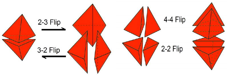
Typical connectivity transformations involving 2 to 4 elements.
Our strategy carves out a cavity, caps the surface with the previously missing physical faces, if necessary, and subsequently fills the void with tetrahedrons. It is based on a fully exhaustive branching algorithm, hence dubbed last resort [58]. However, several algorithm improvements as well as performance optimizations have reduced the search time by orders of magnitude. Consequently, the last resort post-processing strategy is a practical plug-in for most mesh generation systems. Since all the possible topological configurations are examined, we not only recover missing physical boundaries but also have the potential to improve element qualities in the vicinity.
The next section delineates the last resort algorithm followed by its use to recover missing physical boundaries.
3.1 Last Resort
Modifying a sub-volume of a mesh is always in high demand as a post-processing stage. It can be used to recover original boundary topologies of a domain or help improve the quality of a mesh. A few degenerate elements, in an otherwise quality mesh, can compromise the reliability and accuracy of FEM results. Re-meshing just a sub-volume of that mesh can avoid repeating the entire meshing process and save computational resources. The last resort algorithm performs this task. Consider an interior element of compromised quality. The routine identifies the element, deletes it, and all neighboring tetrahedrons that share a common node. This carved out sub-volume creates a cavity that is closed. Each cavity shell triangle is considered an active surface initially. The system considers all possible tetrahedrons that can be formed using an active cavity shell facet and selects the best one based on a quality criterion. This tetrahedron will, at minimum, retire one of the original boundary's facets and potentially introduce three new active shell faces. This iterative process continues until the sub-volume is filled with consistent, conforming tetrahedrons.
Simply searching for the optimal solution using this method is inefficient. If we assume every N face can produce N − 1 elements at every level, then the number of possible solutions to be tested is in the order of O(N!). In following section we will show how to drastically improve the efficiency of algorithm by intelligently choosing which route to take in order to obtain an optimal solution in less time and make the algorithm a practical approach for mesh improvement problems.
3.1.1 Description
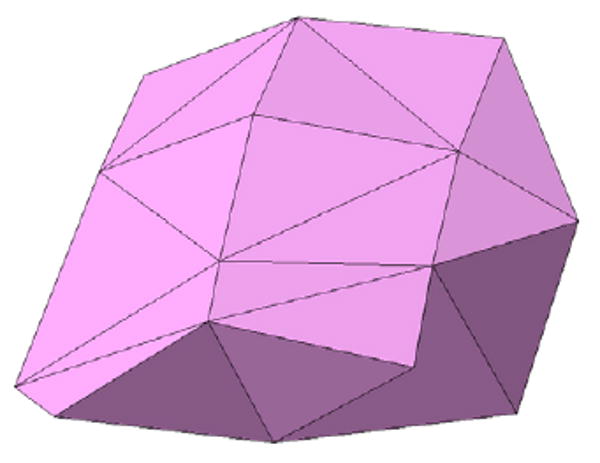
We describe the algorithm for a 3D case but the example illustrations are in 2D for clarity purposes. Assume a part of a mesh contains a low quality element q ≤ ηe, Figure 2(a). We create a closed cavity by removing the low quality element (marked as X) and its surrounding elements (marked as Y), Figure 2(b). In 3D counterpart, this will be a closed surface, Ψi. The algorithm continues with the boundary surface enclosing the sub-domain to be meshed. This boundary can also include scattered interior points which will be used in the meshing process. All the entities of the closed cavity are considered active 3D faces (2D edges) or nodes (Figure 2(c)). Assume a boundary surface of Nf faces and Nscattered interior scattered points or n = Nf + Nscattered total nodes. Given that there exists n points in the original cavity, we can form mi different tetrahedrons using face Fi(1 ≤ i ≤ Nf) and another point (Figure 2(d)), where
Figure 2.
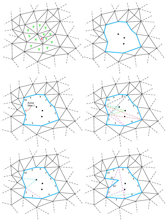
(Left to Right, top to bottom) (a) Original mesh with a low quality element. (b) Carving out all the elements containing any vertices of the bad element. (c) Simplexes (active edges and isolated nodes) to be used for triangle formation. (d) Different possibilities of element formation, of which some are not viable due to either quality or geometry constraints. (e) Insertion of any possible element might introduce 1 or 2 new active edges. (f) Placing the new element creates a new set of active edges and the process continues by using another edge from list of active simplexes.
| (1) |
As shown in Figure 2(d), not all mi possible formations are viable since some do not meet the quality criterion or their formation invalidates the continuity of the mesh. Next, using another active face Fi+1 in the current boundary surface Ψi, we examine how many valid tetrahedral elements, whose quality is greater than ηe, can be formed: mi+1. If mi+1 < mi, the algorithm discards face Fi as a potential candidate for generating a tetrahedron at that level and substitutes it with Fi+1. Note that as in Figure 2(e), some of element formations might produce different number of new active edges or active faces in 3D case. The iteration continues and discards each face Fj if mj ≥ mmin, where
| (2) |
The result is a face with the least number of potential offspring tetrahedrons, out of which the best quality tetrahedron is chosen (Figure 3). The algorithm then inserts that tetrahedron into the domain causing removal of at least one boundary facet and creating potentially three new active faces. This process generates a different sub-volume encapsulated by a new boundary surface ψi, on which the same aforementioned process can be performed recursively (shown for 2D in Figure 2(f) and in Figure 4 for 3D case.)
Figure 3.
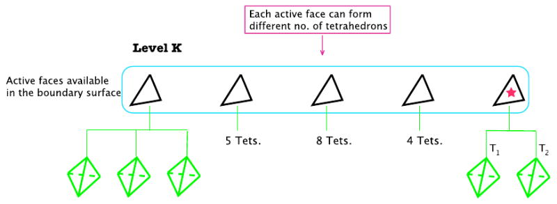
Each active triangle in Level K has the potential of producing different number of tetrahedrons. Every possible tetrahedron is examined for quality. The active face with the least number of possible tetrahedrons is chosen to form an element.
Figure 4.
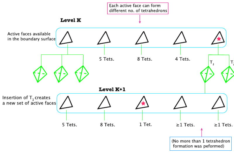
Insertion of tetrahedron T1 to the sub-volume will create a new set of active faces. This moves the algorithm one level down (K + 1). The new active triangles are now ready to be examined for their possible tetrahedron formations.
As Figure 2 shows, removal of elements can leave behind some internal nodes within the carved out region that do not connect to any other simplex. This makes no difference in how last resort makes use of them. All the simplexes involved in the carved out region are examined in the process of forming all possible tetrahedrons regardless of their isolation state and no element is formed if it contained any node, including the isolated ones.
This process continues until there only exists four faces which form the last tetrahedral element and the entire domain is populated. Once one complete solution is achieved, we can trace back our steps to mother face set Ψi and try a different route. Upon successful completion of each try, the algorithm can compare the quality of all the solutions, either based on minimum element quality or an average quality of elements, in order to choose the desired mesh. This can also be done exhaustively to examine all possible connectivities, but this option is not realistic since it can be time consuming. Figure 2 shows an example of the steps described above, depicted in 2D for simplicity in illustration.
If in any given sub-surface ψi, one of the triangular facets, Ffailed, fails to produce any acceptable tetrahedral element, that step is considered void and none of the other available facets of ψi are examined (Figure 5). At this point, the algorithm goes back one step and tries the previous sub-surface Ψi, using a different triangular facet to form an element (Figure 6).
Figure 5.
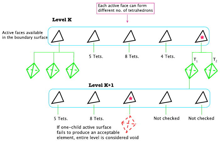
If one of the active faces fails to produce an acceptable tetrahedron, the algorithm will not check additional faces on that level and that branch is tagged as broken.
Figure 6.
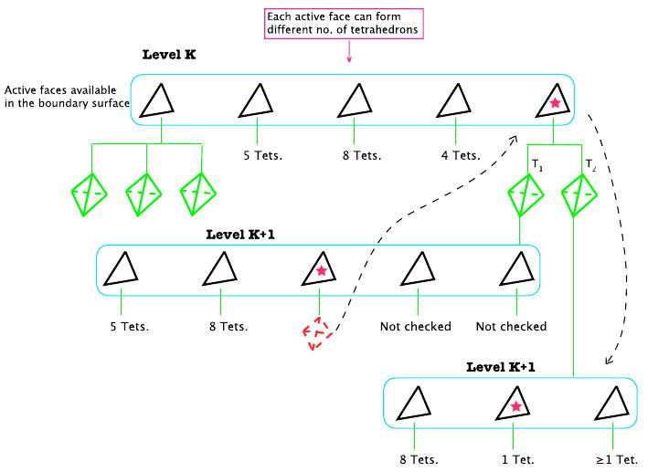
A broken branch forces algorithm to consider other active faces in previous level (K). Here tetrahedron T2 from previous level is considered and a new level of active faces is created in the same way as Figure 3.
If we had used other faces of a failed ψi and created a different tetrahedron path, the resulting sub-surface still contains Ffailed and eventually it must be connected to one of the available points in the current point set but we have already established that such connectivity was not acceptable. Algorithm 1 flowcharts the last resort process. As discussed previously, performing an exhaustive search along only one branch of the tree in Figure 3 is of the order O(N!). Therefore the upper bound for number of operations necessary for an exhaustive search can be expressed as:
| (3) |
However the selective approach for the path descent down the search tree will reduce the upper bound of required operations to:
| (4) |
where N is the total number of original active faces in the carved out surface Ψ.
| Algorithm 1 Last Resort Flowchart | |
| 1: | Last_Resort_Algorithm(Ψi,ηe) |
| 2: | Ψi ← Boundary surface |
| 3: | ηe ← Minimum desired element quality |
| 4: | Output: PotentialMeshj |
| 5: | if Ψi has only 4 remaining faces then |
| 6: | Form the tetrahedral element e |
| 7: | PotentialMeshj ← e |
| 8: | return PotentialMeshj |
| 9: | end if |
| 10: | for all Faces, Fi, in current boundary surface Ψi do |
| 11: | if Fi can produce at least one acceptable tetrahedron whose quality q > ηe then |
| 12: | Ni ← number of possible tetrahedrons |
| 13: | if Ni < Nmin then |
| 14: | Nmin← Ni |
| 15: | Insert Fi to the top of Listfaces stack and push all the current faces down |
| 16: | end if |
| 17: | else |
| 18: | return NULL |
| 19: | end if |
| 20: | end for |
| 21: | while Listfaces ≠ ∅ do |
| 22: | Pick the face from top of the Listfaces stack andform its best tetrahedron e |
| 23: | Update Ψi boundary surface based on insertion of element e |
| 24: | Assign the new boundary to ψi |
| 25: | Call M ← Last_Resort_Algorithm(ψi,ηe) |
| 26: | if M is not NULL then |
| 27: | PotentialMeshj = PotentialMeshj ∪ M |
| 28: | return PotentialMeshj |
| 29: | else |
| 30: | Remove the top enitity in Listfaces stack and continue |
| 31: | end if |
| 32: | end while |
| 33: | return NULL |
3.2 Boundary Recovery
As mentioned previously, our goal is to recover the original surface topology of any given tetrahedral mesh regardless of how it was created. This task requires having the original boundary surface Θ, and the mesh Γ. The idea is to identify a missing face and remove all the elements that are connected to its three vertices, creating an open cavity in the mesh. The cavity will not be sealed since the elements associated with the missing face nodes were removed. The missing face is recovered and added to the active cavity surface shell and additional triangles are added to seal the cavity if necessary. The resulting closed surface is now ready to be passed to our last resort operation to create new tetrahedral elements that can be directly inserted into the parent mesh.
As a preliminary step, we remove all elements of the parent mesh whose centroid fails the Θ inclusion test. This rudimentary constrained Delaunay recovery is a necessary step for meshes created by Delaunay method as it produces a mesh covering the convex hull of Θ. All boundary faces of the mesh Γ are identified. These faces are contained in only one tetrahedron of the same material type. We refer to this set of faces as numerical boundary faces Ω, as oppose to physical boundary Θ. The faces in Θ are compared against the Ω list to identify the missing physical faces of interior or exterior boundaries.
For every missing face Mi, we identify its 3 vertices and tag all the tetrahedrons whose vertex list contains at least one of the 3 vertices. Concatenating the tagged tetrahedrons creates a shell ψi which is not necessarily a closed surface, meaning that there are edges of triangular facets on ψi that only belong to one boundary face. Note that ψi is a piecewise linear complex with the following extra restriction.
Denoting the triangular sub-surface as ψi, we can write:
| (5) |
where δi's are the faces of the carved-out sub-volume. Given an edge segment λ shared by two triangular facets δm and δn, then A must be empty, where A is set of all faces containing λ and:
| (6) |
Using the same notation we call ψi non-closed if n(B) = 1 where
| (7) |
where Λ is an edge segment. This implies that ψi, i.e. the carved out volume, is a boundary separating only two different regions and none of its triangular edges can be shared by more than two triangular faces.
The perimeter of a possible hole on surface of ψi can also contain a set of scattered nodes depending upon the extent of tetrahedral element deletion. Denoting all these simplexes as K, we cover the hole using edges and points from K. First Mi is recovered forming the original surface triangle. The algorithm also searches for other possible missing faces that can be reproduced using the simplexes available in K, removing them from K upon a successful recovery. Once the cavity is capped any remaining nodes (isolated during the carve out process) become part of the set of simplexes to be sent to last resort algorithm.
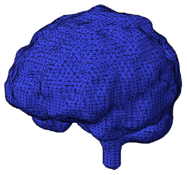
At this stage if the hole is completely covered, the sealed cavity is sent to our last resort algorithm to be meshed. Otherwise the remaining entities in K are examined to create new boundary faces in order to stitch up the hole. Figures 7 to 11 show an example of recovering a boundary face on a brain mesh. A pseudo code for recovery of the original surface boundary faces is provided in Algorithm 2.
Figure 7.
A tetrahedral mesh of an inverted human brain generated using 3D Delaunay algorithm.
Figure 11.
The output of last resort is inserted back to the original mesh with no inconsistencies since last resort preserves the cavity shell with fidelity.
The use of last resort on the closed surface ψi requires providing a desired quality value. A wide range of quality measures for tetrahedral elements has been devised. We chose to use the volume ratio quality, which measures the ratio of a given tetrahedron to that of a unilateral one.
If an acceptable quality submesh cannot be created via the last resort algorithm, the failure is overwhelmingly related to a flawed or poor quality segment of the physical boundary facets. Introducing new internal nodes would rarely rectify this situation containing flawed boundary facets. The last resort algorithm is exhaustive. Consequently, every possible connection, independent of Delaunay, is examined given the existing node deployment. If a satisfactory submesh cannot be created the user is notified of the root cause of problem so corrective measures can be taken. It should be noted that we have not encountered cases similar to [39] where the quality of facets of polyhedron is acceptable but no Delaunay tessellation was possible due to topology of boundary.
4 Results
This post-processing method has been used on volume meshes generated with different methods: SPMESH [61], offset normal method [22] and Tetgen [50]. Our application is associated with alternative breast imaging strategies [35]. Meshes in Figure 12 and Figure 13 show a brain and a breast mesh. The breast tissue in Figure 13 is deformed due to the various imaging probes being applied to the tissue [35].
Figure 12.
A volume mesh of a human brain.
Figure 13.

A volume mesh of a human breast.
Test case 1 included the brain mesh which had 17,312 triangles and 8,658 nodes in the original physical boundary surface. 6,022 surface triangles were not present in the final volume mesh of 142,167 tetrahedrons. The parent mesh and surface mesh were sent to the last resort boundary recovery post processor. All missing surface facets were recovered such that the 17,312 original surface triangles were part of the final volume mesh. The updated volume mesh was subsequently sent to the last resort quality improvement postprocessor. The overall quality was improved a small amount qavg = 0.410→qavg = 0.421, however more importantly 1621 elements whose qualities were virtually unacceptable were rectified. (The quality measure used here was a volume ratio similar to [30]). We should mention that the quality of input original mesh was not optimum and 817 faces out of 17312 had an area quality qarea < 0.1 which affects the improvement results.
In test case 2, a breast mesh was used containing 4,824 original boundary facets. The volume mesh was created using Tetgen containing 37,486 tetrahedral elements after removing the convex hull. The volume mesh was missing 579 original boundary faces which were all recovered after the mesh was post-processed. After returning from the last resort quality improvement post-processor the average quality was increased from qavg = 0.416 to qavg = 0.427. All 60 sliver and void elements were removed.
| Algorithm 2 Boundary Recovery | |
| 1: | BoundaryRecovery(Γ,Θ) |
| 2: | Γ = Tetrahedral mesh |
| 3: | Θ = Original/Desired Boundary mesh |
| 4: | Output: Constrained Delaunay of Γ (an almost Delaunay mesh) |
| 5: | Ω ← Extract numerical boundary faces of Γ by considering faces that only belong to one tetrahedron |
| 6: | M ← Θ ∩ Ω′ {Find list of missing faces} |
| 7: | for all Faces, Mi, in missing faces list M do |
| 8: | e ← Find all tetrahedral elements that share at least one of the vertices of Mi |
| 9: | Concatenate all members of e, leaving only their exterior surface → ψ |
| 10: | if ψ is non-closed surface then |
| 11: | K ← All the vertices and edges of the hole |
| 12: | Construct missing face Mi as well as any additional missing faces in neighbourhood using members of K. Remove all the members of K used in construction of missing faces. |
| 13: | if K ≠ θ then |
| 14: | Cover the hole by creating new numerical faces by using simplexes of K |
| 15: | end if |
| 16: | end if |
| 17: | Meshi = Call Last_Resort_Algorithm(Ψi,ηe) |
| 18: | if Last Resort was successful then |
| 19: | Insert Meshi back to Γ |
| 20: | else |
| 21: | Move Mi to the bottom of missing face list M |
| 22: | end if |
| 23: | if M = ∅ or we have tried all missing faces in M then |
| 24: | break the loop |
| 25: | end if |
| 26: | end for |
| 27: | Return Modified Γ |
5 Conclusion
A post-processing tool was presented that recovers the original surface boundary for both interior and exterior boundaries using local transformations in connectivity rather than extra vertex insertions. This ability was generally lacking in the field, yet of critical importance for remeshing a sub-zone of a large parent mesh or replacement of a material region. Our proposed method can handle any type of volume mesh generated by various methods and recover the initial physical boundary. To achieve this, we introduced last resort, an efficient search algorithm capable of creating quality grids using a closed polyhedron. Missing boundary faces of the given mesh are identified and their neighboring tetrahedral elements are removed creating an open cavity. The hole on the cavity, resulted from removal of the rogue faces, is covered using all possible physical boundary faces that were missing in this region. The sealed cavity is passed to last resort to create a sub-mesh that can be inserted directly into the parent mesh. We have been successfully using this approach in biomedical applications and alternative tissue imaging applications which use a variety of mesh generations systems.
Figure 8.
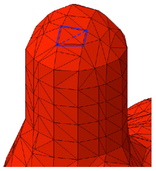
Detail of mesh where two of the original input boundary faces were missing (shown as blue lines).
Figure 9.
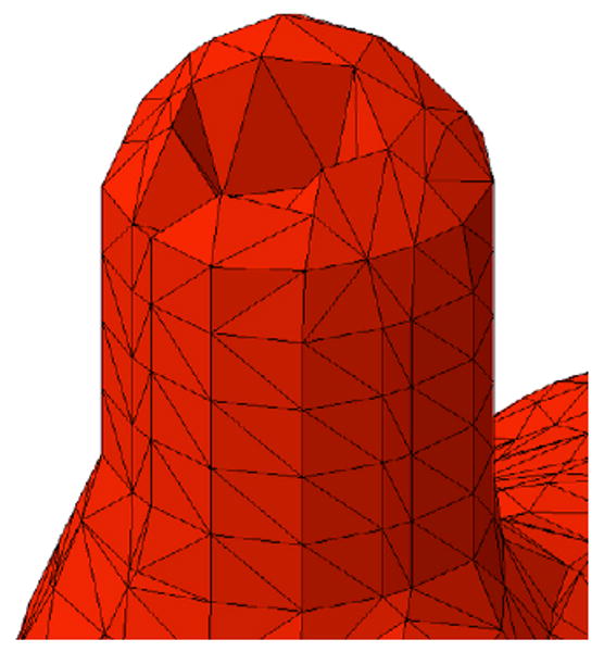
All the tetrahedrons containing one of the missing faces vertices are removed from mesh.
Figure 10.
The carved out volume interface with mesh along with restored missing faces are used to seal the cavity in the mesh. This creates a closed surface suitable for last resort algorithm.
Acknowledgments
This work was supported in part by NIH P01CA080139-08 award.
Footnotes
Min-containment circle of a triangle is the smallest circle that contains it and is not necessarily its circumcircle
Publisher's Disclaimer: This is a PDF file of an unedited manuscript that has been accepted for publication. As a service to our customers we are providing this early version of the manuscript. The manuscript will undergo copyediting, typesetting, and review of the resulting proof before it is published in its final citable form. Please note that during the production process errors may be discovered which could affect the content, and all legal disclaimers that apply to the journal pertain.
References
- 1.Baker TJ. Automatic mesh generation for complex three-dimensional regions using a constrained Delaunay triangulation. Engineering with Computers. 1989 Summer–Fall;5(34):161–75. [Google Scholar]
- 2.Bank RE, Sherman AH. Refinement algorithms and data structures for regular local mesh refinement. Scientific Computing. 1983:3–17. [Google Scholar]
- 3.Borouchaki H, George PL, Lo SH. Optimal Delaunay Point Insertion. International Journal for Numerical Methods in Engineering. 1996 Oct;39(20):3407–3437. [Google Scholar]
- 4.Borouchaki H, Lo SH. Fast Delaunay triangulation in three dimensions. Computer Methods in Applied Mechanics and Engineering. 1995 Dec;128(12):153–167. [Google Scholar]
- 5.Bro-Nielsen M. Finite element modeling in surgery simulation. Proceedings of the IEEEE. 1998 Mar;86(3):490–503. [Google Scholar]
- 6.Chew LP. Constrained delaunay triangulations. Algorithmica. 1989;4(1):97–108. [Google Scholar]
- 7.Cohen-Steiner D, Verdiere EC, Yvinec M. Conforming Delaunay triangulations in 3D. Computational Geometry-Theory and Applications. 2004 Jun;28(23):217–233. [Google Scholar]
- 8.Dannelongue HH, Tanguy PA. 3-dimensional adaptive finte-element computations and applications to non-newtonian fluids. International Journal for Numerical Methods in Fluids. 1991;13(2) [Google Scholar]
- 9.D'Azevedo EF, Simpson RB. On optimal interpolation triangle incidences. SIAM Journal on Scientific and Statistical Computing. 1989;10:1063–1075. [Google Scholar]
- 10.Dey TK, Bajaj CL, Sugihara K. On good triangulations in three dimensions. Int J Comput Geom Appl. 1992;2(1):75–95. [Google Scholar]
- 11.Du Q, Wang D. Constrained boundary recovery for three dimensional Delaunay triangulations. International Journal for Numerical Methods in Engineering. 2004;61:1471–1500. [Google Scholar]
- 12.Edelsbrunner H, Li XY, Miller G, Stathopoulos A, Talmor D, Teng SH, Ungor A, Walking N. Smoothing and cleaning up slivers. Proceedings of 32nd Annual ACM Symposium on Theory of Computing; May, 2000. pp. 273–277. [Google Scholar]
- 13.Field DA. Qualitative measures for initial meshes. International Journal for Numerical Methods in Engineering. 2000 Feb 10;47(4):887–906. [Google Scholar]
- 14.Freitag LA, Ollivier-gooch C. A comparison of tetrahedral mesh improvement techniques. Fifth International Meshing Roundtable; 1996. [Google Scholar]
- 15.Frey WH. Selective refinement: A new strategy for automatic node placement in graded triangular meshes. International Journal for Numerical Methods in Engineering. 1987;24(11):2183–2200. [Google Scholar]
- 16.George PL. Improvements on Delaunay-based three-dimensional automatic mesh generator. Finite Elements in Analysis and Design. 1997;25(34):297–317. [Google Scholar]
- 17.George PL, Borouchaki H. Delaunay Triangulation and Meshing: Application to Finite Elements. Hermes, Paris: 1998. [Google Scholar]
- 18.George PL, Hecht F, Saltel E. Automatic mesh generator with specified boundary. Computer Methods in Applied Mechanics and Engineering. 1991;92(3):269–288. [Google Scholar]
- 19.Grogsges T, Borouchaki H, Barchiesi D. New adaptive mesh development for accurate near-field enhancement computation. Journal of Microscopy. 2008;229(2):293–301. doi: 10.1111/j.1365-2818.2008.01903.x. [DOI] [PubMed] [Google Scholar]
- 20.Hart Rt, Hennebel Vv, Thongpreda N, Vanbuskirk Wc, Anderson Rc. Modeling the biomechanics of the mandible - a 3-dimensional finite-element study. Journal of Biomechanics. 1992 Mar;25(3):261–286. doi: 10.1016/0021-9290(92)90025-v. [DOI] [PubMed] [Google Scholar]
- 21.Hazlewood C. Approximating constrained tetrahedrizations. Computer Aided Geometric Design. 1993;10:67–87. [Google Scholar]
- 22.Johnston BP, Sullivan JM. A Normal Offsetting Technique For Automatic Mesh Generation in 3 Dimensions. International Journal for Numerical Methods in Engineering. 1993 May;36(10):1717–1734. [Google Scholar]
- 23.Lawson Charles L. Software C surface interpolation. In: Rice John R., editor. Mathematical software III. New York: Academic Press; 1977. pp. 161–194. [Google Scholar]
- 24.Liu A, Baida M. How far flipping can go towards 3D conforming/constrained triangulation. 9th International Meshing Roundtable; 2000. pp. 295–206. [Google Scholar]
- 25.Liu AW, Joe B. On the shape measure of tetrahedra from bisection. Mathematics of Computation. 1994;63(207) [Google Scholar]
- 26.Liu JF, Chen B, Chen Y. Boundary recovery after 3D Delaunay tetrahedralization without adding extra nodes. International Journal for Numerical Methods in Engineering. 2007 Nov;72(6):744–756. [Google Scholar]
- 27.Lo SH. Delaunay triangulation of non-convex planar domains. International Journal for Numerical Methods in Engineering. 1989;28(11):2965–2707. [Google Scholar]
- 28.Lo SH. Volume Discretization into Tetrahedra-I. Verification and Orientation of Boundary Surfaces. Computer and Structures. 1991;39(5):493–500. [Google Scholar]
- 29.Lo SH. Volume discretization into tetrahedra II. 3D triangulation by advancing front approach. Computer and Structures. 1991;39(5):501–511. [Google Scholar]
- 30.Lo SH. Optimization of tetrahedral meshes based on element shape measures. Computer and Structures. 1997 Jun;63(5):951–961. [Google Scholar]
- 31.Lo SH, Wang WX. Generation of tetrahedral mesh of variable element size by sphere packing over an unbounded 3d domain. Computer Methods in Applied Mechanics and Engineering. 2005;194(4849) [Google Scholar]
- 32.Miller GL, Talmor D, Teng SH, Walkington N. A Delaunay Based Numerical Method for Three Dimensions: Generation, Formulation and Partition. Annual ACM Symposium on the Theory of Computing; Las Vegas. 1995. pp. 683–692. [Google Scholar]
- 33.Murphy Michael, Mount David M, Gable Carl W. A Point-Placement Strategy for Conforming Delaunay Tetrahedralization. Proceedings of the Eleventh Annual Symposium on Discrete Algorithms; Association for Computing Machinery; 2000. pp. 67–74. [Google Scholar]
- 34.Owen SJ. A survey of unstructured mesh generation technology. 7th International Meshing Roundtable; 1998. pp. 239–267. [Google Scholar]
- 35.Paulsen KD, Meaney PM, Gilman LC. Alternative Breast Imaging: Four Model-based Approaches. Springer; 2005. [Google Scholar]
- 36.Rajan VT. Optimality of the Delaunay Triangulation in ℝd. Proceedings of the Seventh Annual Symposium on Computational Geometry; 1991. pp. 357–363. [Google Scholar]
- 37.Rivara MC. Mesh refinement processes based on the generalized bisection of simplices. SIAM Journal on Numerical Analysis. 1984;21(3) [Google Scholar]
- 38.Roch I, Bidaud P, Collard D, Buchaillot L. Fabrication and characterization of an su-8 gripper actuated by a shape memory alloy thin film. Journal of Micromechanics and Microengineering. 2003 Mar;13(2):330–336. [Google Scholar]
- 39.Schonhardt E. Über die zerlegung von dreieckspolyedern in tetraeder. Mathematische Annalen. 1928;98:309–312. [Google Scholar]
- 40.Segars WP, Tsuji A. Study of the efficacy of respiratory gating in myocardial SPECT using the new 4-D NCAT phantom. In IEEE Trans Nucl Sci. 2002 doi: 10.1109/TNS.2008.2007739. [DOI] [PMC free article] [PubMed] [Google Scholar]
- 41.Shephard Mark S, Georges Marcel K. Automatic three-dimensional mesh generation by the finite octree technique. International Journal for Numerical Methods in Engineering. 1991;32(4):709–749. [Google Scholar]
- 42.Shewchuk JR. Tetrahedral Mesh Generation by Delaunay Refinement. Proceedings of the Fourteenth Annual Proceedings of Fourteenth Annual Symposium on Computational Geometry; 1998. [Google Scholar]
- 43.Shewchuk JR. Lecture Notes on Delaunay Mesh Generation. Technical report. 1999 [Google Scholar]
- 44.Shewchuk JR. Mesh generation for domains with small angles. Sixteenth Annual Symposium on Computational Geometry; Hong Kong. 2000. pp. 1–10. [Google Scholar]
- 45.Shewchuk JR. Sweep Algorithms for Constructing Higher-Dimensional Constrained Delaunay Triangulations. Proceedings of the Sixteenth Annual Symposium on Computational Geometry; Hong Kong. Jun, 2000. pp. 350–359. [Google Scholar]
- 46.Shewchuk JR. Constrained Delaunay Tetrahedralizations and Provably Good Boundary Recovery. Proceedings of 11th International Meshing Roundtable; Sep, 2002. pp. 193–204. [Google Scholar]
- 47.Shewchuk JR. What is a good linear element? interpolation, conditioning, and quality measures. International Meshing Roundtable; 2002. [Google Scholar]
- 48.Shewchuk JR. General-dimensional constrained delaunay and constrained regular triangulations, i: Combinatorial properties. Discrete & Computational Geometry. 2008 Mar;39(13):580–637. [Google Scholar]
- 49.Shimada K, Gossard DC. Bubble mesh: automated triangular meshing of non-manifold geometry by sphere packing. Proceedings of the third ACM symposium on Solid modeling and applications; Salt Lake City. 1995. pp. 409–419. [Google Scholar]
- 50.Si H. Tetgen - a quality tetrahedral mesh generator [Google Scholar]
- 51.Sibson R. Locally equiangular triangulations. The Computer Journal. 1978;21(3) [Google Scholar]
- 52.Sibson R. A Brief Description of Natural Neighbor Interpolation. John Wiley; 1981. [Google Scholar]
- 53.Sullivan JM, Zhang Y. Integrated Surface and Ground Water Modeling for Contaminant Fate and Transport Predictions. J of Hydro Sci and Tech. 2001;17(14):341–350. [Google Scholar]
- 54.Tanemura M, Ogawa T, Ogita N. A new algorithm for three-dimensional Voronoi tessellation. Journal of Computational Physics. 1983;51:191–207. [Google Scholar]
- 55.Weatherill NP. The Integrity of Geometrical Boundaries in the 2-Dimensional Delaunay triangulation. Communications in Applied Numerical Methods. 1990 Feb;6(2):101–109. [Google Scholar]
- 56.Weatherill NP. Delaunay Triangulation in Computational Fluid Dynamics. Computers and Mathematics with Applications. 1992 September;24(56):129–150. [Google Scholar]
- 57.Weatherill NP, Hassan O. Efficient 3-Dimensional Delaunay Triangulation with Automatic Point Creation and Imposed Boundary Constraints. International Journal for Numerical Methods in Engineering. 1994 Jun;37(12):2005–2039. [Google Scholar]
- 58.Ziji Wu. PhD thesis. Worcester Polytechnic Institute; Apr, 2001. Accurate and Efficient Three-Dimensional Mesh Generation for Biomedical Engineering Applications. [Google Scholar]
- 59.Yan D, Khajepour A, Mansour R. Modeling of two-hot-arm horizontal thermal actuator. Journal of Micromechanics and Microengineering. 2003 Mar;13(2):312–322. [Google Scholar]
- 60.Yerry MA, Shephard MS. Three-Dimensional Mesh Generation by Modified Octree Technique. International Journal for Numerical Methods in Engineering. 1990;20:1965–1990. [Google Scholar]
- 61.Zhang JQ, Sullivan JM, Ghadyani HR. MRI Guided 3D Mesh Generation and Registration for Biological Modeling. Journal of Computing and Information Science in Engineering. 2005;5(4):283–290. [Google Scholar]