Abstract
This study presents an analysis of the contact of a rippled rigid impermeable indenter against a cartilage layer, which represents a first simulation of the contact of rough cartilage surfaces with lubricant entrapment. Cartilage was modeled with the biphasic theory for hydrated soft tissues, to account for fluid flow into or out of the lubricant pool. The findings of this study demonstrate that under contact creep, the trapped lubricant pool gets depleted within a time period on the order of seconds or minutes as a result of lubricant flow into the articular cartilage. Prior to depletion, hydrostatic fluid load across the contact interface may be enhanced by the presence of the trapped lubricant pool, depending on the initial geometry of the lubricant pool. According to friction models based on the biphasic nature of the tissue, this enhancement in fluid load support produces a smaller minimum friction coefficient than would otherwise be predicted without a lubricant pool. The results of this study support the hypothesis that trapped lubricant decreases the initial friction coefficient following load application, independently of squeeze-film lubrication effects.
INTRODUCTION
The function of articular cartilage is to serve as the bearing material of diarthrodial joints. Remarkably, this tissue generally remains viable over a lifetime of loading, maintaining a low friction coefficient even under high stresses. Therefore it has been the focus of many researchers to investigate the friction and lubrication properties of articular cartilage and to understand its normal and pathological behaviors. Contact simulations between smooth articular layers modeled with porous media theories [1,2,3,4] have predicted that upward of 90 percent of the applied contact load may be supported by interstitial fluid pressurization. Recently, direct experimental measurements of cartilage interstitial fluid pressure [5,6] have verified this mechanism of fluid load support and demonstrated good agreement between theoretical predictions and experimental measurements. The significance of these findings is the confirmation of the important role played by fluid pressurization in the mechanics of cartilage, as well as this tissue’s ability to achieve a very low friction coefficient even under adverse loading conditions of high loads and low velocities [7,8,9,10,11,12,13].
The theoretical “dry” contact analyses performed to date have assumed smooth articular surfaces, however articular cartilage may exhibit various levels of surface roughness [14,15]. Recent studies have reported surface roughness varying in the range of 0.3–6 microns in normal cartilage, with a period of 15–30 micron, based on various measurement techniques which maintain cartilage hydrated, such as reflected light interference microscopy, stylus profilometry, confocal microcopy, laser profilometry and atomic force microscopy [16,17,18,19,20,21]. Osteoarthritic cartilage may exhibit roughness as high as 26 microns [20]. Such waviness and roughness in the surface topography may promote trapping of synovial fluid lubricant during articular contact. Several researchers have theorized that the presence of trapped lubricant pools potentially explains the observed time dependent response of the cartilage friction coefficient. McCutchen’s theory [7,8] termed “weeping” lubrication, proposed that, as articular surfaces are pressed against each other, a hydrostatic pressure develops in the cartilage’s interstitial fluid which tends to push the fluid into cracks and asperities between the surfaces. The load across the surfaces would be supported primarily by the hydrostatic pressure in these lubricant pools and only secondarily by the skeleton, resulting in low frictional coefficients. As the water is “wrung out”, this effect is diminished and the friction coefficient would increase, as he observed experimentally. Conversely, Walker et al. [16,22], Dowson et al. [23], and Longfield et al. [24] attributed the observed time-dependent frictional response to a mode of lubrication which they called “boosted lubrication”. In their analysis, approaching cartilage surfaces would trap pools of concentrated synovial fluid within the “valleys” as “peaks” on opposing surfaces come into contact. These hydrodynamically pressurized pools provide load support which maintains low friction between the surfaces. Eventually, the low viscosity components of synovial fluid would filter into the porous cartilage and through the edges of the contact regions, leading to greater load support by direct cartilage contact and consequently greater friction. The large size hyaluronic acid filtrate would leave an enriched gel on the surface which could act as a boundary lubricant, as also described by Maroudas [25]. Longfield et al. [24] observed that this boosted lubrication model contradicted the weeping lubrication model of McCutchen in which interstitial fluid was hypothesized to exude from cartilage to provide hydrostatic load support. It is also important to note that other investigators have proposed a mechanism of micro-elastohydrodynamic lubrication for cartilage [26]. Hou et al. [27,28] and Jin et al. [29] solved the squeeze-film problem between a spherical rigid impermeable indenter and a compliant biphasic cartilage layer on a rigid impermeable foundation. Hou et al. [28] found that as the fluid film between the bearing surfaces decreased in thickness and greater resistance to radial flow occurred, there was significant flow from the fluid film into the porous cartilage in the high-pressure central region, consequently supporting the premise of boosted lubrication; conversely, fluid flowed out of the cartilage in the low-pressure peripheral zone. While the study of Hou et al., and subsequent studies by Hlavacek [30,31] have provided some support for the hypothesis of boosted lubrication, it is only recently that theoretical analyses of trapped lubricant pools between articular cartilage layers have been reported which investigate the pressurization and fluid flow patterns in such configurations [32].
The presence of pools of lubricant can have a significant effect on the frictional response of a material. For non-porous engineering bearing materials, a trapped lubricant has been shown to enhance the fluid pressurization while decreasing the effective area of contact (e.g. [33,34]) therefore reducing the amount of friction present. However, modeling of trapped lubricant pools in articular cartilage would require the use of a porous media model to properly account for fluid flow patterns at the articular surfaces.
Therefore, the objective of this study is to examine the effect a trapped lubricant may have on the frictional response of cartilage by tracking the temporal changes in fluid load support and fluid flow at the contact surface of the tissue. The hypothesis of this study is that the trapped lubricant will decrease the effective area of contact between contacting surfaces while simultaneously enhancing the fluid load support, thereby decreasing the friction coefficient. The specific aims are to formulate and solve the problem of a rigid impermeable cylinder with a single small ripple, contacting a cartilage layer supported on a rigid subchondral bone substrate, using the biphasic theory for hydrated soft tissues of Mow et al. [10]. A time-dependent contact creep contact configuration is analyzed under plane strain. Additionally, to analyze the potential effects of a trapped lubricant on the frictional response of the tissue, our previously proposed boundary friction model [13] is adapted to account for the trapped lubricant.
METHODS
Problem Geometry
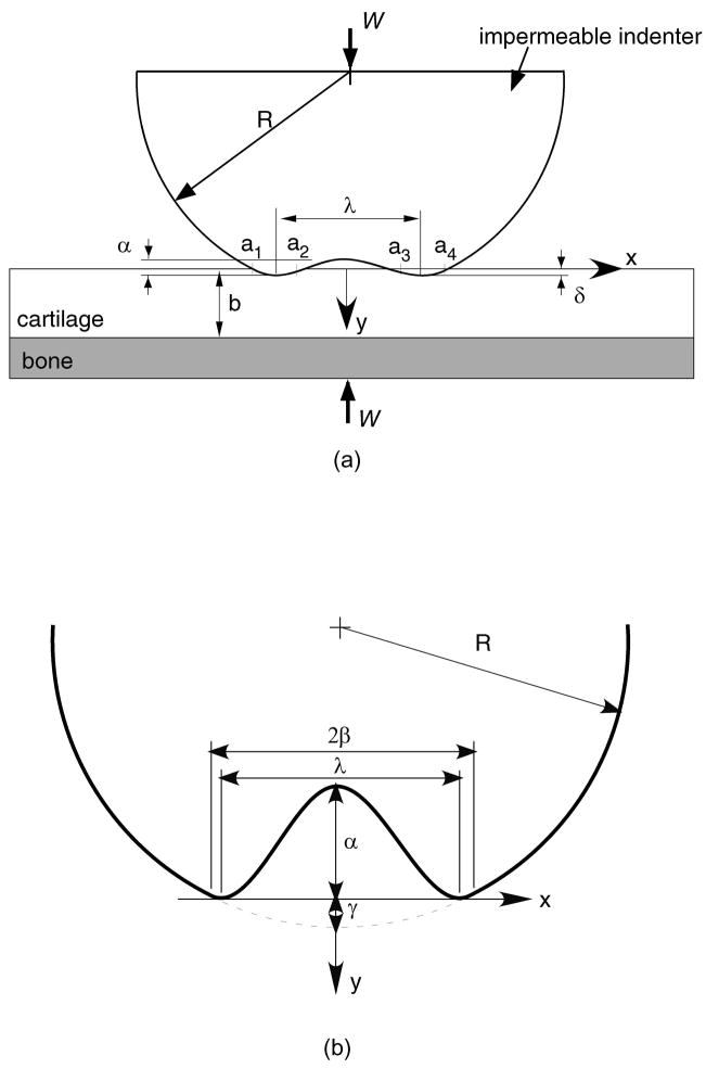
The contact configuration for the problems analyzed in this study is presented in Figure 1a. A biphasic cartilage layer of uniform thickness b is supported by a rigid impermeable subchondral bone substrate. A rigid impermeable indenter contacts the biphasic layer under an applied load intensity W (load per unit length along the out-of-plane or z–direction). The profile g(x) of the indenter is a parabolic approximation to a cylinder of radius R, with a centrally located sinusoidal ripple of peak-to-peak amplitude α and wavelength λ:
| (1) |
where β is the abscissa where the parabola and sinusoid are C1 -continuous (Figure 1b), which can be obtained from απRsin(2πβ/λ) + λβ = 0, and γ = (β2/2R) − (α/2)[1 + cos(2πβ/λ)]. In the creep contact analysis, the load W is applied at time t = 0 and maintained constant, with the bony substrate remaining stationary.
Figure 1.
(a) Geometry of the contact configuration for an impermeable indenter on a biphasic surface. (b) The region at the center of contact contains the trapped lubricant
Tissue and Lubricant Models
The governing equations for the biphasic theory of Mow et al. [10], include the balance of mass for the mixture,
| (2) |
and the balance of linear momentum for each phase,
| (3) |
where s, f denote the solid and fluid phases, respectively. In these equations, ϕα is the volumetric fraction, ρα is the apparent density, vα is the velocity, bα is the external body force per unit mass, and πα is the momentum exchange, for phase α. The constitutive relations for a linear elastic solid phase and a Newtonian fluid phase are
| (4) |
| (5) |
| (6) |
where σα is the apparent stress for phase α, p is the interstitial fluid pressure, λs, μs are the first and second Lamé constants of the solid phase, λf, μf are the first and second viscosity coefficients of the fluid phase, and k is the hydraulic permeability of the porous-permeable solid matrix. The total stress is given by
| (7) |
where σe is the effective stress. The infinitesimal strain tensor E of the solid matrix is related to the solid displacement u through E = (gradu + gradT u)/2, and the rate of deformation tensor D f of the fluid phase is given by D f = (grad v f + gradT vf)/2. The solid phase velocity vs is related to the solid phase displacement u by the material derivative with respect to the solid phase vs = Dsu Dt. Substitution of these constitutive relations into the balance of linear momentum equations, in the absence of external body forces, and neglecting inertia forces, yields
| (8) |
| (9) |
It is convenient to define the flux of the fluid relative to the solid phase as
| (10) |
If equations (8)–(9) are non-dimensionalized with
| (11) |
where HA = λs + 2μs and b is a characteristic length (e.g., thickness) of the biphasic cartilage material, the following relations are produced,
| (12) |
| (13) |
For articular cartilage, ϕs,ϕf ~ 1, λs, μs, HA ~ 106 Pa, k ~ 10−15 m4/N.s, λf, μf, ~ 10−3 Pa.s, and b ~ 10−3 m, so that (λf + μf)k/b2, μfk/b2 ~ 10−12, from which it can be concluded that the term (λf + μf)grad(div vf) + μf∇2v f can be neglected in Eq.(9). Now, Eqs.(8)–(9) can be rearranged as
| (14) |
| (15) |
using ϕs + ϕf = 1; in effect, these equations correspond to λf = μf = 0. These two equations, along with Eq.(2) which can be rewritten as div(vs + w) = 0, can be used to solve for the dependent variables u, w, and p, subject to the appropriate boundary conditions.
Modeling the trapped lubricant pool as an incompressible Newtonian fluid similarly produces the governing equations
| (16) |
| (17) |
where v is the lubricant velocity, p its pressure and η its viscosity. In a two-dimensional analysis,
| (18) |
From the boundary conditions, the lubricant at the top surface of the trapped lubricant pool moves at the velocity of the rigid indenter, while at the bottom cartilage surface the lubricant moves at the mixture velocity (Figure 1a),
| (19) |
For simplicity, it is now assumed that since the lubricant pool has a small height, the velocity component vy (x,y,t) of the lubricant can be reasonably estimated with a linear function of y that satisfies the above conditions,
| (20) |
From the continuity of mass equation, (18)1, we now get
| (21) |
Integrating this expression with respect to x and making use of the symmetry condition vx (0,y,t) = 0, it follows that ∂2vx/∂y 2 = 0. Then, from the momentum equation along x, (18)2,
| (22) |
In a biphasic creep problem, characteristic velocities of the solid phase and fluid flux are on the order of ∂uy/∂t ~ δ̇(t) ~ wy ~ HA k/b, which is approximately 10−6 m/s (~1 μm/s) for articular cartilage. Given that g(x) ~ 10−6 m and η ~10−3−100 Pa.s, while p ~ 105 Pa in the trapped lubricant pool, it is evident that the term multiplied by η in Eq.(22) is of order 100–103 Pa, which is entirely negligible compared to p. Thus the pressure is essentially uniform in the lubricant pool,
| (23) |
This order of magnitude analysis indicates that the effect of the lubricant viscosity is negligible in resisting the flow of lubricant into or out of the cartilage, when compared to the diffusive drag of the fluid phase against the solid matrix resulting from the low permeability of cartilage.
Contact Analysis
The methods of solution for the problem of this study follows the approach described in our earlier study of contact creep [4] in the absence of a trapped lubricant pool, and the reader is referred to that publication for a detailed description of the reduction of the above biphasic equations to the set of equations presented below. For the contact creep analysis, the convected term in the material derivative is negligible and thus Ds/Dt ≈ ∂/∂t. The contact analysis assumes frictionless conditions at the contact interface of the indenter with the biphasic layer, which is consistent with neglecting viscous terms in the interstitial fluid of the biphasic model. At the biphasic layer surface, the traction components are given as
| (24) |
where the complete determination of the functions pa and ta is to be obtained from the analysis. As can be construed from Figure 1, the following information about these functions is available a priori:
| (25) |
where ai (t) (i = 1,4) denote the edges of the contact regions and p0 is the value of the uniform pressure in the trapped pool. To solve for these functions within the contact regions (a1 ≤ x ≤ a2, a3 ≤ x ≤a4), it is first necessary to match the normal surface displacement of the biphasic layer with the profile g(x) of the rigid impermeable indenter and to set the normal fluid flux component to zero. For the contact creep problem, the components of solid displacement uy and fluid flux w y normal to the surface, expressed in terms of inverse complex Fourier transforms, are given by [4]
| (26) |
| (27) |
where p̃a (ω,t), t̃a (ω,t) are complex Fourier transforms of pa (x, t), ta (x, t), respectively. The known functions M̃p, M̃t, Ñp, Ñt are obtained by satisfying all the boundary conditions for the biphasic layer (adhesive and impermeable cartilage-bone interface, along with the traction boundary conditions of Eq.(24) above).
The continuity of normal surface displacement and fluid flux within the contact region is given by
For a1(t)≤ x ≤ a2(t), a3 (t) ≤ x ≤ a4(t)
| (28) |
| (29) |
where δ(t) is the normal approach of the indenter with the biphasic layer (Figure 1a). Because this normal approach is not known in advance, the system of equations to be solved must be supplemented with the following load balance equation (where W is assumed positive in compression)
| (30) |
Finally, it is necessary to satisfy the conservation of mass equation in the trapped lubricant pool. Given that the height of the pool is
| (31) |
the integral form of the conservation of mass equation is
| (32) |
where
| (33) |
is the volume of the trapped lubricant at the current time, and
is the volume of the trapped pool in the absence of surface deformation. It is assumed in this study that the initial volume of the trapped pool is V(0) = V0, though it should be understood that the initial condition may be chosen arbitrarily. The above equations are sufficient to solve for the unknown functions pa (x, t), ta (x, t), δ(t), p0 (t). The contact edges ai (t) (i = 1 to 4) are determined by satisfying the following conditions along the contact interface,
| (34) |
Solution Scheme
A computational domain −L ≤ x ≤ L which includes the contact region is discretized into n uniform mesh intervals of length Δx. A collocation method is employed to solve for the unknown tractions pa (x, t), ta (x, t) at every mesh point xj that falls within the contact region (a1 ≤ xj ≤ a2, a3 ≤ xj ≤ a4, j = 1 to m), including the lubricant pool pressure p0 (t). The surface tractions are represented by the interpolation functions
| (35) |
with unknown coefficients p0 (t), ξk (t), ηk (t), where the basis functions bk (x) are of the form
| (36) |
Fast Fourier Transforms (FFT) can be used to transform these known basis functions to produce general expressions for p̃a (ω,t) and t̃a (ω,t) from Eq. (35), which can be substituted into Eqs. (26)–(27); an inverse FFT can be performed in turn on these resulting equations to provide general expressions for the surface displacement and fluid flux of the form
| (37) |
where the basis functions ck (x, t), dk (x, t), ek (x, t), fx (x, t) are known,
| (38) |
To solve for all the unknowns, Eq.(37) is substituted into Eqs.(28)–(29) to produce 2m equations (two for each x j within the contact regions):
For a1 ≤ xj ≤ a2, a3 ≤ xj ≤ a4,
| (39) |
| (40) |
Equation (35) gets substituted into a discretized Eq.(30) using the trapezoidal rule of integration, and simplified using Eqs.(34) & (36),
| (41) |
Using a backward difference scheme for the time derivative, the discretized form of Eq.(32), using Eqs.(33)&(37), becomes
| (42) |
Initial guesses are provided for the contact edges ai (t) and an iterative scheme is used whereby the 2m + 2 equations in Eqs.(39)–(42) are solved linearly for the unknown functions ξ (t), ηk (t), p0 (t), δ(t) (k = 1 to m) at each time step. Iterative refinements are performed until Eq.(34) is satisfied within a given tolerance at the current time step. In summary, there are two nested loops in this numerical scheme: 1) the iterative loop on ai (t); and 2) the time incrementation loop. For numerical efficiency, advantage is taken of the problem symmetry about x = 0.
Friction Coefficient Prediction
Cartilage being a porous-permeable solid matrix saturated with fluid, in our biphasic boundary friction model proposed earlier [13] the friction force (Wτ) developed during boundary contact of two biphasic bearing surfaces is assumed to result primarily from solid-to-solid interactions at the contact interface. In its simplest embodiment analogous to Amonton’s law, this model assumes that the friction force is only proportional to the portion of the total normal force transmitted by solid-to-solid contact, given by
| (43) |
where φs0,φs1 represent the solid area (and volume) fractions of the opposing bearing surfaces, respectively (alternatively, 1 − φs = fluid area fraction or porosity). In this expression, Wb is the total normal load transmitted across the contact interface where boundary biphasic contact occurs and is the resultant of the interstitial fluid pressure over the same contact region (all taken positive in compression). For the current problem, these are given by
| (44) |
The physical interpretation of Eq.(43) follows from the recognition that the interstitial fluid pressure at the contact interface, pa (x,t), supports load across the interface wherever fluid interacts with fluid or with solid, i.e., over the contact area fraction (1 − φs0φs1); thus, the actual normal load supported by the fluid is , and the remainder from the total load is the normal load supported by solid-to-solid contact. (Note that these expressions properly reduces to expected limits as either of φs0,φs1 reduces to zero in the limit of a pure fluid, or unity in the limit of a pure solid.) Neglecting the friction resulting from viscous effects in the fluid (i.e., fluid-fluid and fluid-solid interactions), the friction force can be modeled in its simplest form as
| (45) |
where μ eq is the equilibrium friction coefficient (after the interstitial fluid pressure has subsided within the tissue). However, in the presence of a trapped lubricant pool, boundary contact occurs only over the ranges a1≤ x ≤ a2 and a3 ≤ x≤ a4, yet the pressurized lubricant contributes to the total load supported across the interface by an amount
| (46) |
while frictional effects in the range a2 < x< a3 are also considered negligible. Hence the effective friction coefficient across the entire contact interface is given by
| (47) |
This equation differs from our previously proposed model by the addition of the load to the denominator, representing the contribution from the trapped lubricant pool. Everything else being equal, this equation confirms the expectation that pressurization of a trapped lubricant will help further reduce the friction coefficient, above and beyond the biphasic effect where interstitial fluid pressurization supports load across the boundary contact interface.
Model Parameters
Representative material constants for the cartilage layer are taken to be μs = 0.25 MPa, λ = 0 MPa, and k = 2×10⁻¹⁵ m4/N.s; a typical layer thickness of b = 1 mm is assumed [35]. Typical values for the radius of the indenter are taken to be R = 0.1, 0.2, and 1.0 m, and for the load intensity, W = 0.25, 0.5, and 1.0 kN/m. To investigate the effect of the initial size of the trapped lubricant pool, the height and width of the ripple are varied in the range α = 1 to 5 μm and λ = 0.1 to 1 mm, respectively. The typical domain for the numerical analysis is taken to be 2L = 8(a4 − a1), with the number of mesh intervals n = 2048 or 4096 (a power of 2 for the FFT analysis). For the contact creep analysis, 50 logarithmic increments in time are employed ranging from 10 ms to 10,000 s.
For the friction simulations, the solid area fraction of the impermeable indenter is unity while that of the cartilage layer is assumed to be 0.20 (i.e., 80% water content, thus φs0φs1 = 0.20); the equilibrium friction coefficient, μ eq, is taken to be 0.30 [8,11].
RESULTS
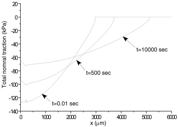
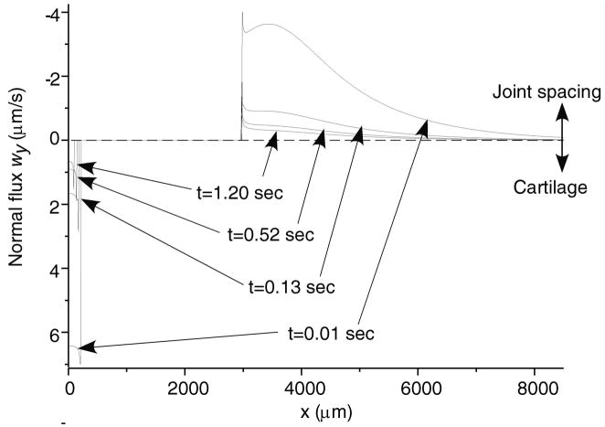
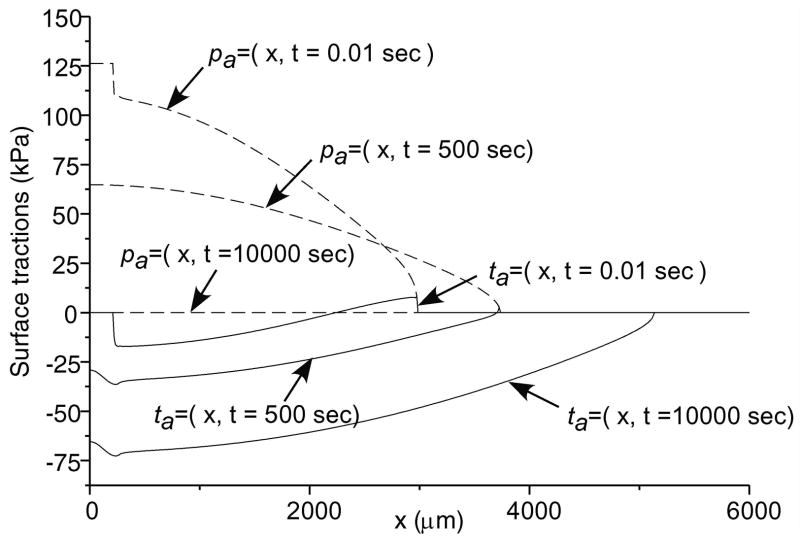
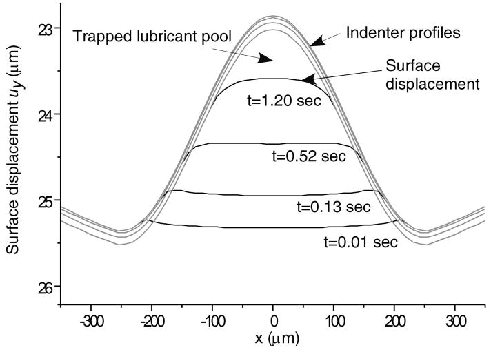
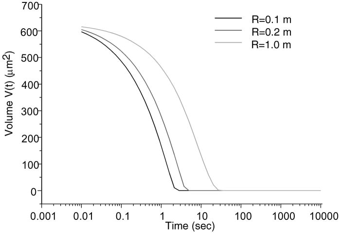
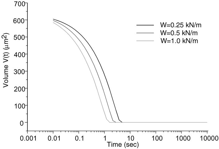
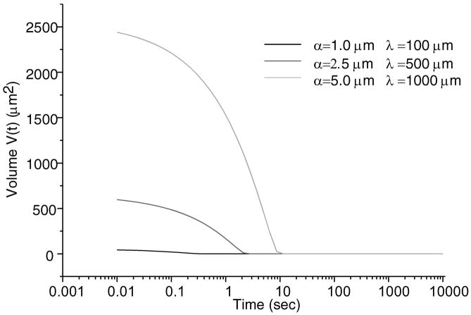
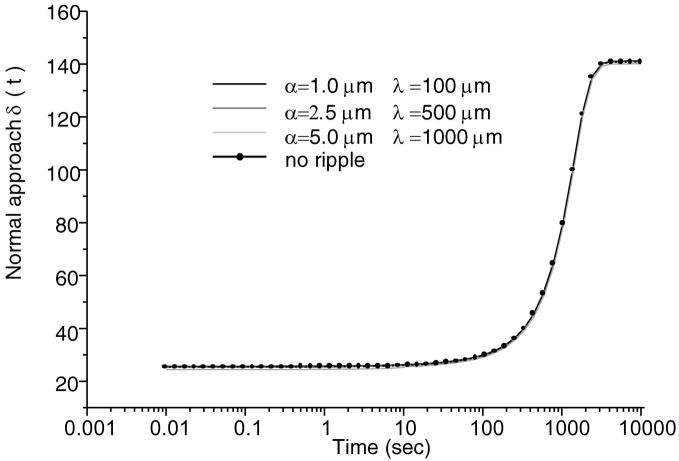
Total normal surface traction, − pa (x,t) + ta (x, t), is presented in Figure 2 for the early time (t = 0.01 sec.), and intermediate time when the volume of lubricant has depleted (t = 500 sec.) and the near equilibrium time (t = 10,000 sec.) when the fluid pressure is essentially zero (input parameters for this case are: W = 0.5 kN/m, R = 0.1 m, α = 2.5 μm, λ = 0.5 mm); as expected, in the region of the trapped lubricant, the total traction is homogeneous and equal in magnitude to the lubricant pressure p0 (t). A plot of the normal fluid flux (Figure 3) shows that the lubricant always flows out of the pool into the biphasic layer in the range a2 (t) < x< a3 (t), while interstitial fluid flows out of the cartilage layer outside of the contact region (x< a1 (t), x> a4 (t)); the equilibrium response of the contact creep problem is achieved when the fluid flux and interstitial fluid pressure reduce to zero. The individual components pa (x, t) and t a (x, t) of the surface traction are displayed at selected time points in Figure 4; as long as the lubricant pool is sustained, the elastic traction and fluid pressure exhibit relatively large gradients as x → a2 and a3 ← x. A close-up of the surface normal displacement profile near the ripple is shown for select time points in Figure 5; over time, the width of the lubricant pool decreases as fluid flows into the cartilage. The volume V(t) of the lubricant pool decreases with time until the pool collapses, as demonstrated in Figure 6 for various radii of curvature R, Figure 7 for various load intensities W, and Figure 8 for various choices of the ripple dimensions α and λ. Given the same ripple dimensions and applied load, increasing the indenter radius of curvature increased the sustainability of the lubricant pool from t = 2.8 s for R = 0.1 m to t = 35.6 s for R = 1 m; conversely, for given ripple dimensions and indenter radius of curvature, increasing the load produced shorter times to lubricant pool collapse, from t = 4.9 s at W = 0.25 kN/m to t = 1.6 s for W = 1.0 kN/m; as might be expected, larger ripples required longer times to lubricant depletion, from t = 0.4 s for the smallest ripple (α = 1 μm, λ = 0.1 mm) to t = 115 s for the largest (α = 5 μm, λ = 1 mm). The time response of the normal approach δ(t) for various ripple dimensions is shown in Figure 9; no noticeable differences can be observed in this variable for various ripple dimensions.
Figure 2.
Total normal contact traction (a) for early time response (t = 0.01 sec) (b) an intermediate time when the pool of lubricant has collapsed (t = 500 sec), and (c) near equilibrium response (t = 10000 sec). For this case W = 0.5kN/m, R = 0.1 m, α = 2.5μm and λ = 500μm.
Figure 3.
Normal fluid flux across the surface of the tissue. In the fluid pocket the flow is into the tissue. At the periphery of the contact area the flow is into the joint spacing for the above geometry. (Same parameters as in Figure 2.)
Figure 4.
Interfacial fluid pressure, pa, and normal effective traction, ta, at several time points for the above geometry. (Same parameters as in Figure 2.)
Figure 5.
Surface displacement for selected early times inside the ripple region for the above geometry.
Figure 6.
Trapped lubricant volume changes over time various radii. W = 0.5kN/m, α = 2.5μm and λ = 500μm.
Figure 7.
Trapped lubricant volume changes over time for various applied loads. R = 0.1 m, α = 2.5μm and λ = 500μm.
Figure 8.
Trapped lubricant volume changes over time for various parameters α and λ, with W = 0.5kN/m and R = 0.1m.
Figure 9.
Variation of the normal approach between surfaces with time. W = 0.5kN/m and R = 0.1 m.
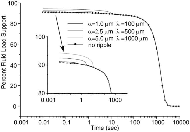
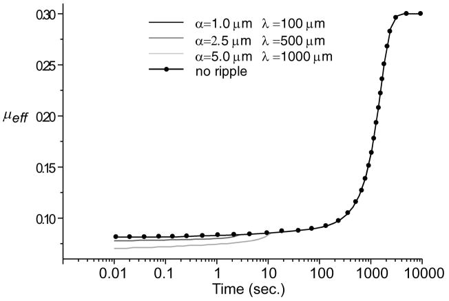
The total fluid load support for various ripple configurations is shown in Figure 10. Increasing the dimensions of the ripple region increased the fluid load support. Combining this result with predictions of the solid-to-solid load over the biphasic region, the effective friction coefficient μeff is calculated from Eq.(47) and shown in Figure 11. Greater fluid load support and reduced solid-to-solid load as found with the larger ripple (α = 5 μm, λ = 1 mm) decreased the minimum effective friction coefficient for longer durations than with the smaller ripples.
Figure 10.
Time-dependent fluid support, W p/W (×100%), for various ripple dimensions and for no ripple. W = 0.5kN/m, R = 0.1m.
Figure 11.
Simulated effective friction coefficient, μeff, for various ripple dimensions and for no ripple. W = 0.5kN/m, R = 0.1m.
DISCUSSION
The objective of this study was to investigate what would happen to a pool of lubricant trapped at the contact interface of a rippled indenter with a biphasic cartilage layer. This investigation falls within a broader effort to understand the mechanism of lubrication in diarthrodial joints. It had long been observed that the frictional response of articular cartilage is time-dependent, with the friction coefficient achieving very small values (e.g., ~0.001–0.08) in the early time response under the action of a constant load, but eventually reaching a considerably larger value (e.g., ~0.15–0.42) over several thousand seconds of loading [7,8,9,11,19 36,37]. McCutchen [7,8] postulated that this time-dependent response should be attributed to the transient pressurization of the interstitial water of cartilage, and our recent study [13] formulated this concept within the context of the biphasic theory for cartilage [10], as embodied in Eq.(47) with . Contrary to the weeping hypothesis however, the current analysis demonstrates that lubricant fluid trapped between a rigid impermeable surface and a porous-permeable cartilage layer flows monotonically into the cartilage during contact creep; no fluid flow from the cartilage into the lubricant pool is observed. Combined with the squeeze-film lubrication analyses of earlier studies [28–32], which investigated the pattern of fluid flow prior to contact between the surfaces, this result is in better agreement with the premise of the boosted lubrication theory of Walker et al. [16]. Nevertheless, the lubricant flow direction does not affect the fundamental role of interstitial fluid pressurization in reducing friction at the contact interface.
For the analyzed ripple size most representative of the smallest scale of cartilage surface roughness (α = 1 μm, λ = 0.1 mm), the current study demonstrates that the lubricant pool gets depleted in 0.4 s only. This result suggests that the smallest asperities of the articular surface do not play a significant beneficial role in trapping lubricant and in enhancing lubrication. However, according to some earlier literature studies, cartilage exhibits different levels of topographical variations between the primary anatomic contours and the smallest surface asperities [15], some of which may correspond more closely to the upper range of ripple parameters employed in this study (α = 5 μm, λ = 1 mm), in which case the time to lubricant depletion is in excess of two minutes. These higher durations suggest that under physiological loading conditions when intermittent loads are applied over periods of a few seconds, the lubricant pools may remain viable. More recent studies of the measurement of articular surface structure using stylus and laser profilometry, confocal microscopy and atomic force microscopy [19,20,21] have supported earlier reports of articular surface roughness. In particular, using laser profilometry, Forster and Fisher [19] measured a cartilage surface roughness of Ra = 0.8 μm over a 800×800 μm region in one specimen; using conventional stylus profilometry over a length of 800 μm, the surface roughness (Ra) over eight specimens averaged 1.6±0.9 μm, while the mean of maximum peak-to-valley heights (Rtm) was 5.6±2.6 μm. While the AFM study of Jurvelin et al. [18], performed over regions of 80×80 μm or less, discounted the existence of surface structures detected in the earlier SEM literature, our own recent AFM study of immature bovine cartilage has confirmed the existence of surface asperities ranging from 2 to 6 μm, with an average surface roughness of Ra = 0.6 μm over a 100×100 μm region [21]. Therefore, these recent studies support the earlier literature on the existence of articular surface structures over larger scales, which may help trap lubricant pools.
For the smallest ripple dimensions, it is interesting that the time for lubricant depletion is of the same order of magnitude as the squeeze-film time in the lubrication analysis of Hlavacek [31] where the synovial fluid turns into a gel upon sufficient ultrafiltration of its low molecular weight solvent, both analyses dealing with the flow of lubricant into cartilage. Hlavacek [30–32,38] has found that the fluid flux normal to the articular surface varies as wy ~ t−1/2, and a curvefit of the fluid flux response at the center of the trapped lubricant pool in the current study (Figure 3) finds a dependence of wy ~ t−0.47, confirming Hlavacek’s earlier finding. In contrast, the analyses of Hou et al. [28] and Jin et al. [29] predict a slower rate of fluid flow across the cartilage surface, which Hlavacek attributes to their omission of the jump in fluid pressure upon instantaneous loading [38].
Having established that the lubricant pool is transient, it becomes of interest to determine to what extent it may contribute to decreasing the effective friction coefficient, even if for a short period of time. In recent friction experiments of bovine articular cartilage cylindrical plugs against glass, subjected to creep loading [37], it has been observed that the minimum value μmin of the effective friction coefficient μeff averages μmin = 0.02 (with a range of 0.001–0.08) while the equilibrium friction coefficient averages μeq = 0.21 (with a range of 0.15–0.42). According to Eq.(47), in the absence of a trapped lubricant pool ( ), it follows that for these mean values,
| (48) |
In this expression it is recognized that the minimum value of the effective friction coefficient is achieved when the fluid load support is at its maximum (immediately upon loading, for a creep analysis, as evident from Figure 10, or from experimental studies [5,6]). It becomes apparent that for glass against cartilage (φs0φs1 ~ 0.2), unlike the case of cartilage-against-cartilage (φs0φs1 ~ 0.04), it is not possible to satisfy Eq.(48) for any value of the fluid load support since . This finding thus motivates the analysis of the effect of a trapped lubricant pool based on the following argument. When two bearing surfaces approach each other upon loading, it is possible to separate the response into three phases: (1) A squeeze film response where there is no contact occurring between the bearing surfaces [28–32]; this case is idealized in the current friction model by the limiting conditions φs0φs1→ 0, , and μmin, μeff → 0. (2) A mixed lubrication regime where contact occurs at micro-asperities, trapping lubricant in pools; this case is modeled by Eq.(47) with . (3) A boundary lubrication regime where trapped lubricant pools have been depleted, but where a transient response in the friction coefficient is still observed, modeled by Eq.(47) with . It is surmised here that the experimental measurements of μmin typically occur some time during the mixed lubrication phase of this response. As can be observed from the results in Figure 11, even the idealized case of a single ripple reduces the theoretically predicted value of the minimum friction coefficient and works toward eliminating the apparent inconsistency between theory and experiments resulting from Eq.(48) for the case of cartilage-against-glass. If multiple ripples were to be modeled, as would be straightforward by following the above methodology, it is expected that even greater agreement between theory and experiments would occur. Consequently, it is likely that trapped lubricant pools play an essential role in helping to reduce the frictional coefficient and wear under physiological loading conditions, particularly in the early time response.
The problem addressed in this study offers several levels of modeling and numerical complexity, which have necessitated various simplifying assumptions. Based on order of magnitude analyses, the contribution of lubricant viscosity was neglected in this problem. Cartilage was modeled with the linear biphasic theory using an isotropic constitutive relation for the solid matrix under small strains, with homogeneous material properties; experimental studies suggest that cartilage behaves nonlinearly and anisotropically, and that its properties are inhomogeneous through the depth. Thus, future studies may need to model these properties. Because of the limitation of small strain theory, the load magnitudes applied in the current analysis were sub-physiological; however increasing loads produced more rapid lubricant depletion (Figure 7) and it is likely that a finite deformation analysis that could model more realistic load magnitudes would confirm this trend. It was also assumed that the dominant mechanism of friction in cartilage results from solid rubbing against solid, with the viscosity of the lubricant contributing a negligible amount of frictional force [11,13,39]. Finally, boundary lubrication mechanisms were not directly modeled or explored in the current analysis [40,41], though they are subsumed in the equilibrium coefficient μeq in Eq.(47) [12,13].
In summary, this study offers a solution for the creep contact response between a rigid impermeable indenter and a biphasic layer, with a trapped lubricant pool, which can help explain the mechanism of lubrication of articular cartilage. In our earlier formulation of a boundary friction model at the interface of solid-fluid mixtures, lubricant trapping was not taken into account [13]. The current study represents a generalization of that model which has interesting ramifications. First, it allows modeling of lubricant trapping due to surface features, such as roughness or waviness, that produce an enclosure upon contact with another surface, and which can potentially explain the very low friction coefficient of cartilage observed upon loading. Second, it provides a formulation for the friction coefficient that can account for the transition from a mixed lubrication regime to a boundary lubrication regime, while still accommodating the porous nature of the bearing surfaces. We conclude that the results presented in this study support the hypothesis that trapped lubricant decreases the effective area of contact between contacting surfaces while simultaneously enhancing the fluid load support, thereby decreasing the initial friction coefficient following load application, independently of squeeze-film lubrication effects.
Acknowledgments
This study was supported by a grant from the National Institutes of Health (AR43628).
References
- 1.Ateshian GA, Lai WM, Zhu WB, Mow VC. An asymptotic solution for two contacting biphasic cartilage layer. J Biomech. 1994;27:1347–1360. doi: 10.1016/0021-9290(94)90044-2. [DOI] [PubMed] [Google Scholar]
- 2.Macirowski T, Tepic S, Mann RW. Cartilage stresses in the human hip joint. J Biomech Eng ASME. 1994;116:11–18. doi: 10.1115/1.2895693. [DOI] [PubMed] [Google Scholar]
- 3.Ateshian GA, Wang H. A theoretical solution for the rolling contact of frictionless cylindrical biphasic articular cartilage layers. J Biomech. 1995;28:1341–1355. doi: 10.1016/0021-9290(95)00008-6. [DOI] [PubMed] [Google Scholar]
- 4.Kelkar R, Ateshian GA. Contact creep of biphasic cartilage layers: Identical layers. J App Mech ASME. 1999;66:137–145. [Google Scholar]
- 5.Soltz MA, Ateshian GA. Experimental verification and theoretical prediction of cartilage interstitial fluid pressurization at an impermeable contact interface in confined compression. J Biomechanics. 1998;31:927–934. doi: 10.1016/s0021-9290(98)00105-5. [DOI] [PubMed] [Google Scholar]
- 6.Soltz MA, Ateshian GA. Interstitial fluid pressurization during confined compression cyclical loading of articular cartilage. Ann Biomed Eng. 2000;28:150–159. doi: 10.1114/1.239. [DOI] [PubMed] [Google Scholar]
- 7.McCutchen CW. Sponge-hydrostatic and weeping bearing. Nature. 1959;184:1284. doi: 10.1038/1841284a0. [DOI] [PubMed] [Google Scholar]
- 8.McCutchen CW. The frictional properties of animal joints. Wear. 1962;5:1–17. [Google Scholar]
- 9.Malcom LL. Ph.D. Thesis. University of California; San Diego: 1976. An Experimental investigation of the frictional and deformational responses of articular cartilage interfaces to static and dynamic loading. [Google Scholar]
- 10.Mow VC, Kuei SC, Lai WM, Armstrong CG. Biphasic creep and stress relaxation of articular cartilage in compression: Theory and experiments. J Biomech Eng ASME. 1980;102:73–84. doi: 10.1115/1.3138202. [DOI] [PubMed] [Google Scholar]
- 11.Forster H, Fisher J. The influence of loading time and lubricant on the friction of articular cartilage. Proc Instn Mech Engrs. 1996;210(Part H):109–119. doi: 10.1243/PIME_PROC_1996_210_399_02. [DOI] [PubMed] [Google Scholar]
- 12.Ateshian GA. A theoretical formulation for boundary friction in articular cartilage. J Biomech Eng ASME. 1997;119:81–86. doi: 10.1115/1.2796069. [DOI] [PubMed] [Google Scholar]
- 13.Ateshian GA, Wang H, Lai WM. The role of interstitial fluid pressurization and surface porosities on the boundary friction of articular cartilage. J Tribology ASME. 1998;120:241–251. [Google Scholar]
- 14.Gardner DL. The influence of microscopic technology on knowledge of cartilage surface structure. Ann Rheum Dis. 1972;31:235–258. doi: 10.1136/ard.31.4.235. [DOI] [PMC free article] [PubMed] [Google Scholar]
- 15.Longmore RB, Gardner MJ. Development with age of human articular cartilage surface structure. Ann Rheum Dis. 1975;34:26–37. doi: 10.1136/ard.34.1.26. [DOI] [PMC free article] [PubMed] [Google Scholar]
- 16.Walker PS, Dowson D, Longfield MD, Wright V. Boosted lubrication” in synovial joints by fluid entrapment and enrichment. Ann Rheum Dis. 1968;27:512–520. doi: 10.1136/ard.27.6.512. [DOI] [PMC free article] [PubMed] [Google Scholar]
- 17.Clarke IC. Articular cartilage: A review and scanning electron microscope study. J Bone J Surg. 1971;53b:67–71. [PubMed] [Google Scholar]
- 18.Jurvelin JS, Muller DJ, Wong M, Studer D, Engel A, Hunzoker EB. Surface and subsurface morphology of bovine humeral articular cartilage as assessed by atomic force and transmission electron microscopy. J Structural Biology. 1996;117:45–54. doi: 10.1006/jsbi.1996.0068. [DOI] [PubMed] [Google Scholar]
- 19.Forster H, Fisher J. The influence of continuous sliding and subsequent surface wear on the friction of articular cartilage. Proc Instn Mech Engrs. 1999;213(Part H):329–345. doi: 10.1243/0954411991535167. [DOI] [PubMed] [Google Scholar]
- 20.Gardner DL, Salter DM, Oates K. Advances in the Microscopy of Osteoarthritis. Microsc Res Tech. 1997;37:245–270. doi: 10.1002/(SICI)1097-0029(19970515)37:4<245::AID-JEMT2>3.0.CO;2-K. [DOI] [PubMed] [Google Scholar]
- 21.Moa-Anderson BJ, Costa KD, Hung CT, Ateshian GA. Bovine articular cartilage surface topography and roughness in fresh versus frozen tissue samples using atomic force microscopy. Proceeding of the 2003 Summer Bioengineering Conference; 2003. in review. [Google Scholar]
- 22.Walker PS, Unsworth A, Dowson D, Sikorski J, Wright V. Mode of aggregation of hyaluronic acid protein complex on the surface of articular cartilage. Ann Rheum Dis. 1970;29:591–602. doi: 10.1136/ard.29.6.591. [DOI] [PMC free article] [PubMed] [Google Scholar]
- 23.Dowson D, Unsworth A, Wright V. Analysis of ‘boosted lubrication’ in human joints. J Mech Eng Sci. 1970;12:364–369. [Google Scholar]
- 24.Longfield MD, Dowson D, Walker PS, Wright V. Boosted lubrication” of human joints by fluid enrichment and entrapment. Biomed Eng. 1969;4:517–522. [PubMed] [Google Scholar]
- 25.Maroudas A. Hyaluronic acid films. Proc IMechE. 1967;181:122–124. [Google Scholar]
- 26.Dowson D, Jin ZM. A full numerical solution to the problem of microelastohydrodynamic lubrication of a stationary compliant wavy layered surface firmly bonded to a rigid substrate with particular reference to human synovial joints. Proc Instn Mech Engrs. 1992;206(Part H):185–193. doi: 10.1243/PIME_PROC_1992_206_290_02. [DOI] [PubMed] [Google Scholar]
- 27.Hou JS, Holmes MH, Lai WM, Mow VC. Boundary conditions at the cartilage-synovial fluid interface for joint lubrication and theoretical verifications. J Biomech Eng. 1989;111:78–87. doi: 10.1115/1.3168343. [DOI] [PubMed] [Google Scholar]
- 28.Hou JS, Mow VC, Lai WM, Holmes MH. Squeeze film lubrication for articular cartilage with synovial fluid. J Biomech. 1992;25:247–259. doi: 10.1016/0021-9290(92)90024-u. [DOI] [PubMed] [Google Scholar]
- 29.Jin ZM, Dowson D, Fisher J. The effect of porosity of articular cartilage on the lubrication of a normal human hip joint. Proc Inst Mech Eng [H] 1992;206:117–124. doi: 10.1243/PIME_PROC_1992_206_279_02. [DOI] [PubMed] [Google Scholar]
- 30.Hlavácek M. The role of synovial fluid filtration by cartilage in lubrication of synovial joints II. Squeeze-film lubrication: homogeneous filtration. J Biomech. 1993;26:1151–1160. doi: 10.1016/0021-9290(93)90063-k. [DOI] [PubMed] [Google Scholar]
- 31.Hlavácek M. Squeeze film lubrication of the human ankle joint with synovial fluid filtrated by articular cartilage with the superficial zone worn out. J Biomech. 2000;33:1415–1422. doi: 10.1016/s0021-9290(00)00109-3. [DOI] [PubMed] [Google Scholar]
- 32.Hlavácek M. The influence of the acetabular labrum seal, intact articular superficial zone and synovial fluid thixotropy on squeeze-film, lubrication of a spherical synovial joint. J Biomech. 2002;35:1325–1335. doi: 10.1016/s0021-9290(02)00172-0. [DOI] [PubMed] [Google Scholar]
- 33.Kuznetsov YA. Effects of fluid lubricant on the contact characteristics of rough elastic bodies in compression. Wear. 1985;102:177–194. [Google Scholar]
- 34.Avitzur B. Effect of surface irregularities, substrate surface layers, pressure, lubrication and sliding speed on friction resistance to sliding metals. Key Eng Material. 1989;33:1–16. [Google Scholar]
- 35.Athanasiou KA, Rosenwasser MP, Buckwalter JA, Malinin TI, Mow VC. Interspecies comparison of in situ intrinsic mechanical properties of distal femoral cartilage. J Orthop Res. 1991;9:330–340. doi: 10.1002/jor.1100090304. [DOI] [PubMed] [Google Scholar]
- 36.Soltz MA, Mauck RL, Hung CT, Ateshian GA. Osmotic pressure influence on the frictional response of articular cartilage. Trans Orthop Res Soc. 2001;26:60. [Google Scholar]
- 37.Ateshian GA, Soltz MA, Mauck RL, Hung CT, Lai WM. The role of osmotic pressure in the frictional response of articular cartilage. Transport in Porous Media. In Press. [Google Scholar]
- 38.Hlavacek M. Lubrication of the human ankle joint in walking with the synovial fluid filtrated by the cartilage with the surface zone worn out: steady pure sliding motion. J Biomech. 1999;32:1059–1069. doi: 10.1016/s0021-9290(99)00095-0. [DOI] [PubMed] [Google Scholar]
- 39.Ateshian GA, Wang X. Boundary Conditions at the Viscous Sliding Interface of Incompressible Porous Deformable Media. In: Sändig A-M, Schiehlen W, Wendland W, editors. Multifield Problems, State of the Art. Springer Verlag; Berlin: 2000. pp. 115–124. [Google Scholar]
- 40.Swann DA, Silver FH, Slayter HS, Stafford W, Showe E. The molecular structure and lubricating activity of lubricin from bovine and human synovial fluids. Biochem J. 1985;225:195–201. doi: 10.1042/bj2250195. [DOI] [PMC free article] [PubMed] [Google Scholar]
- 41.Hills BA. Boundary lubrication in vivo. Proc Instn Mech Engrs. 2000;214(Part H):83–94. doi: 10.1243/0954411001535264. [DOI] [PubMed] [Google Scholar]


