

Abstract
Importance of the field
Microneedles are small-scale devices that are finding use for transdermal delivery of protein-based pharmacologic agents and nucleic acid-based pharmacologic agents; however, microneedles prepared using conventional microelectronics-based technologies have several shortcomings, which have limited translation of these devices into widespread clinical use.
Areas covered in this review
Two photon polymerization is a laser-based rapid prototyping technique that has been recently used for direct fabrication of hollow microneedles with a wide variety of geometries. In addition, an indirect rapid prototyping method that involves two photon polymerization and polydimethyl siloxane micromolding has been used for fabrication of solid microneedles with exceptional mechanical properties.
What the reader will gain
In this review, the use of two photon polymerization for fabricating in-plane and out-of-plane hollow microneedle arrays is described. The use of two photon polymerization-micromolding for fabrication of solid microneedles is also reviewed. In addition, fabrication of microneedles with antimicrobial properties is discussed; antimicrobial microneedles may reduce the risk of infection associated with formation of channels through the stratum corneum.
Take home message
It is anticipated that the use of two photon polymerization as well as two photon polymerization-micromolding for fabrication of microneedles and other microstructured drug delivery devices will increase over the coming years.
Keywords: rapid prototyping, two photon polymerization, drug delivery, transdermal, microneedle
1. Overview of the Market
Nucleic acid- and protein-based pharmacologic agents are finding greater use in the treatment of cancer, diabetes mellitus, and other chronic medical conditions. Oral, sublingual, or rectal delivery are the most appealing routes of administration due to the fact that doses can be administered by the patient. In addition, no painful or complicated techniques are necessary [1]. Unfortunately, many nucleic acid- and protein-based pharmacologic agents cannot be administered in enteral form due to pH driven molecular degradation or first-pass metabolism by the liver [2]. Transdermal patches have found increasing use in recent years for delivery of hormones (e.g., estrogen), analgesic agents (e.g., fentanyl), as well as various other pharmacologic agents; however, charged, polar, or large pharmacological agents cannot be delivered using transdermal patches because these agents cannot pass through an intact stratum corneum [3–5]. The stratum corneum is the outermost 15 µm thick layer of the epidermis, which contains nonviable keratinized cells and serves as a barrier to pharmacologic agent transport [6]. Transport of pharmacologic agents through the stratum corneum may be enhanced through the use of chemical penetration enhancers, electroporation, iontophoresis, and sonophoresis; however, these techniques have not seen widespread clinical use due to issues such as tissue irritation or limited effectiveness [1,7].
Nucleic acid- and protein-based agents are commonly delivered to subcutaneous tissues, muscle tissues, and veins by means of subcutaneous, intramuscular, and intravenous injections; these routes of administration avoid diffusion- and enzyme-related barriers. For example, insulin is a 51 amino acid residue, two-chain protein hormone that promotes glucose storage in the liver as well as in other body locations. Insulin cannot be orally delivered since it is either degraded by proteolytic enzymes in the gastrointestinal tract or metabolized in the liver. In addition, insulin also cannot be delivered using transdermal patches because it exhibits a relatively high molecular weight (5808 Da). Insulin is commonly delivered by means of subcutaneous injection [8, 9]. However, this route of administration is associated with trauma at the injection site as well as pain.
Microneedles are miniaturized lancet-, thorn-, or hypodermic needle-shaped devices that exhibit at least one dimension less than 500 µm; these devices may be used to create pores in the stratum corneum layer of the epidermis. By creating pores in the 15 µm thick stratum corneum layer, delivery of pharmacologic agents into deeper layers of the epidermis and the papillary dermis is enabled [10, 11]. Capillaries in the papillary dermis facilitate systemic absorption of pharmacologic agents. Pain to the patient may be minimized if microneedles do not interact with Meissner's corpuscles, Pacinian corpuscles, and nerve endings located within the dermis [12]. Trauma and tissue damage at the injection site are also minimized due to the small size of these devices; this property is especially appealing for patients with diabetes and other medical conditions who require frequent injections [13]. In addition, no specialized medical training or supervision is required for use of microneedles. Microneedles were shown to provide steady and rapid reductions in blood glucose levels in diabetic hairless rats; subcutaneous injection and microneedle delivery provided similar reductions in blood glucose levels [14].
Microneedle-based drug delivery mechanisms fall under three categories: (a) applying a microneedle to the skin in conjunction with another transdermal drug delivery technique (e.g., a transdermal patch); (b) coating a solid microneedle with a pharmacologic agent; and (c) infusing a liquid pharmacologic agent through the bore of a hollow microneedle. Pore formation and topical application have been performed to deliver a number of pharmacologic agents, including oligonucleotides, nucleic acids, and quantum dots [15–17]. Coated microneedles have been used for several classes of pharmacologic agents, including barium sulfate, bovine serum albumin, calcein, desmopressin, and plasmid deoxyribonucleic acid [18, 19]. In coated microneedle devices, the total amount of pharmacologic agent that can be delivered is determined by the surface area of the needle/patch assembly [20]. Since transport is controlled by diffusion, complex dosing (e.g., pulsatile dosing) is not possible. Microneedles with hollow bores may enable pressure-based delivery or diffusion-based delivery of pharmacologic agents to be maintained over an extended period of time. Devices containing microneedles and microfluidic pump systems may be used for controlled dosing of pharmacologic agents [5, 21–22, 23–24]. In addition, microneedles may be used for both drug delivery and fluid extraction by reversing the direction of fluid transport. For example, biosensors containing hollow microneedle patches may be used for blood sampling [21, 23]. These microneedle-based sensors are being considered for monitoring of chronic medical conditions that require frequent blood sampling, including monitoring of blood glucose levels in diabetes mellitus patients [6, 22]. Microneedles may be integrated with micropumps and biosensors to provide blood sampling as well as drug delivery for treatment of chronic disease. For example, patients with diabetes mellitus may be treated using transdermal "artificial pancreas" devices that provide continual blood glucose monitoring and insulin delivery; maintenance of blood glucose levels within the narrow euglycemic range would minimize ophthalmic, cardiovascular, nephrologic, and neurologic complications for these patients.
Microneedles have unique advantages for delivery of vaccines associated with high cost and limited availability, including vaccines for influenza viruses. Clinical studies by Belshe et al. and Kenney et al. have shown that intradermal administration of influenza vaccine enables use of reduced doses in comparison with conventional intramuscular administration [25, 26]. For example, Belshe et al. demonstrated that intradermal injection provides vigorous antibody responses with reduced doses for individuals between 18 years of age and 60 years of age; serum antibody responses for individuals who received intradermal injections (dose=6 µg of hemagglutinin for each antigen) and individuals who received intramuscular injections (dose=15 µg of hemagglutinin for each antigen) did not significantly differ [25]. Kenney et al. showed that intradermal administration of influenza vaccine (dose≥3 µg of hemagglutinin per strain) provided seroprotection and seroconversion rates that were similar to or better than those provided by intramuscular administration (dose≥15 µg of hemagglutinin per strain) [26]. The use of reduced doses, which is known as dose sparing, may enable the number of vaccine doses that are provided to a population using a given amount of vaccine to be maximized. Kim et al. attributed the improved immunogenic response provided by intradermal administration to antigen-presenting cell (e.g., dendritic cell) interactions with local lymph nodes [27].
Alarcon et al. demonstrated intradermal delivery administration of influenza vaccines using microneedles; several vaccines, including a whole inactivated influenza virus, a plasmid DNA encoding the influenza virus hemagglutinin, and a trivalent split-virion human vaccine, were examined using a rodent model [28]. They showed that microneedle delivery of the trivalent split-virion human vaccine for the H1N1 strain of the influenza virus provided at least ten-fold dose sparing compared with conventional intramuscular delivery. Zhu et al. examined solid metal microneedle arrays that were coated with inactivated influenza virus A using a rodent model [29]. They demonstrated that microneedle administration provided antibody responses similar to conventional intramuscular administration against influenza virus. Kim et al. evaluated delivery of trehalose-stabilized influenza vaccine using a microneedle patch in a rodent model [27]. They showed that microneedle vaccination was better than intramuscular vaccination for imparting protective immunity. In addition, the trehalose-stabilized microneedle vaccine elicited a stronger antibody response than the conventional unstabilized vaccine. Ding et al. demonstrated the use of cholera toxin and diphtheria toxoid as adjuvants for delivery of influenza subunit vaccine through microneedle array-treated skin in a rodent model. In a recent clinical study [30], Van Damme et al. carried out a prospective, randomized trial involving healthy adults to compare the immunogenicity of a low-dose intradermal influenza vaccine delivered by means of a microneedle device with that of a conventional intramuscular influenza vaccine delivered by means of a conventional hypodermic needle [31]. They showed that low-dose intradermal vaccination provided immunogenic responses similar to full-dose intramuscular vaccination.
Several investigators, including Bal et al., Haq et al., and Sivamani et al., have examined clinical use of microneedles [32–34]. Haq et al. compared the sensory response to skin penetration by 180 µm wet-etch silicon microneedles, 280 µm wet-etch silicon microneedles, and hypodermic needles [32]. Pain intensity was evaluated using a visual analogue scale, sensory perception was evaluated using an adapted McGill Pain Questionnaire, and skin penetration was evaluated using external staining as well as trans-epidermal water loss measurements. They showed that application of microneedles was associated with less pain than application of hypodermic needles. In addition, they demonstrated that resealing of channels created by microneedle penetration took place within 8–24 hours. Bal et al. examined transepidermal water loss, skin redness, blood flow, and pain sensation on ventral forearm skin after microneedle penetration [33]. A positive correlation between microneedle length and several parameters, including transepidermal water loss, skin redness, and blood flow, was observed. Microneedles were shown to disrupt the stratum corneum barrier layer with an absence of pain. Minimal skin irritation was noted after microneedle penetration; however, the duration of skin irritation did not exceed two hours. Sivamani et al. described the use of symmetric and pointed microneedle arrays for injection of methyl nicotinate into the volar forearm skin of human volunteers [34]. Microneedle penetration was associated with a pressure sensation; on the other hand, no pain was observed. They demonstrated that microneedle arrays were effective in enhancing methyl nicotinate delivery through the stratum corneum.
Over the past several decades, microneedles have been prepared using technologies that originated in the microelectronics and glassware industries. Many of these techniques have inherent limitations in terms of fabricating microneedles that exhibit large wall thicknesses as well as other fracture-resistant geometries. The concept of using miniaturized devices for transdermal drug delivery was originally developed approximately fifty years ago. In 1959, Wagner described the concept of using microneedle devices for transdermal drug delivery [35]. Methodologies for preparation of glass microneedles by hand pulling glass pipettes with a micropipette puller have been widely available for several decades (Figure 1c) [36–37]. These devices have been generally utilized in laboratory-based applications due to the fact that they exhibit poor fracture properties. In addition, preparation of glass microneedles by hand is an expensive, time-consuming process [37]. Approximately one decade ago, Prausnitz and colleagues began utilizing processes that originated in the microelectronics industry in order to fabricate microneedles for transdermal drug delivery [11]. For example, Henry et al. described fabrication of silicon microneedle arrays by mans of reactive ion etching. Since that time, silicon microneedles have been fabricated by Shikida et al., Wilke et al., Cromier et al., Griss et al., Roxhed et al., Gardeniers et al., Ji et al., and Stoeber et al. using microelectronics-based fabrication techniques such as wet etching, reactive ion etching, and deep reactive ion etching [18, 38–45]. Images of microneedles produced by etching of silicon are shown in Figure 1(a) and Figure 1(b). Wet etching is an isotropic process that involves selective chemical etching of silicon by means of a photo-patterned mask [38–40]. The geometries of microneedles prepared using etching processes are limited to radially symmetrical structures; a wide variety of simple geometric shapes such as pyramids, cones, and cylinders may be fabricated [41–45]. In addition, these techniques provide poor control over microneedle aspect ratio. Furthermore, reactive ion etching and deep reactive ion etching processes are line-of-sight methods that cannot create complex shapes, including overhanging structures [41–45].
Figure 1.
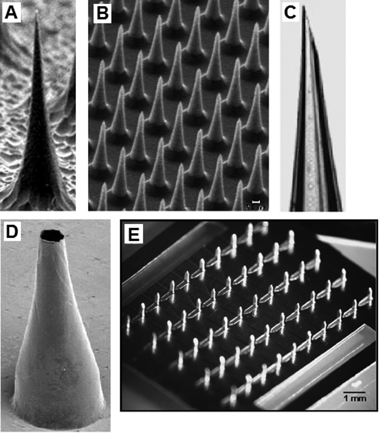
(a) Solid silicon microneedle fabricated by reactive ion etching. (b) Solid silicon microneedle array fabricated by reactive ion etching. (c) Hollow glass microneedle fabricated using a micropipette puller. (d) Hollow metal microneedle fabricated by electroplating a master structure. (e) Solid metal microneedles fabricated by laser machining and bending a metal sheet.
(a–d) Reprinted from the Proceedings of the National Academy of Sciences, Microfabricated needles for transdermal delivery of macromolecules and nanoparticles: Fabrication methods and transport studies, D. V. McAllister, P. M. Wang, S. P. Davis, J. H. Park, P. J. Canatella, M. G. Allen, M. R. Prausnitz, Vol 100, 13755–13760, Copyright (2003) National Academy of Sciences, U. S. A.
(e) Reprinted from Journal of Controlled Release, Vol 117, H. S. Gill, M. R. Prausnitz, Coated microneedles for transdermal delivery, 227–237, Copyright (2007), with permission from Elsevier.
Numerous factors have limited the commercial viability of microneedles prepared using microelectronics-based fabrication techniques. For example, processing of microneedles using reactive ion etching involves high costs [46]. Silicon etching requires the use of costly cleanroom facilities, expensive equipment, as well as hazardous waste services for handling toxic chemicals [47]. Reactive ion etching techniques are commonly used for processing silicon as well as other semiconductor materials. Studies involving monolayer-forming Caco-2 cells of human origin have shown that silicon, specifically silicon doped with p-type materials, is fully biocompatible [48]. However, single crystal silicon as well as other brittle materials commonly used in microelectronics-based fabrication techniques exhibit low fracture toughness, absence of ductility, and low strain tolerance; large variations in fracture strength are commonly observed in these materials [49–51]. For example, silicon is brittle at room temperature; at low temperatures, crack tips in silicon propagate in the absence of dislocations [47]. The mechanical properties of silicon as well as other brittle materials commonly used microelectronics-based fabrication techniques are affected by surface roughness as well as other surface defects (e.g., etching damage).
Another microelectronics-based fabrication technique that has been used for preparing microneedles involves the use of photolithography in combination with patterned photoresist masks. In this technique, a photoresist is patterned onto the surface; unprotected material is subsequently removed using X-ray exposure or using other methods [52–53]. For example, Moon et al. used a deep X-ray mask in combination with vertical deep X-ray exposure as well as inclined deep X-ray exposure for fabrication of microneedles containing liquid conduits out of polymethylmethacrylate, a polymer that is commonly used in ophthamology, dentistry, and orthopedic surgery. Microneedles with base areas between 190–300 µm, shaft lengths between 750–1000 µm, and tip angles between 15°–20° were fabricated by altering the inclined angle as well as the mask-substrate gap. Masks for microneedles with 70–100 µm conduit diameters, 400–600 µm lengths, as well as variety of shapes, including arrow-like, rounded, and triangular geometries, were fabricated. Although this method allows microneedles to be fabricated using a wide variety of materials, several shortcomings remain. Photolithography-based microfabrication techniques such deep x-ray lithography require costly processing equipment as well as cleanroom facilities. In addition, material is only removed along the “line of sight” of the etchant; this parameter places a significant constraint on the microneedle geometry. Geometrical parameters, including radius of curvature and length, are limited by the aspect ratio of the deep reactive ion etching step. Overhangs and other complex features are difficult to produce. In addition, spacing between microneedles is restricted by the incidence angle of the etchant [52].
Martanto et al. and Gill et al. have described fabrication of solid metallic microneedles arrays through infrared laser ablation of two-dimensional patterns. In their study, an infrared laser was used to ablate a two-dimensional pattern corresponding to the needle shape on a stainless steel sheet. The sheet was subsequently bent at an angle of 90° out of the plane of the sheet in order to create a three-dimensional structure. Martanto et al. described fabrication of 105 needle arrays containing 1 mm long needles from stainless steel sheets using this technique [19, 54–57]. There are constraints on the geometries of microneedles fabricated by means of laser ablation, since this method involves processing of microneedles in two dimensions. The third dimension is determined by the thickness of the planar sheet. Microneedle width can be readily varied. In addition, the walls of these microneedles always exhibit a vertical orientation. In addition, planar laser cutting is currently limited to fabrication of solid microneedles.
Electroplating is another technique that is commonly used to fabricate metallic microneedles. In electroplating, wires or structures created by one of the above-mentioned techniques serve as templates. A template is coated with a thick metal layer by means of electroplating, thereby forming a metal microneedle-shaped shell (Figure 1d). Unlike planar laser cutting, electroplating may be used for fabrication of hollow microneedles. One method to produce microneedles by electroplating involves electroplating a wire and then chemically removing the wire [21–22]. The former position of the wire has become the channel of the microneedle. For example, Kobayashi et al. electroplated platinum onto a Al–1%Si wire and subsequently dissolved the wire in 20 wt.% NaOH solution; a platinum microneedle with a 50 µm inner diameter was fabricated using this technique. Electroplating provides good control over the overall microneedle geometry as well as the channel geometry. This method provides little control over the angle of the microneedle wall; for example, the microneedle wall cannot be easily varied over the length of the microneedle.
Multiple-step electroplating processes have been utilized by several investigators, including Shikida et al., McAllister et al., Kim et al., and Chandrasekaran et al., for preparing microneedles [39, 46, 58–59]. An electroplating-based process provides better control over overall microneedle geometry than other microneedle fabrication process. For example, Chandrasekaran et al. utilized a surface micromachining process for fabricating gold, nickel, palladium, and palladium-cobalt microneedles on silicon, plastic and glass substrates. In the first step, they deposited three metal coatings on the substrate, including a coating to promote adhesion between the substrate and the electroplating seed layer; an electroplating seed layer; and a coating to prevent contamination or oxidation of the electroplating seed layer. A photoresist coating was spin-coated above these seed layers. The photoresist coating was subsequently patterned; this patterned surface served as a micromold of the microneedle shaft bottom wall. Gold, nickel, palladium, or palladium-cobalt coatings were subsequently electroplated into the bottom wall micromold; nickel was coated with gold in order to reduce interactions between nickel and biological tissues. A photoresist coating was subsequently deposited onto the structure and patterned; this structure defined the microneedle inner lumen. A gold coating was sputtered onto the photoresist coating; this coating served as the electroplating seed layer during fabrication of the top shell. A photoresist coating was spin-coated and patterned on the surface of this structure; this coating was used to prepare microneedle shaft top walls. A palladium coating was electroplated onto this structure; this material served as the microneedle top wall. The photoresist coatings were removed in acetone. Many microneedles produced by mans of electropating exhibit thin walls and relatively poor fracture resistance. For example, palladium microneedles produced by electroplating with 20° taper angles exhibited a 50% tip failure rate [60].
Several investigators have utilized template structures to fabricate molds; these molds used for casting of microneedles. Molds have been made from a number of materials, including metals, hydrolytic polymers, silicon, and silicone elastomer [46, 53, 61–66]. Casting allows fabrication of microneedles that are not compatible with direct microfabrication techniques. In addition, casting is a relatively rapid process, which is compatible with many conventional manufacturing protocols [61]. Casting appears to be the most commercially viable technique for microneedle fabrication; however, appropriate technologies for producing master structures need further development.
Despite these shortcomings, microneedles fabricated using microelectronics-derived processes are currently being translated into clinical use by several companies. One company (Zosano Pharma™, Fremont, California) recently finalized Phase II clinical trials of a microneedle device for delivery of parathyroid hormone, which is used as a treatment for osteoporosis [67]. Another company (Debiotech S.A. Lausanne, Switzerland) has developed a microneedle drug delivery platform (Nanoject) that they have licensed for use. Potential uses of their device include delivery of pharmacologic agents; intradermal delivery of vaccines; and biological sampling of fluids [68]. A large medical device manufacturer (Becton Dickinson, Franklin Lakes, NJ) has extensively examined the use of microneedles for transdermal drug delivery; they have performed preclinical and clinical activities involving microneedle delivery of over thirty pharmacologic agents [69]. For example, Mikszta et al. utilized microneedles for intradermal delivery of a recombinant Bacillus anthracis protective antigen to rabbit and mouse models [70]. Microneedle-mediated intradermal delivery resulted in up to 90% seroconversion following a single dose; on the other hand, intramuscular injection resulted in 20% seroconversion. They demonstrated that the microneedle-treated animals developed complete protection against aerosol-administered Bacillus anthracis spores. A major vaccine manufacturer (Sanofi Pasteur, Paris, France) is evaluating intradermal delivery of vaccines using the Soluvia™ microneedle-based microinjection system (Becton Dickinson, Franklin Lakes, NJ) [71]. The European Commission recently has provided this company with approval for intradermal delivery of seasonal influenza vaccine in European Union territory [72]. Another company (Nanopass Technologies Ltd., Nes Ziona, Israel) has developed a microneedle-based H1N1 vaccination system that they claim will “dramatically enhance both the effectiveness and supply of pandemic flu vaccines”; they recently completed a clinical trial involving microneedle delivery of influenza vaccine [73]. They demonstrated that low doses of intradermally-administered influenza vaccine provided immunogenic responses similar to full doses of intramuscularly-administered influenza vaccine. Several patents that describe microneedle fabrication technologies, microneedle designs, and microneedle delivery mechanisms have been granted [74–85].
2. How the Technology Works
One promising method for microneedle fabrication that has developed in recent years is a rapid prototyping process known as two photon polymerization. The term rapid prototyping is used to describe additive, layer-by-layer processing of three-dimensional structures from solid, liquid, or powder precursors. The advantages and disadvantages of two photon polymerization as well as other microneedle fabrication techniques are provided in Table 1. It should be noted that two photon polymerization is compatible with many photosensitive resins, which are widely available and may be obtained at low cost. In addition, two photon polymerization can be performed in conventional facilities. For example, two photon polymerization can potentially be set up in a conventional clinical environment (e.g., an outpatient medical office) for fabrication of patient-specific drug delivery devices that conform to a given patient's anatomy and medical condition. On the other hand, many conventional microneedle fabrication techniques require the use of clean room facilities; the energy consumption of clean room facilities may run as high as 10,200 kW/m2 [86]. Finally, the two photon polymerization processing rate is suitable for scaling up to high-rate commercial manufacturing.
Table 1.
Advantages and Disadvantages of Microneedle Production Techniques
| Production Technique | Advantages | Disadvantages |
|---|---|---|
| Reactive Ion Etching | high resolution | requires cleanroom, expensive, low throughput, limited to silicon, geometry restrictions |
| Photolithography | high resolution | requires cleanroom, expensive, geometry restrictions |
| Cutting and Bending | low cost, cleanroom not required, strong materials | only have control of two dimensions, only solid microneedles |
| Two-photon Polymerization | cleanroom not required, good geometry control, scalable resolution, |
limited to photosensitive materials |
| Electroplating | low cost, high throughput | geometry controlled by master structure, biocompatibility concerns, poor mechanical properties due to thin walls |
| Casting | low cost, high throughput, compatible with many materials |
geometry controlled by master structure |
Two photon polymerization utilizes ultrashort laser pulses for selective polymerization of photosensitive resins into complex microscale and nanoscale structures. Polymerization of the photosensitive resin is initiated by a process known as two photon absorption. Nearly simultaneous absorption of two photons from a near-infrared femtosecond laser source creates what is known as a virtual state for several femtoseconds. This electronic excitation is analogous to that of a single photon with a higher energy [87]. The process is called non-degenerate two photon absorption when the two photons are of different wavelengths. The process called degenerate two photon absorption when the two photons are of identical wavelengths [88]. Two photon absorption provides a nonlinear energy distribution, which is centered at the focal point of the laser. Due to the nonlinear energy distribution of two photon absorption, negligible absorption occurs except in the immediate vicinity of the focal volume of the light beam.
Lee et al. have examined the physical basis of two photon polymerization [89]. The energy distribution observed in two photon absorption is a Gaussian shape, which exhibits asymmetry in the planes of voxel width and voxel length (Figure 2a). In two photon polymerization, the photon energy is absorbed by photoinitiator molecules within the photosensitive resin. Upon absorption of photon energy above a given threshold, the photoinitiator molecules release free radicals. These molecules enable free radical polymerization of monomers within the photosensitive resin. Formation of a polymerization voxel occurs at locations where the photon energy is above the threshold value. Unpolymerized material is subsequently washed away using an appropriate solution. One advantage of the two photon polymerization process over conventional stereolithography processes is that two photon polymerization allows for three-dimensional processing of photosensitive resins; photosensitive resins used for two photon polymerization are transparent to near-infrared light. On the other hand, conventional single-photon stereolithography processes involve polymerization of material at the surface of the photosensitive resin [87,89].
Figure 2.
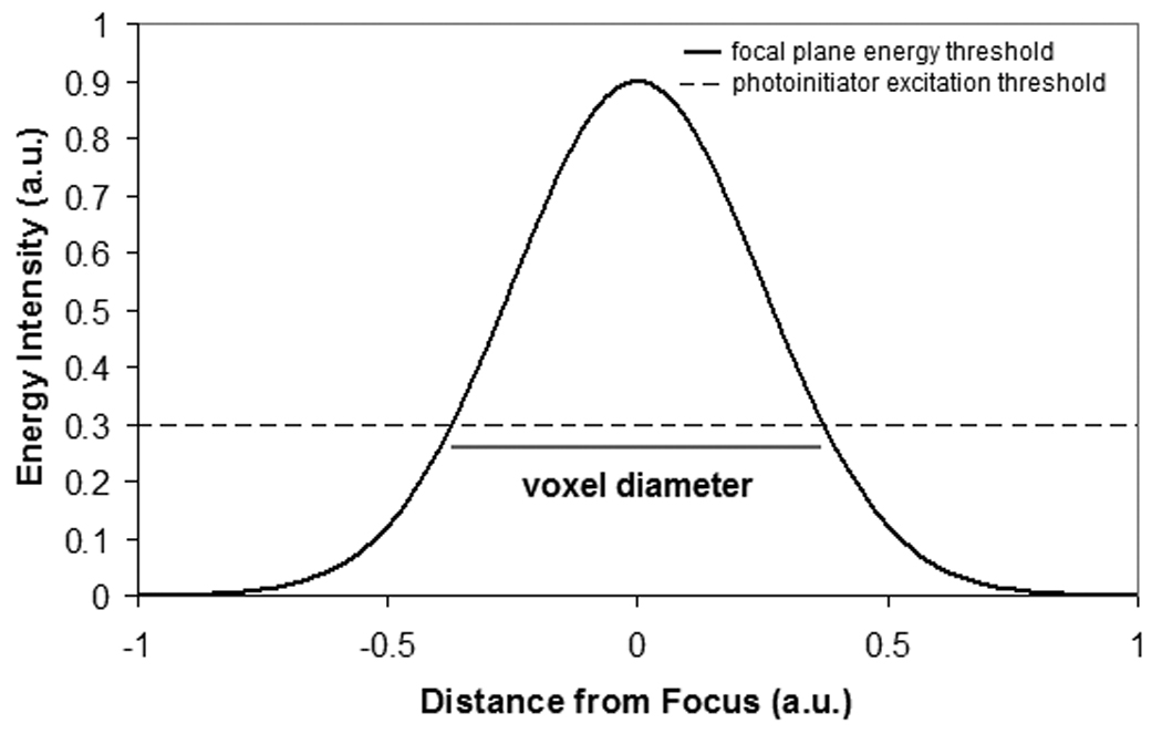
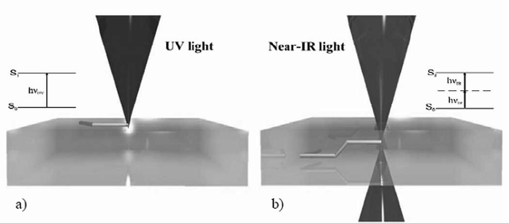
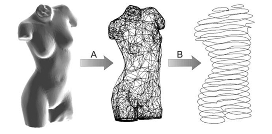
(a) Schematic of the two photon polymerization process. The energy distribution is a Gaussian shape. The radius of the polymerization voxel corresponds to the position at which the energy intensity exceeds the excitation threshold of the photoinitiator. (b) Single photon versus two photon polymerization. Single photon polymerization is limited to the surface of a given material. On the other hand, two photon polymerization may occur within a given material. (c) Schematic of the rapid prototyping process. In the first step, a computer-aided design program is used to prepare a STL format file. The STL format file is subsequently used to prepare a layer-by-layer contour of the structure. The structure is fabricated by rastering the laser in order to fill the area contained within the contours.
The desired structure is produced by selective polymerization of material along a laser trace, which is moved in three dimensions within the resin (Figure 2b) [87]. A computer-aided design (CAD) model of the desired structure is initially sliced into layers. Each layer is subsequently written in the photosensitive resin by rastering the laser path in order to fill in the contour of each layer (Figure 2c). Customized software for controlling the laser path may be used to fabricate complicated structures such as circles or spirals [90]. Processing of the photosensitive resin involves one of the following mechanisms: (a) by moving the photosensitive resin while keeping the laser stationary, or (b) by moving the laser pulses within the resin using a galvano-scanner [91–93]. Galvano-scanners may be used to direct laser-material interaction in two dimensions; movement of the substrate may be used to adjust the depth of laser-material interaction within the resin. The numerical aperture of the objective limits the overall dimensions of structures fabricated using a galvano-scanner. A piezo-electric stage provides a larger travel range; however, writing with a galvano-scanner is more rapid as well as more accurate than writing with a piezo-electric stage. A system containing a galvano-scanner and piezoelectric stages provides the advantages of both techniques. For example, a galvano-scanner may be used to fabricate a single microneedle while a piezoelectric stage may be used to translate a surface in two dimensions for fabrication of microneedle arrays [10, 91].
Two photon polymerization allows for polymerization within volumes that are smaller than the laser wavelength [93–96]. Structures with <100 nm features have been fabricated (a) by using photoinitiators that exhibit high initiating efficiency; (b) by controlling the incident laser power; and (c) by modifying the laser focus scan speed [97–99]. Other factors that determine minimum feature size include laser focus spot size, laser wavelength, and numerical aperture [89]. The polymerization threshold energy may be modified through selection of an appropriate photoinitiator; the other parameters may be used to alter the height of the energy distribution and the width of the energy distribution. Since focusing is performed by passing the laser pulses through an objective, the resolution of two photon polymerization is readily scalable through selection of an appropriate objective. For example, a 5 × objective may be used to prepare voxels with single-digit micrometer diameters [93]. Since there is an inverse correlation between fabrication time and voxel size for a given structure, scalable processing may be used to maximize processing efficiency and minimize processing costs.
Microneedles for drug delivery must be greater than 100 µm in length since the stratum corneum is flexible. In addition, the thickness of the stratum corneum varies in thickness with age, location, and skin condition [100]. Longer (>700 µm) microneedles may be used for withdrawal of blood from dermal blood vessels. Several studies have examined the relationships between microneedle geometry and fracture properties. For example, Davis et al. demonstrated that the interfacial area of the microneedle tip and the microneedle insertion force exhibited a linear relationship [101]. They showed that the microneedle wall thickness was directly related to the microneedle fracture force. In addition, they demonstrated that the microneedle wall angle was directly related to the microneedle fracture force. They also demonstrated that the ratio of fracture force to insertion force, also known as the safety margin, increased as the microneedle tip radius was reduced. Aoyagi et al. also found that lower microneedle penetration forces were associated with smaller tip angles [64]. In addition, Moon et al. suggested that microneedles must exhibit high aspect ratio shafts, sharp as well as tapered tips, small surface areas, and out-of-plane structures in order to meet structural requirements [52]. Griss et al. have shown that out-of-plane microneedles, which contain flow channels that are positioned off-center with respect to the needle tip, do not suffer from obstructions caused by loose skin [102]. Two photon polymerization is commonly used for fabricating arrays of microneedles. Microneedle arrays are favored over solitary microneedles since they provide a larger surface area over which a pharmacologic agent may be delivered or a biological fluid may be extracted. For example, microneedle arrays offer a greater probability of directly reaching blood vessels in the dermis for extraction of biological fluids. In addition, microneedle arrays provide redundancy in case individual needles are fractured or obstructed during handling or insertion [103] Finally, microneedle arrays are also less susceptible to fracture if they are exposed to shear forces since the forces are distributed over a wider area [102].
3. Two Photon Polymerization of Microneedles
In order to be compatible with two photon polymerization, a material must fulfill two requirements. First, the material must be capable of being polymerized by means of two photon absorption either in unmodified form or with the assistance of a photoinitiator. Second, the material must be transparent to the wavelength of the laser [6]. Fortunately, many materials satisfy these requirements. Materials that have been shown to be compatible with two photon polymerization include but are not limited to SU-8 photoresist [99], methacryloxypropyl trimethoxysilane- zirconium propoxide copolymer [90], organically modified ceramic materials [1, 77, 79–80, 74, 91], ethoxylated (6) trimethylolpropane triacrylate [88], polyethylene glycol diacrylate [71,88], as well as other acrylate- and methacrylate-based polymeric materials [6].
The first microneedles directly produced by two photon polymerization were made from Ormocer® (organically modified ceramic) materials [10]. These amorphous materials were originally prepared by the Fraunhofer-Institut für Silicatforschung (Wurzburg, Germany) using sol-gel processes. Ormocer® materials are prepared from urethane- and thioether (meth)-acrylate alkoxysilane precursors. The inorganic components in Ormocer® materials crosslink and form networks through condensation of organically modified alkoxysilane groups [104]. The organic components in Ormocer® materials crosslink through light-initiated processes as well as other processes [104]. Interactions between the ceramic and polymer components prevent separation of Ormocer® material into separate phases. X-ray diffraction confirmed that Ormocer® material fabricated with two photon polymerization exhibits an amorphous structure [10]. In addition, these interactions provide Ormocer® materials with chemical and thermal stability. Ormocer® materials remain stable to 350° C in an oxygen atmosphere and 415° C in a nitrogen atmosphere [105]. The mechanical properties for Ormocer® materials may be varied between those of ceramics and those of polymers by varying several parameters, including the amount of organic network modifying elements, the amount of inorganic network modifying elements, the spacer length that connects the organic crosslinking sites and the inorganic crosslinking sites, and the concentration of fillers. In addition, Ormocer® materials exhibit less shrinkage (~2%) than other sol-gel materials because of the stability of the inorganic network and the inclusion of fillers [106]. Many other materials prepared by sol–gel processing exhibit high (>20%) volume shrinkage during curing, network densifying, or solvent removal steps; these processes may lead to significant mechanical stresses, cracks, as well as other defects. Ormocer®- based matrix components (Definite™) and Ormocer®- based light-curable dental composites (Admira™) are presently utilized in restorative dentistry. Carboxy-modified Ormocer® materials are also utilized as matrix materials in light-curable glass ionomer cements [106].
In vitro assays, such as the 3{4,5-dimethylthiazol-2-yl}-2,5-diphenyltetrazolium bromide (MTT) assay, have been used to examine cell growth on Ormocer® materials [107, 108]. Live/dead assays demonstrated that polymerized Ormocer® surfaces do not significantly impair cell viability or growth rates for B35 neuroblast-like cells and HT1080 epithelial-like cells [10]. In addition, the MTT assay was used to examine cell proliferation on two organically modified ceramic materials, Ormocore® and Ormocer® US-S4 [91, 109]. This assay involves the reduction of a yellow tetrazolium salt (MTT) to a purple formazan dye by mitochondrial succinnic dehydrogenase. Both materials were shown to support human epidermal keratinocyte growth. No significant differences between human epidermal keratinocyte growth on organically modified ceramic surfaces and on control surfaces were noted. These results suggest that Ormocore® and Ormocer® US-S4 materials processed using two photon polymerization do not impair human epidermal keratinocyte viability or growth.
Nanoindentation of Ormocer® US-S4 material provided hardness and Young’s modulus values of ~90 MPa and ~2100 MPa, respectively [109]. Considerable viscoelastic/plastic creep as well as viscoelastic recovery behavior were observed during testing. Park et al. suggested that microneedles fabricated using materials with Young’s modulus values greater than ~1 GPa exhibit fracture forces that exceed microneedle insertion forces [63, 101]. Their work also suggests that microneedles fabricated using materials with higher Young’s modulus values may provide larger microneedle failure forces. The high hardness and modulus values observed in Ormocer® US-S4 material may be attributed to the strong interlinkages between ceramic and polymer components in the material.
Figure 3 contains a scanning electron micrograph of an microneedle array fabricated out of Ormocer® organically modified ceramic material by means of two photon polymerization [110]. The microneedles within this array exhibit excellent microneedle-to-microneedle uniformity. Doraiswamy et al. fabricated a ten-by-ten hollow microneedle array out of Ormocer® US-S4 material using two photon polymerization [10]. The microneedles in this array demonstrated base diameters of 200 µm. The microneedle walls tapered linearly to sharp tips over needle lengths of 750 µm. These microneedles demonstrated much larger wall thicknesses than thin-walled microneedles created using conventional lithography-based techniques. Compression testing of the microneedles against porcine skin showed that the microneedles remained intact and did not exhibit fracture after microneedle-skin interaction. Compression testing of Ormocer® microneedles against polytetrafluroethylene surfaces demonstrated that Ormocer® microneedles undergo elastic and plastic deformation; the nonlinear stress-strain behavior of the devices could be attributed to the presence of the methacrylate groups in the Ormocer® US-S4 material. The flexibility of the two photon polymerization process enables the geometry, size, and mechanical properties of microneedles to be readily modified. Ovsianikov et al. fabricated in-plane hollow microneedle arrays and out-of-plane hollow microneedle arrays (microneedle length=800 µm, microneedle base diameter=150–300 µm) with various aspect ratios out of Ormocer® US-S4 material using two photon polymerization [91]. Off-center microneedles were created by adjusting the position of the bore relative to the central axis. The aspect ratio was altered by varying the diameter of the microneedle base. The diameter of the channel was maintained at a constant value. Figure 4(a), Figure 4(b), and Figure 4(c) contain computer-aided design images of microneedles with (a) 0 µm, (b) 1.4 µm, and (c) 20.4 µm bore-center displacement values. Figure 4(d), Figure 4(e), and Figure 4(f) contain scanning electron micrographs of Ormocer® microneedles with (d) 0 µm, (e) 1.4 µm, and (f) 20.4 µm bore-center displacement values. The microneedles were tapered linearly from the base to the tip. The length of the microneedle (800 µm) would enable use for withdrawal of biological fluids as well as delivery of pharmacologic agents. Ripple-like features were observed on the microneedle walls. These features were attributed to layer-by-layer processing of the structures. The ripple-like features may be eliminated by increasing the number of the layers used for microneedle fabrication. Compression testing of several in-plane and out-of-plane hollow Ormocer® microneedles against porcine skin showed that these microneedle arrays were able to porcine adipose tissue without fracture. The tips of the microneedles exhibited bending during the compression; this elastic behavior was attributed to the presence of methacrylate groups in the Ormocer® US-S4 material. Compression testing of in-plane and out-of-plane hollow microneedles against polytetrafluroethylene surfaces revealed that higher load values were required to fracture microneedles with larger base diameter values. In addition, off-center microneedles exhibited sharp needle tips and the low penetration threshold values. Doraiswamy et al. also used two photon polymerization to fabricate Ormocer® microneedles with 3:1, 3.5:1 and 4:1 aspect ratios [109]. These microneedles were fabricated by varying the microneedle length while maintaining the base diameter of 150 µm as well as the inner channel diameter.
Figure 3.
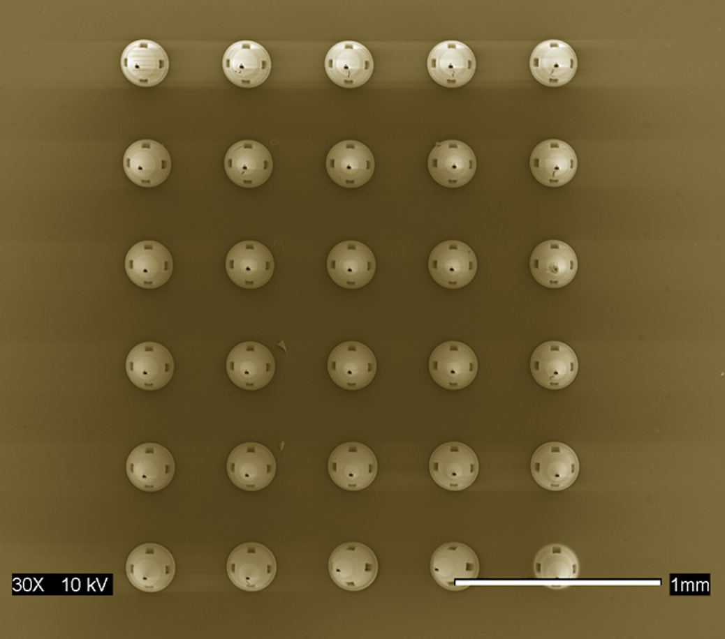
Scanning electron micrograph of microneedle array fabricated out of Ormocer® organically-modified ceramic material using two photon polymerization. Reprinted from American Ceramic Society Bulletin, Vol. 88, page 22, Copyright 2009, with permission from the American Ceramic Society.
Figure 4.
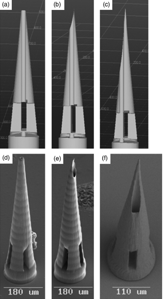
Computer aided design diagrams of hollow Ormocer® microneedles with (a) 0 µm, (b) 1.4 µm, and (c) 20.4 µm needle center-pore displacement. Scanning electron micrographs of hollow Ormocer® microneedles with (a) 0 µm, (b) 1.4 µm, and (c) 20.4 µm needle center-pore displacement. Reprinted from International Journal of Applied Ceramic Technology, Vol. 4, Ovsianikov et al, Two photon polymerization of polymer–ceramic hybrid materials for transdermal drug delivery, 22–29, Copyright 2007, with permission from John Wiley & Sons Inc.
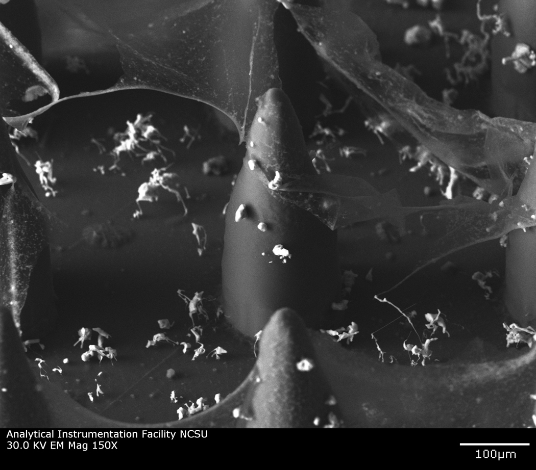
Microneedles with complex geometries, including rocket-like and mosquito-fascicle-like shapes, may be fabricated using two photon polymerization. For example, microneedles with a rocket-like shape consisting of a cylindrical shaft and support braces have been fabricated using two photon polymerization (Figure 4a). This needle geometry exhibits relatively small tip angle; as previously mentioned, lower microneedle penetration forces are associated with smaller microneedle tip angles [60, 111]. Two photon polymerization has also been used for fabrication of microneedles with biomimetic attributes. For example, the fascicle of the mosquito exhibits sub-micrometer features that enhance skin penetration. The fascicle contains several organs, including the hypopharynx, labrum (feeding tube), mandibles, and maxillae. The maxillae exhibits serrated features, which facilitate skin penetration at relatively low forces [112, 113]. Aoyagi et al. used finite element modeling as well as experimental studies to show that the serrated tips provide enhanced stress concentrations that facilitate skin penetration [64]. An Ormocer® mosquito-like microneedle was fabricated by means of two photon polymerization [114, 115].Figure 5b shows a scanning electron micrograph of the Ormocer® mosquito-like microneedle; serrated features on the microneedle tip are clearly observed.
Figure 5.
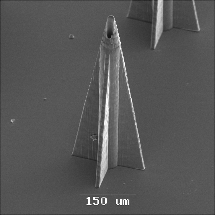

Scanning electron micrographs of microneedles with complex geometries. (a) Scanning electron micrograph of an Ormocer® rocket-shaped microneedle fabricated using two photon polymerization. The small cross-sectional area minimizes the skin penetration force. (b) Scanning electron micrograph of an Ormocer® mosquito geometry microneedle fabricated using two photon polymerization. The serrated tip provides stress concentrations, which decrease the skin penetration force. Image used with permission of the copyright owner (B. N. Chichkov).
Ormocer® microneedles fabricated using two photon polymerization have been used for delivery of fluorescein-conjugated biotin and PEG-amine quantum dot solutions to cadaveric porcine skin. Quantum dots are 2 nm-10 nm diameter semiconductor nanoparticles that are composed of II–VI or III–V semiconductor materials [116]. Quantum dots demonstrate large molar extinction coefficients and high quantum yield values; as a results, these materials provide higher brightness than conventional fluorophores [117]. Quantum dots may be used to detect cancer via passive mechanisms (e.g., quantum dots may be preferentially retained within tumor cells) or active mechanisms (e.g., quantum dots may be conjugated with tumor-specific molecules that enable attachment to tumor cells) [118–121]. These materials may not be administered in oral form since they may be confined within the intestine, liver, kidneys, or lungs before entering systemic circulation [122–123]. In recent work, Ormocer® microneedles successfully created pores in the stratum corneum layer, which facilitated transdermal administration of PEG-amine quantum dot solution [109]. Microneedles created using two photon polymerization were shown to enable distribution of PEG-amine quantum dot solution to deep epidermis and dermis layers of cadaveric porcine skin after sixty minutes. Figure 6 contains DIC-fluorescence micrographs of porcine skin sections that were obtained five minutes after fluorescein-conjugated biotin administration and sixty minutes after fluorescein-conjugated biotin administration. The Ormocer® microneedles enabled distribution of fluorescein-conjugated biotin to deep epidermis and dermis layers of cadaveric porcine skin after sixty minutes. It is anticipated that microneedles with different dimensions may provide control over transport of pharmacologic agents into specific epidermal, dermal, or subdermal layers.
Figure 6.
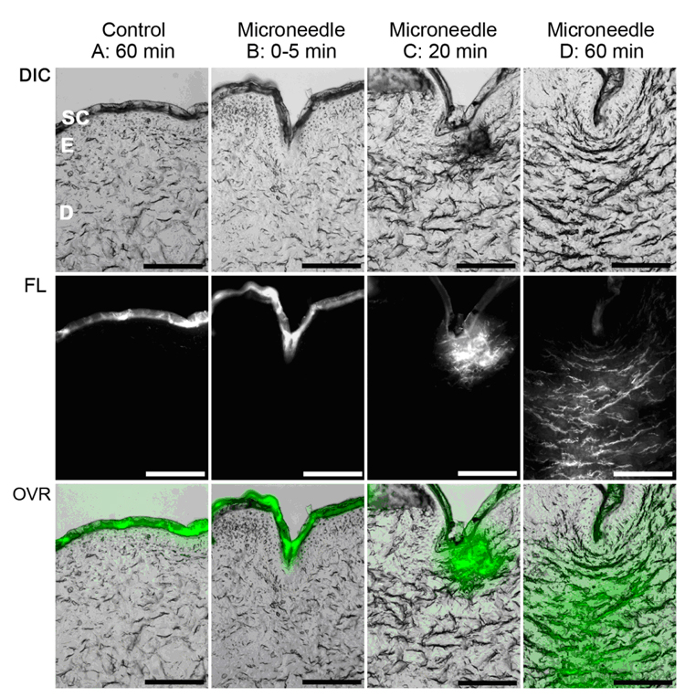
(a) DIC-fluorescence confocal microscopy images showing administration of fluorescein-conjugated biotin solution to porcine skin. The center columns and the right column demonstrate that administration of fluorescein-conjugated biotin solution to deeper layers of porcine skin was enabled by a microscale pore, which was created by an Ormocer® microneedle. The left column shows administration of fluorescein-conjugated biotin solution to porcine skin without microneedle enhancement. The topically administered fluorescein-conjugated biotin solution remained on the skin surface. Top row: DIC single-channel demonstrates stratum corneum (SC), deeper epidermis (E), and dermis (D) layers of the skin. Bottom row: DIC-fluorescence overlay (OVR) shows distribution of fluorescein-conjugated biotin solution within various skin layers. Scale bar equals 100 µm. (b) Scanning electron micrograph of polyethylene glycol 600 diacrylate miconeedles after exposure to platelet rich plasma. No protein aggregation and no platelet aggregation were observed on the polyethylene glycol 600 diacrylate microneedles. Small, widely scattered crystals were observed on the surface; the presence of sodium, chlorine, and phosphorus in energy dispersive X-ray spectroscopy data suggests that sodium chloride crystals precipitated from the platelet rich plasma.
Two photon polymerization followed by subsequent molding steps may be utilized for creating solid microneedles as well as solid microneedle arrays [61, 65, 66]. The chemical, mechanical, and physical properties of the materials used to fabricate the devices in this indirect rapid prototyping process are conserved because these materials do not undergo two photon polymerization processing. In addition, microneedles may be fabricated out of a broader range of materials that are incompatible with two photon polymerization. LaFratta et al. showed that an indirect rapid prototyping process involving photopolymerization and micromolding may be used for fabrication of three-dimensional microscale structures [124]. Gittard et al. recently used a two photon polymerization and polydimethyl siloxane micromolding for microneedle fabrication [61]. Two photon polymerization was used to make a master structure, which was subsequently used to make a negative mold from poly(dimethyl siloxane). The negative mold was then used to cast microneedles out of photoreactive acrylate-based polymer (Envisiontec, Ferndale, MI). The acrylate-based polymer is a water-resistant material that exhibits flexural strength of 2,300 MPa (D790M test method), hardness of 83 Shore (D2240 test method), tensile strength of 57.8 MPa (D638M test method), Young’s modulus of 2,400 GPa (D638M test method), and glass transition temperature of 109° C (E1545-00 test method); it should be noted that this material is opaque and as such may not be processed using two photon polymerization. The solid microneedles exhibited base diameters of 150 µm and lengths of 500 µm. The microneedle array demonstrated good microneedle-to-microneedle uniformity. In most cases, microscale features in the microneedles were consistent with dimensions described in the computer-aided-design file; however, some of the microneedles exhibited slight deviations from the dimensions described in the computer-aided-design file. For example, the tips of a small fraction of microneedles in the microneedle arrays exhibited truncated features. Twenty-four hour MTT assays indicated that human epidermal keratinocyte growth on the acrylate-based polymer surfaces was similar to that on control surfaces. The 5 × 5 acrylate-based polymer microneedle arrays were able to withstand an axial load of 10 N without fracture; this result suggests that acrylate-based polymer microneedle arrays possess suitable compressive strength for use in transdermal drug delivery. Ex vivo studies demonstrated that microneedle arrays successfully penetrated human stratum corneum and epidermis. Irregular ~58 µm diameter pores were observed in the human stratum corneum and epidermis. The pores created by the microneedles were shown to completely penetrate the stratum corneum layer and enter the deeper epidermal layers. The pores became smaller after microneedle removal; however, they remained open and retained capability for use as conduits for pharmacologic agents. Two photon polymerization-micromolding provides represents a scalable approach that may be used to create solid microneedles and microneedle arrays out of a broader range of materials than two photon polymerization.
The two photon polymerization-micromolding process has also been used to fabricate microneedles out of polyethylene glycol diacrylate. Once polymerized, polyethylene glycol is a relatively stable material since hydrolytic degradation can only take place at crosslink points [125]. Polyethylene glycol exhibits inert behavior since uncharged hydrophilic groups are exposed in aqueous solutions. Miyano et al. demonstrated that microneedles fabricated from polyethylene glycol were able to penetrate a living human skin model; their work suggested that polyethylene glycol microneedles exhibited sufficient mechanical strength to be form conduits through the stratum corneum [126]. There are minimal concerns regarding fracture of polyethylene glycol microneedles during skin insertion since the devices undergo hydrolytic degradation on the skin surface. Furthermore, polyethylene glycol microneedles may be destroyed by means of boiling. Takano et al. recently demonstrated insertion of polyethylene glycol microneedles into a wet cultured human skin model under biaxial tension; shortening of microneedles were attributed to hydrolysis [127]. They describe placement of polyethylene glycol microneedles on the skin surface for extended periods of time; hydrolysis of polyethylene glycol microneedles may allow for gradual release of pharmacologic agents. Gittard et al. recently fabricated polyethylene glycol diacrylate microneedle arrays using photopolymerization-micromolding, which exhibited base diameters of 150 µm, lengths of 500 µm, tip angles of 45°, and >10 µm tip diameters; good correspondence with the master structure was observed [65]. Truncated microneedle tips as well as voids within microneedles were observed in a small fraction of the microneedles within the microneedle arrays. These defects were attributed to incomplete degassing of the unpolymerized polyethylene glycol solution. Gittard et al. showed that polyethylene glycol 600 diacrylate microneedles exposed to human platelet rich plasma did not exhibit protein aggregation or platelet aggregation [65]. Several investigators have demonstrated that polyethylene glycol diacrylate-based materials possess nonspecific resistance to cell adhesion and protein adsorption [128–130]. The ability of polyethylene glycol surfaces to resist biological molecules is attributed to formation of hydrogen bonds with water molecules; this process is enhanced by steric stabilization. Steric stabilization is a repulsive force associated with (a) the loss in conformational freedom of polyethylene glycol chains when proteins move closer to polyethylene glycol surfaces as well as (b) osmotic interactions between proteins and polyethylene glycol surfaces [131]. These properties are appealing for microneedles, since protein fouling and cell adhesion can impede pharmacologic agent transport from microneedles to adjacent tissues.
One important factor that is limiting clinical use of microneedles and microneedle arrays is the risk of infection. The stratum corneum prevents a variety of foreign materials, including microorganisms, from entering the body. Pathogenic microorganisms such as Staphylococcus aureus reside on the surface of the skin; a pore in the stratum corneum created by a microneedle could enable microorganisms to cause local or systemic infection [132–134]. For example, Birchall noted that the channels formed by microneedles through the stratum corneum could increase the risk of infection [135]. He also noted that damage to the stratum coreum is transient as well as minor in nature; however, the skin repair mechanisms in response to microneedle-fabricated pores are not completely understood. Donnelly et al. recently examined the movement of microorganisms across microneedle-fabricated pores by means of in vitro models [136]. They demonstrated that pathogenic microorganisms, including Candida albicans, Pseudomonas aeruginosa and Staphylococcus epidermidis, adhered to microneedle arrays during insertion into excised porcine skin. It should be noted that no microorganisms entered viable epidermis layers by means of microneedle-fabricated pores. In addition, the number of microorganisms that penetrated microneedle-punctured Silescol® membranes was an order of magnitude lower than the number of microorganisms that penetrated hypodermic needle-punctured Silescol® membranes. They stated that microneedle-fabricated pores would not lead to infections under normal circumstances in immune-competent patients; however, they suggested that patient safety would be enhanced by manufacturing microneedles using sterile techniques. The risk of infection associated with microneedle-fabricated pores may also be reduced by imparting microneedles with antimicrobial properties.
Antimicrobial microneedles may be fabricated out of composite materials that contain biocompatible polymers such as polyethylene glycol as well as conventional antimicrobial agents such as gentamicin sulfate. Gentamicin is broad spectrum antimicrobial agent that exhibits efficacy against Gram negative organisms as well as some Gram positive organisms. It is commonly used for treatment of pyodermas and other skin infections; for example, Changez et al. showed that gentamicin is active against Staphylococcus bacteria that are commonly found on the skin [137]. Gentamicin is hydrophilic material; aqueous suspensions containing polyethylene glycol and gentamicin may be readily produced [138]. Gittard et al. used photopolymerization-micromolding to fabricate microneedle arrays out of a photosensitive material containing polyethylene glycol 600 diacrylate, gentamicin sulfate, and a photoinitiator. An agar plating assay revealed that the gentamicin-doped polyethylene glycol 600 diacrylate microneedle inhibited growth of Staphylococcus aureus bacteria. The 26.8 mm diameter zone of inhibition indicated that gentamicin sulfate was released from the microneedle array. Acellular bubble-like structures were observed on the agar surface; these features were attributed to hydrogel degradation.
Antimicrobial microneedles may also be prepared by coating microneedles with thin films of antimicrobial materials such as silver. Silver exhibits broad-spectrum antimicrobial properties against viruses, fungi, and bacteria (e. g., Staphylococcus aureus); this activity is attributed to disruption of electron transport and interruption of DNA replication [139–146]. Silver also reduces inflammatory activity as well as facilitates healing in wounds. In addition, Demling et al. suggest that silver increases re-epithelialization compared to a conventional antimicrobial solution [147–149]. Coatings containing antimicrobial materials may be applied to microneedle surfaces using a physical vapor deposition process known as pulsed laser deposition [150]. In pulsed laser deposition, a solid target is vaporized using a high energy excimer laser; the average kinetic energies of atomic and molecular species produced by excimer laser ablation is 100 kT-1000 kT; kT is equal to 26 meV at room temperature [151, 152]. The high energies of the laser-ablated species serve to promote adhesion of the film as well as chemical reactions between the substrate and the film [153]. Pulsed laser deposition is ideally suited for film deposition on polymeric substrates since many coatings may be prepared at room temperature. For example. Gittard et al. fabricated microneedles with antimicrobial functionality using a combination of two photon polymerization-micromolding and pulsed laser deposition [66]. In this study, pulsed laser deposition was used to deposit silver thin films on Ormocer® microneedle arrays, which were fabricated using two photon polymerization-micromolding. No pinholes or other nonuniformities were noted in the silver thin films on the silver-coated microneedles. MTT studies showed that human epidermal keratinocyte viability on the silver-coated Ormocer® surfaces was similar to that on uncoated Ormocer® surfaces. An agar diffusion assay was used to evaluate the antimicrobial performance of the silver-coated Ormocer® microneedle array and the uncoated Ormocer® microneedle array. On the plate containing the uncoated Ormocer® microneedle array, S. aureus growth was noted directly beneath the microneedle array. On the plate containing the silver-coated Ormocer® microneedle array, an absence of S. aureus growth beneath the microneedle array was noted. In addition, inhibited growth was noted in the agar that surrounded the microneedle array; the presence of a zone of inhibition suggests that silver was released into agar. The results of these studies suggest that the photopolymerization-micromolding process may be used alone or in combination with pulsed laser deposition to fabricate microneedles that exhibit antimicrobial functionality.
4. Other Medical Applications of Two Photon Polymerization
Two photon polymerization may also be used to fabricated a wide variety of microstructured and nanostructured medical devices; for example, two photon polymerization been used to create patient-specific medical prostheses as well as scaffolds for tissue engineering. Ovsianikov et al. utilized two photon polymerization for fabrication of ossicular replacement prostheses, which are used to restore sound conduction in the middle ear. Three bones in middle ear, the malleus, the incus, and the stapes, transmit sounds from the tympanic membrane to the inner ear. Discontinuity or fixation of these bones may result in conductive hearing loss. Conventional implants are produced in several standardized shapes and sizes; however, these designs do not take into account individual patient anatomy. These prostheses are shaped during implantation procedures; the intraoperative shaping process requires additional operative time. One method for lowering the cost as well as increasing the success of ossicular replacement prostheses involves the development of patient-specific implants. For example, imaging (e.g., computed tomography or magnetic resonance imaging) and analysis software may be employed to generate an implant with an appropriate geometry and size for a particular patient [154]. Two photon polymerization enables prosthesis to be fabricated with smaller features than stereolithography, selective laser sintering, fused deposition modeling, or other rapid prototyping techniques. Ovsianikov et al. demonstrated fabrication of total ossicular replacement prostheses out of Ormocer® US-S4 material using two photon polymerization [155]. The proestheses were similar in design to a commercially available total ossicular replacement prostheses (Kurz Medical Inc., Dusslingen, Germany). Conical structures were fabricated on the head of the prosthesis; these structures were intended to reduce device migration, improve cell adhesion, and decrease the likelihood of tympanic membrane perforation. The disk-shaped headplate of the prosthesis was intended to be placed under the tympanic membrane. The shaft of the prosthesis connected the footplate of the stapes with the undersurface of the tympanic membrane; this structure was intended to enable sound conduction. An Ormocer® ossicular replacement prosthesis was placed on the footplate of the stapes and underneath the tympanic membrane in a commercially obtained de-frozen human head; this prosthesis was implanted and removed from the implantation site without fracture. A total ossicular replacement prosthesis fabricated using two-photon polymerization may be prepared with an appropriate geometry for a given patient; the prosthesis may be fabricated with features that (a) maintain a small angle between the stapes and the prosthesis; (b) place the prosthesis on the center of the footplate; and (c) properly align the prosthesis with respect to the surrounding structures.
Two photon polymerization may also be used to develop artificial tissues and organs. Tissue and organ substitutes may be created by placing living cells within three-dimensional scaffolds, which guide cell development. The cell-seeded scaffolds are subsequently placed in bioreactors, which provide nutrients that enable cell proliferation within the scaffolds. The cell-seeded scaffolds are later implanted within the body, where the tissue substitutes can enable to body to resume normal function. Rapid prototyping technologies such as two photon polymerization hold great potential for fabrication of artificial tissues and organs with appropriate geometries and mechanical properties for a given individual. For example, Doraiswamy et al. fabricated three-dimensional tissue engineering scaffolds with Lego®-like interlocking structures out of Ormocer® US-S4 material [10]. The Lego®-like interlocking tissue engineering scaffolds contained arrays of 75 µm diameter, 20µm tall cylindrical pillar structures on both sides of a flat Ormocer® chip. The cylindrical structures could facilitate layer-by-layer stacking of scaffolds for development of three-dimensional tissues. Cells seeded on these structures were oriented along the pillar walls, and were found to gradually increase in number over time. 100% of the B35 neuroblast-like cells remained viable 48 hours after placement on the Ormocer® substrates. The cell interaction and cell proliferation properties of B35 neuroblast-like cells on Lego®-like interlocking tissue engineering scaffolds suggest that Ormocer® structures fabricated using two photon polymerization may provide an alternative to conventional scaffolds for creating multilayered artificial tissues and organs. Proliferation of endothelial, neuroblastoma, granulosa, and keratinocyte cells on scaffolds fabricated using two photon polymerization has also been examined [10, 111, 156, 157]. In addition, two photon polymerization has been used to fabricate small storage capsules on metal stents; these structures may enable localized delivery of pharmacologic agents at the implantation site [87].
5. Conclusions
Two photon polymerization is a novel rapid prototyping technique that may be used to fabricate microneedles as well as microneedle arrays with a wider range of geometries than reactive ion etching, lithography-electroforming-replication, or other conventional microelectronics-based technologies. The two photon polymerization process relies on temporal and spatial overlap of photons in order to achieve photopolymerization and hardening of material within highly-localized and well-defined volumes. Our results suggest that two photon polymerization is able to create microneedles with a wide range of geometries, including in-plane microneedles, out-of-plane microneedles, mosquito fascicle-shaped microneedles, and rocket-shaped microneedles. Ormocer® microneedles fabricated using two photon polymerization penetrated cadaveric porcine adipose tissue without fracture. Penetration of the stratum corneum layer by Ormocer® microneedles enabled transdermal delivery of PEG-amine quantum dot solution and fluorescein-biotin solution to the deep epidermis and dermis layers of porcine skin; microneedles were shown to enable more rapid distribution than topical administration. A two photon polymerization-polydimethyl siloxane micromolding process has been used to fabricate solid microneedles out of a photo-reactive acrylate-based polymer, polyethylene glycol 600 diacrylate, and Ormocer® material; this indirect rapid prototyping process is more suitable for large-scale processing than two photon polymerization. Solid microneedle arrays fabricated out of photo-reactive acrylate-based polymer were successfully able to create pores in human stratum corneum and epidermis; these arrays were able to withstand an axial load of 10 N without fracture. Scanning electron microscopy revealed no platelet aggregation on the surfaces of platelet rich plasma-exposed polyethylene glycol 600 diacrylate microneedles. Antimicrobial solid microneedles were fabricated out of a photosensitive material containing polyethylene glycol 600 diacrylate, gentamicin sulfate, and a photoinitiator using two photon polymerization-micromolding. Antimicrobial solid microneedles were with silver coatings were fabricated using a combination of two photon polymerization-micromolding and pulsed laser deposition. These studies suggest that the geometry as well as the mechanical properties of microneedles may be rapidly optimized using two photon polymerization for depth-dependent transdermal delivery of pharmacologic agents. Several other microstructured medical devices with unique geometries, including ossicular replacement prostheses and tissue engineering scaffolds, have been successfully fabricated using two photon polymerization of Ormocer® organic-inorganic hybrid materials.
6. Expert Opinion
Over the next several years, microneedles will find greater use for delivery of nucleic acid- and protein-based pharmacologic agents that cannot be administered in enteral form. Over the past several decades, microneedle devices have been prepared using reactive ion etching, lithography-electroforming-replication, or other microelectronics-based fabrication techniques. Several small and large companies are in the process of bringing their microneedle-based devices to market for transdermal delivery of vaccines and hormones. However, numerous factors are limited the commercial viability of microneedles prepared using microelectronics-based fabrication techniques. In recent years, two photon polymerization has been used to fabricate microneedles as well as microneedle arrays with a wider range of geometries than conventional microelectronics-based technologies. Perhaps most advantageous attribute of two photon polymerization is that it provides a high degree of control over microneedle geometry. Microneedles must not fracture during penetration into the skin, use, or removal from the skin. As mentioned earlier, many of the problems associated with microneedles prepared using conventional techniques may be attributed to the fact that these techniques have inherent limitations in terms of fabricating microneedles that exhibit large wall thicknesses as well as other fracture-resistant geometries. In addition, two photon polymerization is compatible with many photosensitive resins, which are widely available and may be obtained at low cost. Furthermore, two photon polymerization can be performed in conventional facilities; for example, two photon polymerization can potentially be set up in a conventional clinical environment (e.g., an outpatient medical office) for fabrication of patient-specific drug delivery devices that conform to a given patient's anatomy and medical condition. Several commercialization and device-related challenges will need to be considered in the coming years. For example, techniques for creating microneedles that exhibit a clinically acceptable degree of uniformity from batch to batch must be developed. Refinement of microneedle geometry for a given clinical application as well as a specific patient population is also necessary. In addition, optimization of the two photon polymerization processing rate must be undertaken. It should be noted that a combination of two photon polymerization and micromolding may be directly implemented in current manufacturing environments for large-scale processing of solid microneedles as well as microneedle arrays. Furthermore, work is needed to incorporate multiple functionalities (e.g., monitoring and treatment of multiple chronic diseases) within a single microneedle-based device. Finally, two photon polymerization needs to be cost competitive with conventional techniques. If these obstacles can be overcome, two photon polymerization of microneedles as well as other drug delivery devices may attain commercial significance over the coming decades.
7. Article highlights box
Microneedles are miniaturized lancet-, thorn-, or hypodermic needle-shaped devices that exhibit at least one dimension less than 500 µm; these devices may be used to create pores in the stratum corneum layer of the epidermis.
Over the past several decades, microneedles have been prepared using technologies that originated in the microelectronics and glassware industries.
Numerous factors have limited the commercial viability of microneedles prepared using microelectronics-based fabrication techniques.
Two photon polymerization utilizes ultrashort laser pulses for selective polymerization of photosensitive resins into complex microscale and nanoscale structures.
The first microneedles directly produced by two photon polymerization were made from Ormocer® (organically modified ceramic) materials.
Microneedles with complex geometries, including rocket-like and mosquito-fascicle-like shapes, may be fabricated using two photon polymerization.
Ormocer® microneedles fabricated using two photon polymerization have been used for delivery of fluorescein-conjugated biotin and PEG-amine quantum dot solutions to cadaveric porcine skin.
Two photon polymerization followed by subsequent molding steps may be utilized for creating solid microneedles as well as solid microneedle arrays.
Antimicrobial microneedles may be fabricated out of composite materials that contain biocompatible polymers such as polyethylene glycol as well as conventional antimicrobial agents such as gentamicin sulfate.
Antimicrobial microneedles may also be prepared by coating microneedles with thin films of antimicrobial materials such as silver.
Two photon polymerization may also be used to fabricated a wide variety of microstructured and nanostructured medical devices; for example, two photon polymerization been used to create patient-specific medical prostheses as well as scaffolds for tissue engineering.
Two photon polymerization is a novel rapid prototyping technique that may be used to fabricate microneedles as well as microneedle arrays with a wider range of geometries than reactive ion etching, lithography-electroforming-replication, or other conventional microelectronics-based technologies.
Acknowledgements
The authors wish to acknowledge support from the United States National Science Foundation, the United States National Institutes of Health (1R21DA026980-01), and the United States Department of Defense.
Footnotes
Declaration of interest
The authors state no conflicts of interest and have received no payment in the preparation of this manuscript.
Bibliography
Papers of special note have been highlighted as either of interest (*) or of considerable interest (**) to readers.
- 1.Khafagy ES, Morishita M, Onuki Y, Takayama K. Current challenges in non-invasive insulin delivery systems: A comparative review. Adv Drug Deliv Rev. 2007;59:1521–1546. doi: 10.1016/j.addr.2007.08.019. [DOI] [PubMed] [Google Scholar]
- 2.Brown MB, Martin GP, Jones SA, Akomeah FK. Dermal and transdermal drug delivery systems: Current and future prospects. Drug Deliv. 2006;13:175–187. doi: 10.1080/10717540500455975. [DOI] [PubMed] [Google Scholar]
- 3.Prausnitz MR, Mitragotri S, Langer R. Current status and future potential of transdermal drug delivery. Nat Rev Drug Discov. 2004;3:115–124. doi: 10.1038/nrd1304. [DOI] [PubMed] [Google Scholar]
- 4.Chabri F, Bouris K, Jones T, et al. Microfabricated silicon microneedles for nonviral cutaneous gene delivery. Br J Dermatol. 2004;150:869–877. doi: 10.1111/j.1365-2133.2004.05921.x. [DOI] [PubMed] [Google Scholar]
- 5.Mukerjee EV, Collins SD, Isseroff RR, Smith RL. Microneedle array for transdermal biological fluid extraction and in situ analysis. Sensor Actuat A. 2004;114:267–275. [Google Scholar]
- 6.Kaushik S, Hord AH, Denson DD, et al. Lack of pain associated with microfabricated microneedles. Anesth Analg. 2001;92:502–504. doi: 10.1097/00000539-200102000-00041. [DOI] [PubMed] [Google Scholar]
- 7.Prausnitz MR, Langer R. Transdermal drug delivery. Nat Biotechnol. 2008;26:1261–1268. doi: 10.1038/nbt.1504. [DOI] [PMC free article] [PubMed] [Google Scholar]
- 8.Gowthamarajan K, Kulkarni GT. Oral insulin – fact or fiction?: Possibilities of achieving oral delivery for insulin. Resonance. 2003;8:38–46. [Google Scholar]
- 9.Nordquist L, Roxhed N, Griss P, Stemme G. Novel microneedle patches for active insulin delivery are efficient in maintaining glycaemic control: an initial comparison with subcutaneous administration. Pharma Res. 2007;24:1381–1388. doi: 10.1007/s11095-007-9256-x. [DOI] [PubMed] [Google Scholar]
- 10. Doraiswamy A, Jin C, Narayan RJ, et al. Two photon induced polymerization of organic-inorganic hybrid biomaterials for microstructured medical devices. Acta Biomater. 2006;2:267–275. doi: 10.1016/j.actbio.2006.01.004. ** First report of using two-photon polymerization to produce microneedles
- 11. Prausnitz MR. Microneedles for transdermal drug delivery. Adv Drug Del Rev. 2004;56:581–587. doi: 10.1016/j.addr.2003.10.023. *Comprehensive review of microneedle technology
- 12.Gill HS, Denson DD, Burris BA, Prausnitz MR. Effect of microneedle design on pain in human volunteers. Clin J Pain. 2008;24:585–594. doi: 10.1097/AJP.0b013e31816778f9. [DOI] [PMC free article] [PubMed] [Google Scholar]
- 13.Khafagy ES, Morishita M, Onuki Y, et al. Current challenges in non-invasive insulin delivery systems: A comparative review. Adv Drug Deliv Rev. 2007;59:1521–1546. doi: 10.1016/j.addr.2007.08.019. [DOI] [PubMed] [Google Scholar]
- 14.Martano W, Davis SP, Holiday NR, et al. Transdermal delivery of insulin using microneedles in vivo. Pharma Res. 2004;21:947–952. doi: 10.1023/b:pham.0000029282.44140.2e. [DOI] [PubMed] [Google Scholar]
- 15.Lin WQ, Cormier M, Samiee A, et al. Transdermal delivery of antisense oligonucleotides with microprojection patch (Macroflux (R)) technology. Pharm Res. 2001;18:1789–1793. doi: 10.1023/a:1013395102049. [DOI] [PubMed] [Google Scholar]
- 16.Birchall J, Coulman S, Pearton M, et al. Cutaneous DNA delivery and gene expression in ex vivo human skin explants via wet-etch microfabricated microneedles. J Drug Target. 2005;13:415–421. doi: 10.1080/10611860500383705. [DOI] [PubMed] [Google Scholar]
- 17.Coulman SA, Anstey A, Gateley C, et al. Microneedle mediated delivery of nanoparticles into human skin. Int J Pharm. 2009;366:190–200. doi: 10.1016/j.ijpharm.2008.08.040. [DOI] [PubMed] [Google Scholar]
- 18.Cormier M, Johnson B, Ameri M, et al. Transdermal delivery of desmopressin using a coated microneedle array patch system. J Control Release. 2004;97:503–511. doi: 10.1016/j.jconrel.2004.04.003. [DOI] [PubMed] [Google Scholar]
- 19.Gill HS, Prausnitz MR. Coated microneedles for transdermal delivery. J Control Release. 2007;117:227–237. doi: 10.1016/j.jconrel.2006.10.017. [DOI] [PMC free article] [PubMed] [Google Scholar]
- 20.Schuetz YB, Naik A, Guy RH, Kalia YN. Emerging strategies for the transdermal delivery of peptide and protein drugs. Expert Opin Drug Deliv. 2005;2:533–548. doi: 10.1517/17425247.2.3.533. [DOI] [PubMed] [Google Scholar]
- 21.Kobayashi K, Suzuki H. A sampling mechanism employing the phase transition of a gel and its application to a micro analysis system imitating a mosquito. Sens Actuator B. 2001;80:1–8. [Google Scholar]
- 22.Suzuki H, Tokuda T, Kobayashi K. A disposable "intelligent mosquito" with a reversible sampling mechanism using the volume-phase transition of a gel. Sens Actuator B. 2002;83:53–59. [Google Scholar]
- 23.Wang PM, Cornwell M, Hill J, Prausnitz MR. Precise microinjection into skin using hollow microneedles. J Invest Dermatol. 2006;126:1080–1087. doi: 10.1038/sj.jid.5700150. [DOI] [PubMed] [Google Scholar]
- 24.Zahn JD, Deshmukh A, Pisano AP, Liepmann D. Continuous on-chip micropumping for microneedle enhanced drug delivery. Biomed Microdev. 2004;6:183–190. doi: 10.1023/B:BMMD.0000042047.83433.96. [DOI] [PubMed] [Google Scholar]
- 25.Belshe RB, Newman FK, Cannon J, et al. Serum antibody responses after intradermal vaccination against influenza. N Engl J Med. 2004;351:2286–2294. doi: 10.1056/NEJMoa043555. [DOI] [PubMed] [Google Scholar]
- 26.Kenney RT, Frech SA, Muenz LR, et al. Dose sparing with intradermal injection of influenza vaccine. N Engl J Med. 2004;351:2295–2301. doi: 10.1056/NEJMoa043540. [DOI] [PubMed] [Google Scholar]
- 27.Kim YC, Quan FS, Yoo DG, et al. Enhanced memory responses to seasonal H1N1 influenza vaccination of the skin with the use of vaccine-coated microneedles. J Infect Dis. 2010;201:190–198. doi: 10.1086/649228. [DOI] [PMC free article] [PubMed] [Google Scholar]
- 28.Alarcon JB, Hartley AW, Harvey NG, et al. Preclinical evaluation of microneedle technology for intradermal delivery of influenza vaccines. Clin Vaccine Immunol. 2007;14:375–381. doi: 10.1128/CVI.00387-06. [DOI] [PMC free article] [PubMed] [Google Scholar]
- 29.Zhu QY, Zarnitsyn VG, Ye L, et al. Immunization by vaccine-coated microneedle arrays protects against lethal influenza virus challenge. Proc Natl Acad Sci USA. 2009;106:7968–7973. doi: 10.1073/pnas.0812652106. [DOI] [PMC free article] [PubMed] [Google Scholar]
- 30.Ding Z, Verbaan FJ, Bivas-Benita M, et al. Microneedle arrays for the transcutaneous immunization of diphtheria and influenza in BALB/c mice. J Control Release. 2009;136:71–78. doi: 10.1016/j.jconrel.2009.01.025. [DOI] [PubMed] [Google Scholar]
- 31.Van Damme P, Oosterhuis-Kafeja F, Van der Wielen M, et al. Safety and efficacy of a novel microneedle device for dose sparing intradermal influenza vaccination in healthy adults. Vaccine. 2009;27:454–459. doi: 10.1016/j.vaccine.2008.10.077. [DOI] [PubMed] [Google Scholar]
- 32.Haq MI, Smith E, John DN, et al. Clinical administration of microneedles: skin puncture, pain and sensation. Biomed Dev. 2009;11:35–47. doi: 10.1007/s10544-008-9208-1. [DOI] [PubMed] [Google Scholar]
- 33.Bal SM, Caussin J, Pavel S, et al. In vivo assessment of safety of microneedle arrays in human skin. Eur J Pharm Sci. 2008;35:193–202. doi: 10.1016/j.ejps.2008.06.016. [DOI] [PubMed] [Google Scholar]
- 34.Sivamani RK, Stoeber B, Wu GC, et al. Clinical microneedle injection of methyl nicotinate: stratum corneum penetration. Skin Res Technol. 2005;11:152–156. doi: 10.1111/j.1600-0846.2005.00107.x. [DOI] [PubMed] [Google Scholar]
- 35.Wagner AR, Cooper SM. Article of manufacture for intracutaneous injections. US2893392. 1959
- 36.Reaume SE. The use of hydrofluoric acid in making glass microneedles. Science. 1952;116:641. doi: 10.1126/science.116.3023.641. [DOI] [PubMed] [Google Scholar]
- 37.Martanto W, Moore JS, Kashlan O, et al. Microinfusion using hollow microneedles. Pharm Res. 2006;23:104–113. doi: 10.1007/s11095-005-8498-8. [DOI] [PubMed] [Google Scholar]
- 38.Shikida M, Ando M, Ishihara Y, et al. Non-photolithographic pattern transfer for fabricating pen-shaped microneedle structures. J Micromech Microengineering. 2004;14:1462–1467. [Google Scholar]
- 39.Shikida M, Hasada T, Sato K. Fabrication of a hollow needle structure by dicing, wet etching and metal deposition. J Micromech Microengineering. 2006;16:2230–2239. [Google Scholar]
- 40.Wilke N, Mulcahy A, Ye SR, Morrissey A. Process optimization and characterization of silicon microneedles fabricated by wet etch technology. Microelectron J. 2005;36:650–656. [Google Scholar]
- 41.Griss P, Stemme G. Side-opened out-of-plane microneedles for microfluidic transdermal liquid transfer. J Microelectromech Syst. 2003;12:296–301. [Google Scholar]
- 42.Roxhed N, Gasser TC, Griss P, et al. Penetration-enhanced ultrasharp microneedles and prediction on skin interaction for efficient transdermal drug delivery. J Microelectromech Syst. 2007;16:1429–1440. [Google Scholar]
- 43.Gardeniers HJGE, Luttge R, Berenschot EJW, et al. Silicon micromachined hollow microneedles for transdermal liquid transport. J Microelectromech Syst. 2003;12:855–862. [Google Scholar]
- 44.Ji J, Tay FEH, Miao JM, Iliescu C. Microfabricated microneedle with porous tip for drug delivery. J Micromech Microeng. 2006;16:958–964. [Google Scholar]
- 45.Stoeber B, Liepmann D. Arrays of hollow out-of-plane microneedles for drug delivery. J Microelectromech Syst. 2005;14:472–479. [Google Scholar]
- 46.McAllister DV, Wang PM, Davis SP, et al. Microfabricated needles for transdermal delivery of macromolecules and nanoparticles: Fabrication methods and transport studies. Proc Natl Acad Sci U S A. 2003;100:13755–13760. doi: 10.1073/pnas.2331316100. [DOI] [PMC free article] [PubMed] [Google Scholar]
- 47.Cheng J, Kricka LJ. Biochip technology. Philadelphia: Taylor & Francis; 2005. [Google Scholar]
- 48.Bogner E, Dominizi K, Hagl P, et al. Bridging the gap - Biocompatibility of microelectronic materials. Acta Biomater. 2006;2:229–237. doi: 10.1016/j.actbio.2005.10.006. [DOI] [PubMed] [Google Scholar]
- 49.Clarke DR. The mechanical properties of semiconductors. Semiconduct Semimetals. 1992;37:79–142. [Google Scholar]
- 50.Izumi S, Ping CW, Yamaguchi M, et al. Strength analysis of MEMS micromirror devices - Effects of loading mode and etching damage. Key Eng Mater. 2005;297–300:527–532. [Google Scholar]
- 51.Jadaan OM, Nemeth NN, Bagdahn J, et al. Probabilistic Weibull behavior and mechanical properties of MEMS brittle materials. J Mater Sci. 2003;38:4087–4113. [Google Scholar]
- 52.Moon SJ, Lee SS, Lee HS, Kwon TH. Fabrication of microneedle array using LIGA and hot embossing process. 2005;11:311–318. [Google Scholar]
- 53.Perennes F, Marmiroli B, Matteucci M, et al. Sharp beveled tip hollow microneedle arrays fabricated by LIGA and 3D soft lithography with polyvinyl alcohol. J Micromech Microeng. 2006;16:473–479. [Google Scholar]
- 54.Gill HS, Denson DD, Burris BA, Prausnitz MR. Effect of microneedle design on pain in human volunteers. Clin J Pain. 2008;24:585–594. doi: 10.1097/AJP.0b013e31816778f9. [DOI] [PMC free article] [PubMed] [Google Scholar]
- 55.Martanto W, Davis SP, Holiday NR, et al. Transdermal delivery of insulin using microneedles in vivo. Pharm Res. 2004;21:947–952. doi: 10.1023/b:pham.0000029282.44140.2e. [DOI] [PubMed] [Google Scholar]
- 56.Gill HS, Prausnitz MR. Coating formulations for microneedles. Pharm Res. 2007;24:1369–1380. doi: 10.1007/s11095-007-9286-4. [DOI] [PubMed] [Google Scholar]
- 57.Gill HS, Prausnitz MR. Pocketed microneedles for drug delivery to the skin. J Phys Chem Solids. 2008;69:1537–1541. doi: 10.1016/j.jpcs.2007.10.059. [DOI] [PMC free article] [PubMed] [Google Scholar]
- 58.Kim K, Lee J. High aspect ratio tapered hollow metallic microneedle arrays with microfluidic interconnector. Microsyst Technol. 2007;13:231–235. [Google Scholar]
- 59.Chandrasekaran S, Brazzle JD, Frazier AB. Surface micromachined metallic microneedles. J Microelectromech Syst. 2003;12:281–288. [Google Scholar]
- 60.Chandrasekaran S, Frazier AB. Characterization of surface micromachined metallic microneedles. J Microelectromech Syst. 2003;12:289–295. [Google Scholar]
- 61.Gittard SD, Ovsianikov A, Monteiro-Riviere NA, et al. Fabrication of Polymer Microneedles Using a Two-Photon Polymerization and Micromolding Process. J Diabetes Sci Technol. 2009;3:304–311. doi: 10.1177/193229680900300211. [DOI] [PMC free article] [PubMed] [Google Scholar]
- 62.Miyano T, Tobinaga Y, Kanno T, et al. Sugar micro needles as transdermic drug delivery system. Biomed Microdev. 2005;7:185–188. doi: 10.1007/s10544-005-3024-7. [DOI] [PubMed] [Google Scholar]
- 63.Park JH, Allen MG, Prausnitz MR. Biodegradable polymer microneedles: Fabrication, mechanics and transdermal drug delivery. J Control Release. 2005;104:51–66. doi: 10.1016/j.jconrel.2005.02.002. [DOI] [PubMed] [Google Scholar]
- 64.Aoyagi S, Izumi H, Fukuda M. Biodegradable polymer needle with various tip angles and consideration on insertion mechanism of mosquito's proboscis. Sens Actuator A. 2008;143:20–28. [Google Scholar]
- 65.Gittard SD, Ovsianikov A, Akar H, et al. Two photon polymerization-micromolding of polyethylene glycol-gentamicin sulfate microneedles for transdermal drug delivery. Adv Eng Mater. 2010 doi: 10.1002/adem.200980012. in press. [DOI] [PMC free article] [PubMed] [Google Scholar]
- 66.Gittard SD, Narayan RJ, Jin C, et al. Pulsed laser deposition of antimicrobial silver coating on Ormocer® microneedles. Biofabrication. 2009:1. doi: 10.1088/1758-5082/1/4/041001. in press. [DOI] [PMC free article] [PubMed] [Google Scholar]
- 67. [Last accessed 18 November 2009]; www.zosanopharma.com.
- 68. [Last accessed 18 November 2009]; www.debiotech.ch.
- 69. [Last accessed 18 November 2009]; www.bd.com/technologies/add.
- 70.Mikszta JA, Sullivan VJ, Dean C, et al. Protective immunization against inhalational anthrax: a comparison of minimally invasive delivery platforms. J Infect Dis. 2005;191:278–288. doi: 10.1086/426865. [DOI] [PubMed] [Google Scholar]
- 71. [Last accessed 14 January 2010]; http://www.bd.com/contentmanager/b_article.asp?Item_ID=23419&ContentType_ID=1&BusinessCode=20001&d=&s=&dTitle=&dc=&dcTitle=
- 72. [Last accessed 14 January 2010]; http://en.sanofi-aventis.com/press/press_releases/2009/ppc_24214.asp.
- 73. [Last accessed 18 November 2009]; www.nanopass.com/upfilesA/microsoft%20word%20%20h1n1%20flu%20pr%20aug%2012%20final%20_2_.pdf.
- 74.Gross J, Kelly JG. Intradermal drug delivery device and method for intradermal delivery of drugs. US5527288. 1996
- 75.Jang KK. Skin perforating device for transdermal medication. US5611806. 1997
- 76.Allen MG, Prausnitz MR, Mcallister DV, Cros FPM. Microneedle devices and methods of manufacture and use thereof. US6334856. 2002
- 77.Prausnitz MR, Allen MG, Mcallister DV, Henry S. Microneedle device for transport of molecules across tissue. US6503231. 2003
- 78.Prausnitz MR, Allen MG, Gujral I. Microneedle drug delivery device. US6611707. 2003
- 79.Prausnitz MR, Allen MG, Henry S, et al. Devices and methods for enhanced microneedle penetration of biological barriers. US6743211. 2004
- 80.Sparks DR. Process of forming a microneedle and microneedle formed thereby. US6844213. 2005
- 81.Angel AB, Hunter IW. Microneedle transdermal transport device. US7364568. 2008
- 82.Whitson RC. Hollow microneedle patch. US6603987. 2003
- 83.Devoe RJ, Ferguson DE, Frederickson FL, et al. Process for making microneedles, microneedle arrays, masters, and replication tools. WO112309. 2007
- 84.Sugimura H, Suzuki G, Ueno M, et al. Method for producing microneedle. WO013282. 2008
- 85.Erguson D, Nayar S, Pochardt D. Method of molding a microneedle. EP1824655. 2007
- 86.Mills E, Bell G, Sartor D, et al. Energy efficiency in California laboratory type facilities. Berkeley, CA: Lawrence Berkeley National Laboratory; 1996. LBNL-39061. [Google Scholar]
- 87. Ovsianikov A, Passinger S, Houbertz R, Chichkov BN. Three dimensional material processing with femtosecond lasers. In: Phips C, editor. Laser Ablation and its Applications. Berlin: Springer; 2007. pp. 121–157. ** Book chapter thoroughly discussing the applications of two-photon polymerization including microneedle production.
- 88.Belfield KD, Schafer KJ, Liu YU, et al. Multiphoton-absorbing organic materials for microfabrication, emerging optical applications and non-destructive three-dimensional imaging. J Phys Org Chem. 2000;13:837–849. [Google Scholar]
- 89. Lee K, Kim RH, Yang D, et al. Advances in 3D nano/microfabrication using two-photon initiated polymerization. Prog Polym Sci. 2008;33:631–681. *Comprehensive review of the two-photon polymerization process
- 90.Seet KK, Mizeikis V, Matsuo S, et al. Three-dimensional spiral-architecture photonic crystals obtained by direct laser writing. Adv Mater. 2005;17:541–545. [Google Scholar]
- 91. Ovsianikov A, Chichkov B, Mente P, et al. Two photon polymerization of polymer-ceramic hybrid materials for transdermal drug delivery. Int J Appl Ceram Technol. 2007;4:22–29. **Excellent example of the microneedle geometry control possible with two-photon polymerization
- 92.Serbin J, Ovsianikov A, Chichkov B. Fabrication of woodpile structures by two-photon polymerization and investigation of their optical properties. Opt Express. 2004;12:5221–5228. doi: 10.1364/opex.12.005221. [DOI] [PubMed] [Google Scholar]
- 93.Serbin J, Egbert A, Ostendorf A, et al. Femtosecond laser-induced two-photon polymerization of inorganic-organic hybrid materials for applications in photonics. Opt Lett. 2003;28:301–303. doi: 10.1364/ol.28.000301. [DOI] [PubMed] [Google Scholar]
- 94.Haske W, Chen VW, Hales JM, et al. 65 nm feature sizes using visible wavelength 3-D multiphoton lithography. Opt Express. 2007;15:3426–3436. doi: 10.1364/oe.15.003426. [DOI] [PubMed] [Google Scholar]
- 95.Takada K, Sun HB, Kawata S. Improved spatial resolution and surface roughness in photopolymerization-based laser nanowriting. Appl Phys Lett. 2005;86:071122. [Google Scholar]
- 96.Juodkazis S, Mizeikis V, Seet KK, et al. Two-photon lithography of nanorods in SU-8 photoresist. Nanotechnol. 2005;16:846–849. [Google Scholar]
- 97.Haske W, Chen VW, Hales JM, et al. 65nm feature sizes using visible wavelength 3-D multiphoton lithography. Opt Express. 2007;15:3426–3436. doi: 10.1364/oe.15.003426. [DOI] [PubMed] [Google Scholar]
- 98.Xing JF, Dong XZ, Chen WQ, et al. Improving spatial resolution of two-photon microfabrication by using photoinitiator with high initiating efficiency. Appl Phys Lett. 2007;90:131106. [Google Scholar]
- 99.Haske W, Chen VW, Hales JM, et al. 65 nm feature sizes using visible wavelength 3-D multiphoton lithography. Opt Express. 2007;15:3426–3436. doi: 10.1364/oe.15.003426. [DOI] [PubMed] [Google Scholar]
- 100.Brown MB, Martin GP, Jones SA, et al. Dermal and transdermal drug delivery systems: Current and future prospects. Drug Deliv. 2006;13:175–187. doi: 10.1080/10717540500455975. [DOI] [PubMed] [Google Scholar]
- 101.Davis SP, Landis BJ, Adams ZH, et al. Insertion of microneedles into skin: measurement and prediction of insertion force and needle fracture force. J Biomech. 2004;37:1155–1163. doi: 10.1016/j.jbiomech.2003.12.010. [DOI] [PubMed] [Google Scholar]
- 102.Griss P, Stemme G. Side-opened out-of-plane microneedles for microfluidic transdermal liquid transfer. J Microelectromech Syst. 2003;12:296–301. [Google Scholar]
- 103.Gardeniers HJGE, Luttge R, Berenschot EJW, et al. Silicon micromachined hollow microneedles for transdermal liquid. J Microelectromech Syst. 2003;12:855–862. [Google Scholar]
- 104.Rosin M, Urban AD, Gartner C, et al. Polymerization shrinkage-strain and microleakage in dentin-bordered cavities of chemically and light-cured restorative materials. Dental Mater. 2002;18:521–528. doi: 10.1016/s0109-5641(01)00078-1. [DOI] [PubMed] [Google Scholar]
- 105.Haas KH, Wolter H. Synthesis, properties and applications of inorganic-organic copolymers. Curr Opin Solid State Mater Sci. 1999;4:571–580. [Google Scholar]
- 106.Obi S, Gale MT, Gimkiewicz C, et al. Replicated optical MEMS in sol-gel materials. IEEE J Sel Top Quant Elect. 2004;10:440–444. [Google Scholar]
- 107.Yap AUJ, Lim LY, Yang TY, et al. Influence of dietary solvents on strength of nanofill and ormocer composites. Oper Dent. 2005;30:129–133. [PubMed] [Google Scholar]
- 108.Al-Hiyasat AS, Darmani H, Milhem MM. Cytotoxicity evaluation of dental resin composites and their flowable derivatives. Clin Oral Invest. 2005;9:21–25. doi: 10.1007/s00784-004-0293-0. [DOI] [PubMed] [Google Scholar]
- 109.Doraiswamy A, Aleksandr Ovsianikov A, Shaun D, Gittard SD, et al. Fabrication of microneedles using two photon polymerization for transdermal delivery of nanomaterials. J Nanosci Nanotechnol. 2010 doi: 10.1166/jnn.2010.2636. in press. [DOI] [PubMed] [Google Scholar]
- 110.Narayan R. Two photon polymerization: An emerging method for rapid prototyping of ceramic-polymer hybrid materials for medical applications. Am Ceram Soc Bull. 2009;88:20–25. [Google Scholar]
- 111.Ovsianikov A, Ostendorf A, Chichkov BN. Three-dimensional photofabrication with femtosecond lasers for applications in photonics and biomedicine. Appl Surf Sci. 2007;253:6599–6602. [Google Scholar]
- 112.Owen WB. Morphology of the head skeleton and muscles of the mosquito, Culiseta-Inornata (Williston) (Diptera, Culicidae) J Morphol. 1985;183:51–85. doi: 10.1002/jmor.1051830105. [DOI] [PubMed] [Google Scholar]
- 113.Meyers MA, Lin AYM, Lin YS, et al. The cutting edge: Sharp biological materials. JOM. 2008;60:19–24. [Google Scholar]
- 114.Chichkov B. Two-photon polymerization enhances rapid prototyping of medical devices. SPIE Newsroom. 2007 10.1117/2.1200704.0705. [Google Scholar]
- 115.Doraiswamy A. Ph.D. Dissertation. University of North Carolina Chapel Hill; 2007. Novel CAD/CAM rapid prototyping of next-generation biomedical devices. [Google Scholar]
- 116.Bruchez M, Moronne M, Gin P, et al. Semiconductor nanocrystals as fluorescent biological labels. Science. 1998;281:2013–2016. doi: 10.1126/science.281.5385.2013. [DOI] [PubMed] [Google Scholar]
- 117.Niemeyer CM. Nanoparticles, proteins, and nucleic acids: Biotechnology meets materials science. Angew Chem Int Edit. 2001;40:4128–4158. doi: 10.1002/1521-3773(20011119)40:22<4128::AID-ANIE4128>3.0.CO;2-S. [DOI] [PubMed] [Google Scholar]
- 118.Uren RF. Cancer surgery joins the dots. Nat Biotechnol. 2004;22:38–39. doi: 10.1038/nbt0104-38. [DOI] [PubMed] [Google Scholar]
- 119.Gao XH, Cui YY, Levenson RM, et al. In vivo cancer targeting and imaging with semiconductor quantum dots. Nat Biotechnol. 2004;22:969–976. doi: 10.1038/nbt994. [DOI] [PubMed] [Google Scholar]
- 120.Dahan M, Levi S, Luccardini C, et al. Diffusion dynamics of glycine receptors revealed by single-quantum dot tracking. Science. 2003;302:442–445. doi: 10.1126/science.1088525. [DOI] [PubMed] [Google Scholar]
- 121.Ballou B, Lagerholm BC, Ernst LA, et al. Noninvasive imaging of quantum dots in mice. Bioconj Chem. 2004;15:79–86. doi: 10.1021/bc034153y. [DOI] [PubMed] [Google Scholar]
- 122.Hagens WI, Oomen AG, de Jong WH, et al. What do we (need to) know about the kinetic properties of nanoparticles in the body? Regul Toxicol Pharmacol. 2007;49:217–229. doi: 10.1016/j.yrtph.2007.07.006. [DOI] [PubMed] [Google Scholar]
- 123.Vega-Villa KR, Takemoto JK, Yanez JA, et al. Clinical toxicities of nanocarrier systems. Adv Drug Del Rev. 2008;60:929–938. doi: 10.1016/j.addr.2007.11.007. [DOI] [PubMed] [Google Scholar]
- 124.LaFratta CN, Li L, Fourkas JT. Soft-lithographic replication of 3D microstructures with closed loops. Proc Natl Acad Sci USA. 2006;103:8589–8594. doi: 10.1073/pnas.0603247103. [DOI] [PMC free article] [PubMed] [Google Scholar]
- 125.Merrill EW, Salzman WM. Polyethylene oxide as a biomaterial. ASAIO J. 1983;6:60–64. [Google Scholar]
- 126.Miyano T, Miyachi T, Okanishi T, et al. Hydrolytic microneedles as transdermal drug delivery system; IEEE Solid-State Sensors, Actuators and Microsystems Conference; 2007. pp. 355–358. [Google Scholar]
- 127.Takano N, Tachikawa H, Miyano T, et al. Insertion testing of polyethylene glycol microneedle array into cultured human skin with biaxial tension. J Solid Mech Mater Eng. 2008;3:604–612. [Google Scholar]
- 128.DeLong SA, Moon JJ, West JL. Covalently immobilized gradients of bFGF on hydrogel scaffolds for directed cell migration. Biomater. 2005;26:3227–3234. doi: 10.1016/j.biomaterials.2004.09.021. [DOI] [PubMed] [Google Scholar]
- 129.Moon JJ, Hahn MS, Kim I, et al. Micropatterning of poly(ethylene glycol) diacrylate hydrogels with biomolecules to regulate and guide endothelial morphogenesis. Tissue Eng A. 2009;15:579–585. doi: 10.1089/ten.tea.2008.0196. [DOI] [PMC free article] [PubMed] [Google Scholar]
- 130.Nagaoka S, Nakao A. Clinical-application of antithrombogenic hydrogel with long poly(ethylene oxide) chains. Biomater. 1990;11:119–121. doi: 10.1016/0142-9612(90)90126-b. [DOI] [PubMed] [Google Scholar]
- 131.Atha DH. Mechanism of precipitation of proteins by polyethylene glycols - analysis in terms of excluded volume. J Biol Chem. 1981;256:2108–2117. [PubMed] [Google Scholar]
- 132.Kalia YN, Nonato LB, Lund CH, et al. Development of skin barrier function in premature infants. J Invest Dermatol. 1998;111:320–326. doi: 10.1046/j.1523-1747.1998.00289.x. [DOI] [PubMed] [Google Scholar]
- 133.Stulberg DL, Penrod MA, Blatny RA. Common bacterial skin infections. Am Fam Physician. 2002;66:119–124. [PubMed] [Google Scholar]
- 134.Larson E. Skin hygiene and infection prevention: more of the same or different approaches? Clin Infect Dis. 1999;29:1287–1294. doi: 10.1086/313468. [DOI] [PubMed] [Google Scholar]
- 135.Birchall JC. Microneedle array technology: the time is right but is the science ready? Exp Rev Med Dev. 2006;3:1–4. doi: 10.1586/17434440.3.1.1. [DOI] [PubMed] [Google Scholar]
- 136.Donnelly RF, Singh TRR, Tunney MM, et al. Microneedle arrays allow lower microbial penetration than hypodermic needles in vitro. Pharm Res. 2009;26:2513–2522. doi: 10.1007/s11095-009-9967-2. [DOI] [PMC free article] [PubMed] [Google Scholar]
- 137.Changez M, Koul V, Krishna B, et al. Studies on biodegradation and release of gentamicin sulphate from interpenetrating network hydrogels based on poly(acrylic acid) and gelatin: in vitro and in vivo. Biomater. 2004;25:139–146. doi: 10.1016/s0142-9612(03)00466-6. [DOI] [PubMed] [Google Scholar]
- 138.Naraharisetti PK, Lew MDN, Fu YC, et al. Gentamicin-loaded discs and microspheres and their modifications: characterization and in vitro release. J Control Rel. 2005;102:345–359. doi: 10.1016/j.jconrel.2004.10.016. [DOI] [PubMed] [Google Scholar]
- 139.Lee SH, Jeong SK, Ahn SK. An Update of the defensive barrier function of skin. Yonsei Med J. 2006;47:293–306. doi: 10.3349/ymj.2006.47.3.293. [DOI] [PMC free article] [PubMed] [Google Scholar]
- 140.Banga AK. Theme section: Transdermal delivery of proteins. Pharm Res. 2007;24:1357–1359. doi: 10.1007/s11095-007-9323-3. [DOI] [PubMed] [Google Scholar]
- 141.Birchall JC. Microneedle array technology: The time is right but is the science ready? Exp Rev Med Dev. 2006;3:1–4. doi: 10.1586/17434440.3.1.1. [DOI] [PubMed] [Google Scholar]
- 142.Bragg PD, Rainnie DJ. The effect of silver ions on the respiratory chain of Escherichia coli. Can J Microbiol. 1974;20:883–889. doi: 10.1139/m74-135. [DOI] [PubMed] [Google Scholar]
- 143.Rosenkranz HS, Rosenkranz S. Silver sulfadiazine: Interaction with isolated deoxyribonucleic acid. Antimicrob Agents Chemother. 1972;2:373–383. doi: 10.1128/aac.2.5.373. [DOI] [PMC free article] [PubMed] [Google Scholar]
- 144.Stoimenov PK, Klinger RL, et al. Metal oxide nanoparticles as bactericidal agents. Langmuir. 2002;18:6679–6686. [Google Scholar]
- 145.Slawson RM, Van Dyke MI, Lee H, et al. Germanium and silver resistance, accumulation, and toxicity in microorganisms. Plasmid. 1992;27:72–79. doi: 10.1016/0147-619x(92)90008-x. [DOI] [PubMed] [Google Scholar]
- 146.Zhao G, Stevens SE., Jr Multiple parameters for the comprehensive evaluation of the susceptibility of escherichia coli to the silver ion. BioMetals. 1998;11:27–32. doi: 10.1023/a:1009253223055. [DOI] [PubMed] [Google Scholar]
- 147.Trengove NJ, Stacey MC, Macauley S, et al. Analysis of the acute and chronic wound environments: the role of proteases and their inhibitors. Wound Repair Regen. 1999;7:442–452. doi: 10.1046/j.1524-475x.1999.00442.x. [DOI] [PubMed] [Google Scholar]
- 148.Wright JB, Lam K, Buret AG, et al. Early healing events in a porcine model of contaminated wounds: Effects of nanocrystalline silver on matrix metalloproteinases, cell apoptosis, and healing. Wound Repair Regen. 2002;10:141–151. doi: 10.1046/j.1524-475x.2002.10308.x. [DOI] [PubMed] [Google Scholar]
- 149.Demling RH, DeSanti L. The rate of re-epithelialization across meshed skin grafts is increased with exposure to silver burns. 2002;28:264–266. doi: 10.1016/s0305-4179(01)00119-x. [DOI] [PubMed] [Google Scholar]
- 150.Morrison ML, Buchanan RA, Liaw PK, et al. Electrochemical and antimicrobial properties of diamondlike carbon-metal composite films. Diamond Related Mater. 2006;15:138–146. [Google Scholar]
- 151.Warrender JM, Aziz MJ. Kinetic energy effects on morphology evolution during pulsed laser deposition of metal-on-insulator films. Phys Rev B. 2007;75:085433. [Google Scholar]
- 152.Willmott PR. Deposition of complex multielemental thin films. Prog Surf Sci. 2004;76:163–217. [Google Scholar]
- 153.Lackner JM. Industrially-scaled large-area and high-rate tribological coating by pulsed laser deposition. Surf Coat Technol. 2005;200:1439–1444. [Google Scholar]
- 154.Gittard SD, Narayan RJ, Lusk J, et al. Rapid prototyping of scaphoid and lunate bones. Biotechnol J. 2009;4:129–134. doi: 10.1002/biot.200800233. [DOI] [PubMed] [Google Scholar]
- 155.Ovsianikov A, Chichkov B, Adunka O, et al. Rapid prototyping of ossicular replacement prostheses. Appl Surf Sci. 2007;253:6603–6607. [Google Scholar]
- 156.Ovsianikov A, Schlie S, Ngezahayo A, et al. Two-photon polymerization technique for microfabrication of CAD-designed 3D scaffolds from commercially available photosensitive materials. J Tissue Eng Regen Med. 2007;1:443–449. doi: 10.1002/term.57. [DOI] [PubMed] [Google Scholar]
- 157.Schlie S, Ngezahayo A, Ovsianikov A, et al. Three-dimensional cell growth on structures fabricated from ORMOCER (R) by two-photon polymerization technique. J Biomater Appl. 2007;22:275–287. doi: 10.1177/0885328207077590. [DOI] [PubMed] [Google Scholar]