Abstract
Objective
Percutaneous cochlear implant (PCI) surgery consists of drilling a single trough from the lateral skull to the cochlea avoiding vital anatomy. To accomplish PCI, we utilize a patient-customized, micro-stereotactic frame, which we call a “microtable” because it consists of a small tabletop sitting on legs. The orientation of the legs controls the alignment of the tabletop such that it is perpendicular to a specified trajectory.
Study design
Prospective.
Setting
Tertiary referral center.
Patients
Thirteen patients (eighteen ears) undergoing traditional CI surgery.
Intervention(s)
With IRB approval, each patient had three fiducial markers implanted in bone surrounding the ear. Temporal bone CT scans were obtained and the markers were localized, as was vital anatomy. A linear trajectory from the lateral skull through the facial recess to the cochlea was planned. A microtable was fabricated to follow the specified trajectory.
Main outcome measure(s)
After mastoidectomy and posterior tympanotomy, accuracy of trajectories was validated by mounting microtables on bone-implanted markers and then passing sham drill bits across the facial recess to the cochlea. Distance from the drill to vital anatomy was measured.
Results
Microtables were constructed on a CNC milling machine in under 5 minutes each. Successful access across the facial recess to the cochlea was achieved in all 18 cases. The mean ± standard deviation from mid-portion of the drill to the facial nerve was 1.20 ± 0.36 mm and from the chorda tympani was 1.25 ± 0.33 mm.
Conclusions
These results demonstrate the feasibility of PCI access using customized, micro-stereotactic frames.
INTRODUCTION
In prior reports [1,2,3], we have demonstrated the feasibility of percutaneous cochlear implantation (PCI), which is access to the cochlea from the surface of the lateral skull through the facial recess via a single pass of a surgical drill. To accomplish PCI, imageguided surgical technology is utilized. The workflow for this novel surgical technique is as follows:
Placement of bone-implanted fiducial markers/anchors surrounding the mastoid.
CT scanning of the temporal bone region of the skull.
Planning a linear trajectory from the lateral skull through the facial recess to the cochlea in reference to the bone-implanted fiducial markers.
Constructing a customized micro-stereotactic frame that mounts on the bone-implanted fiducial markers and constrains a surgical drill to follow the specified trajectory.
Mounting the micro-stereotactic frame on the markers and drilling to the cochlea.
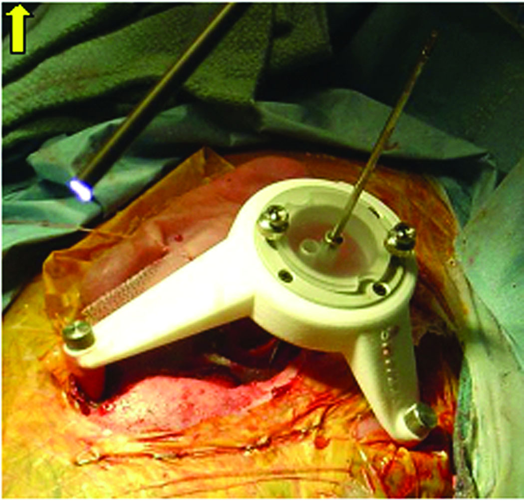
The limitation of the current embodiment of this technique is a delay between Steps 3 and 4. More specifically, once bone-implanted markers are placed and the CT scan is obtained, there is a requisite delay in construction of the micro-stereotactic frame while the current FDA-approved micro-stereotactic frame, the StarFix™ (FHC, Inc., Bowdoin, ME) (Figure 1) is fabricated at a centralized facility using rapid-prototyping technology. Ironically, to achieve the submillimetric level of accuracy necessary for this application, the “rapid”-prototyping machine requires hours to construct the customized micro-stereotactic frame. In addition, because the rapid-prototyping machine is expensive to purchase, a centralized facility offers an economic benefit. The minimum 48-hour delay is cumbersome for patients and surgeons.
Figure 1.
Customized StarFix™ micro-stereotactic frame mounted on bone-implanted markers for percutaneous cochlear implantation (PCI) validation.
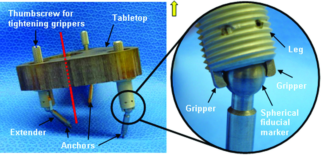
To overcome this limitation, we have developed a micro-stereotactic frame, which we call a “Microtable” that can be manufactured in less than five minutes. The engineering details of the microtable have been recently published [4]. As shown in Figure 2, this device consists of a tabletop that sits on three legs, the heights of which are adjustable by countersinking or recessing into the table top. The legs attach directly to the fiducial markers implanted into the skull of the patient via a sphere-and-gripper coupling (see magnified panel in Figure 2) such that attachment encompassing arbitrary orientations of the legs to the spheres is possible. By countersinking the legs into the tabletop, it is possible to make the plane of the tabletop perpendicular to the desired trajectory. Next, one need only specify the point of intersection of the trajectory with the surface of this tabletop in relationship to the legs. By countersinking the target hole, we set the trajectory distance from the top plane of the target hole to the target at 75 mm. By means of this technique, we have demonstrated in vitro targeting accuracy of 0.37 ± 0.18 mm [4]. This accuracy matches that of the StarFix™[5], and the microtable is much easier to construct because the only parameters that need to be specified are the x, y locations of each leg, the countersinking depth for each leg, and the x,y intersection of the trajectory with the tabletop. As a result, a microtable can be fabricated in less than five minutes on a standard computer-numeric-control (CNC) machine. From the standpoint of work flow, this design has revolutionized the procedure by reducing the delay between Steps 3 and 4 from days to minutes, thereby allowing clinical testing without encumbering either the patient or the surgeon. The report herein details the application of this technology to clinically testing of PCI.
Figure 2.
Microtable. Three spherical fiducial markers are attached to the patient via anchors. The tabletop is elevated above the spherical fiducial markers using legs that are countersunk to orient the tabletop perpendicularly to the trajectory (shown in red). Coupling mechanism between spherical fiducial marker and table leg is shown in the inset. Twisting the thumbscrew tightens the grippers, thereby fixing the leg to the marker.
MATERIALS AND METHODS
Institutional Review Board approval was obtained for the validation study, and all patients who participated in the study gave informed consent. Inclusion criteria consisted of patients who were scheduled for traditional cochlear implant surgery, between the ages of 18 and 80, and free of co-morbid conditions deemed in the judgment of the surgeon or the anesthesiologists to be significant enough that an extra ten to twenty minutes of operating room time for participation in the research would not jeopardize their health. Each patient enrolled had the following procedures performed:
Informed consent was obtained.
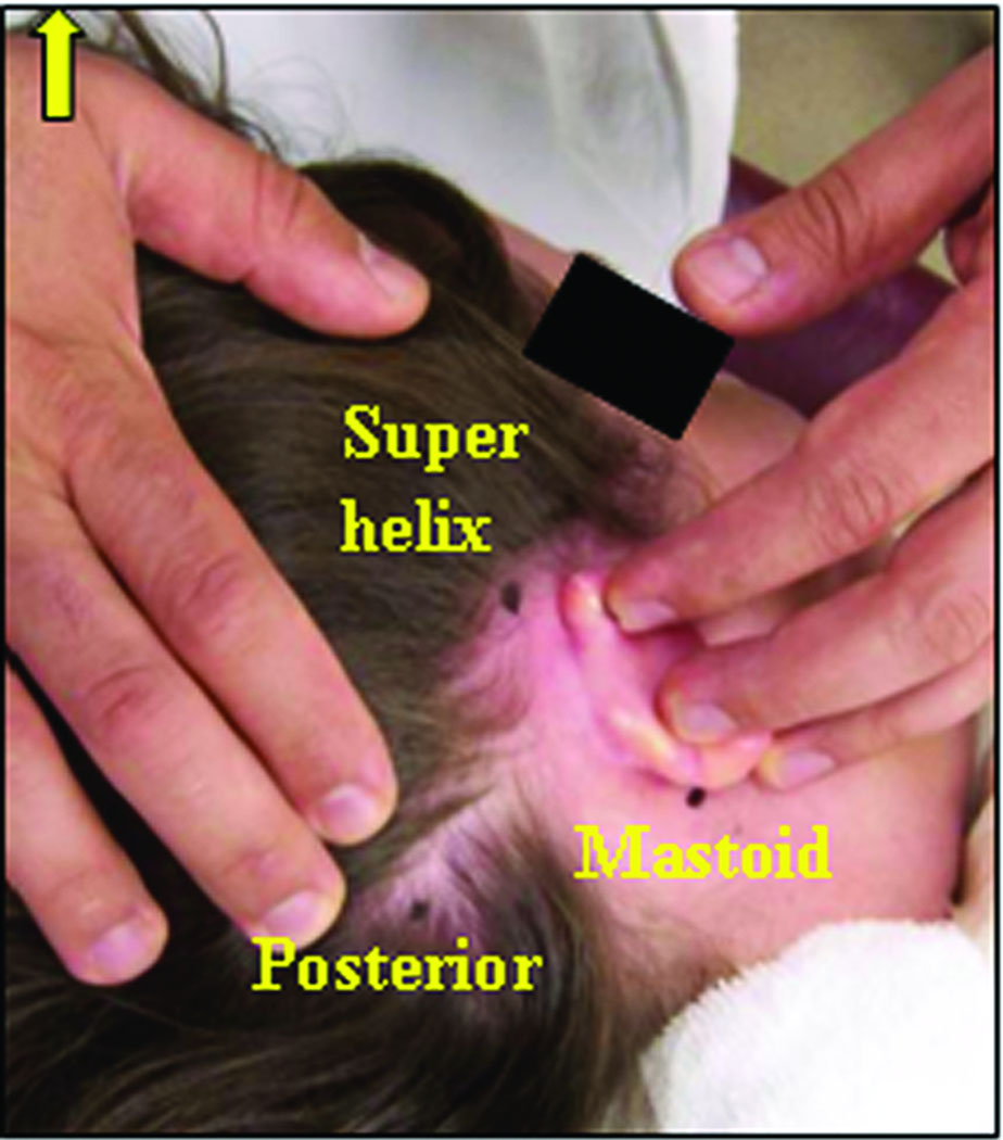
Bone-implanted fiducial markers were placed at three locations behind the ear – the mastoid tip, the supra-helical region, and posterior to the sigmoid sinus. These positions were chosen approximately surrounding the desired trajectory (Figure 3).
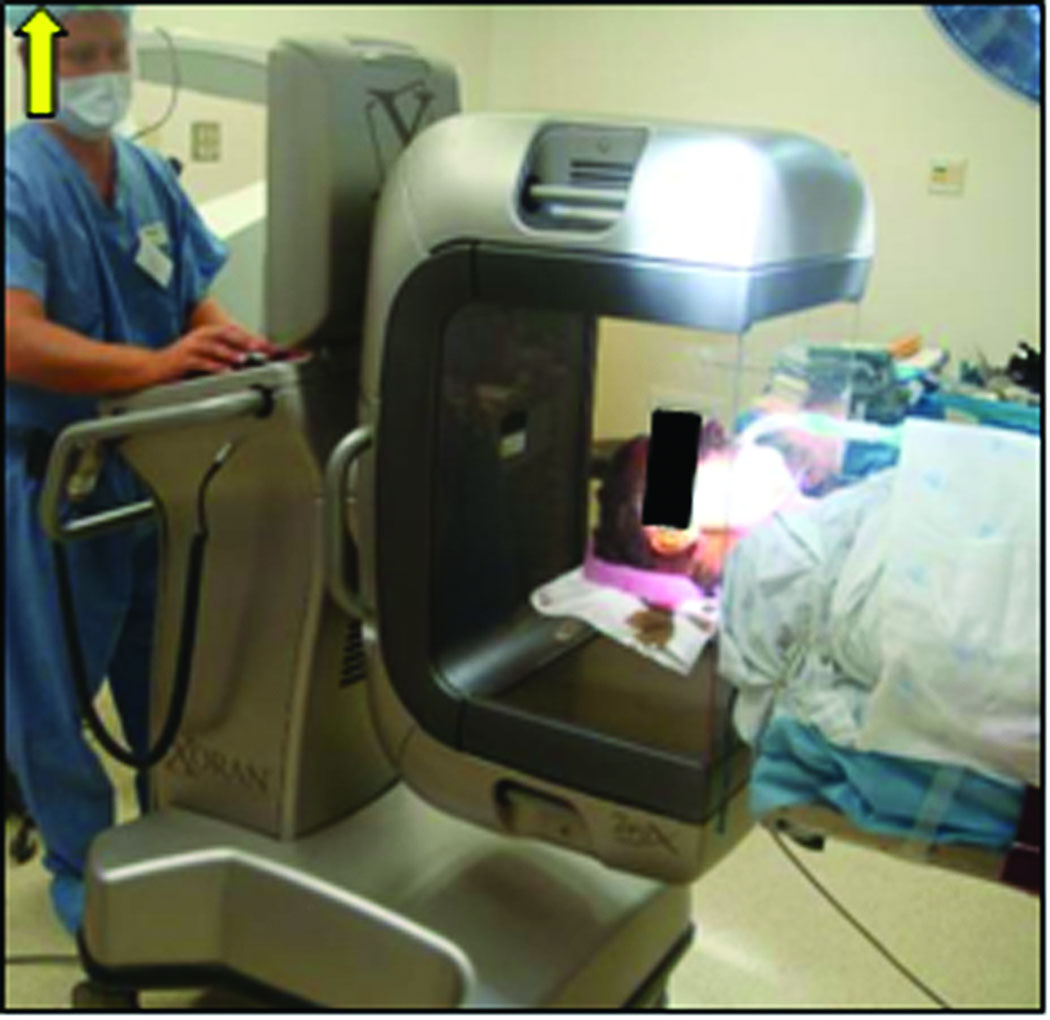
A clinically-applicable temporal bone CT scan was obtained, either in the outpatient setting (spiral cut CT scan with slice thickness of 0.8 mm and 0.4 mm overlap) or intra-operatively using a Xoran xCAT scanner (Xoran Technologies, Ann Arbor, MI) with voxel size of 0.3 mm isotropic (Figure 4).
By means of automated segmentation methods, the pertinent anatomy (facial nerve, chorda tympani, cochlea, labyrinth, ossicles, external auditory canal) were identified on the CT scan [6,7]. This process takes approximately six minutes, following which a trajectory that optimizes avoidance of the facial nerve and targeting of the scala tympani compartment of the cochlea is automatically determined [8]. This trajectory is verified by the surgeon. The centers of the markers are also localized in the CT scan.
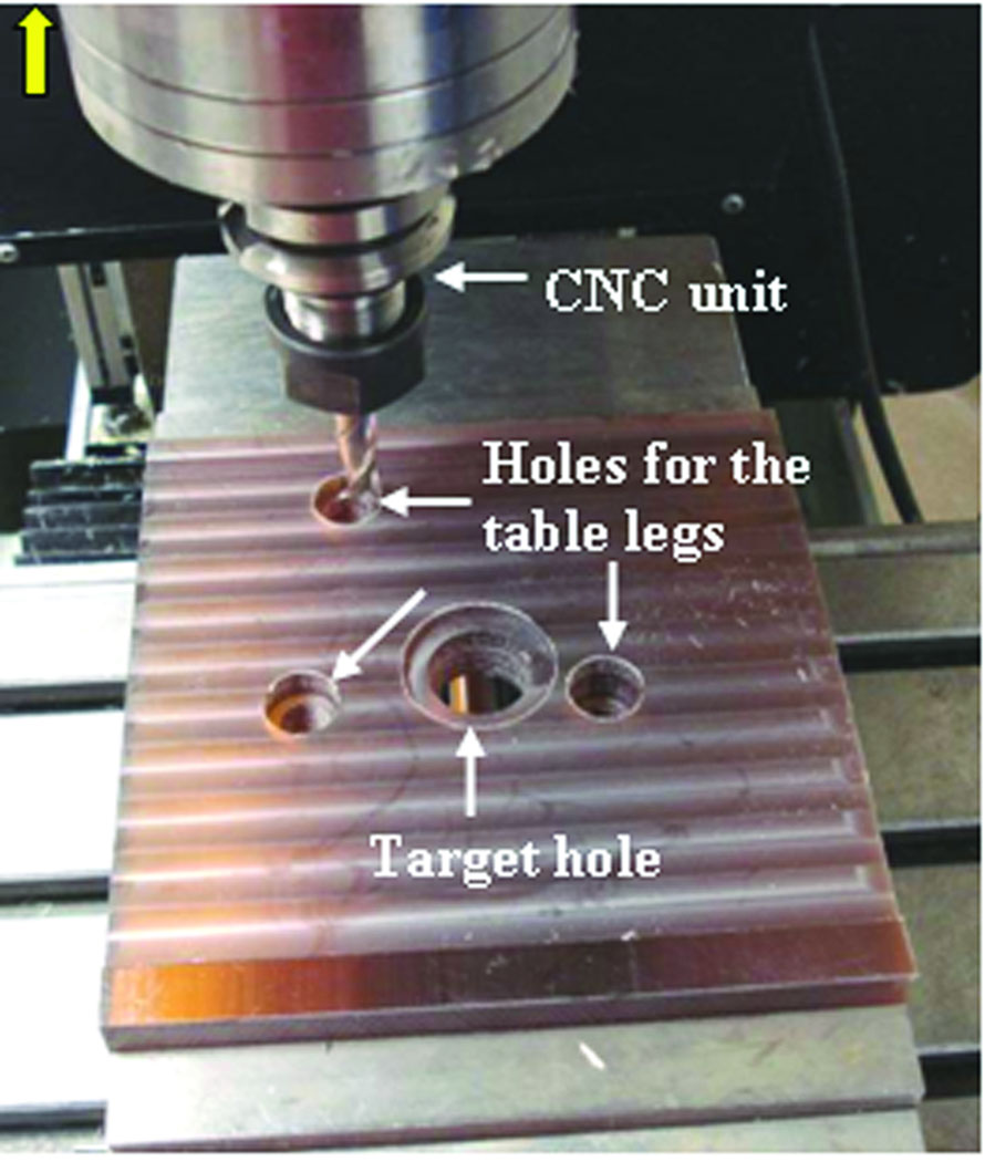
A customized microtable was produced on a CNC milling machine (Ameritech CNC, Broussard Enterprises, Inc., Santa Fe Springs, CA) from a blank of Ultem® (Quadrant Engineering Plastic Products, Reading, PA). Once the center target hole is machined, three holes are milled to the correct depths for the leg attachments (Figure 5). This process takes less than 5 minutes. The legs are then inserted into these holes completing the micro-stereotactic frame. Post-manufacturing quality control and attachment of coupling devices to join the legs to the microtable require an additional 2–3 minutes.
The microtable is transported to the operating room and sterilized.
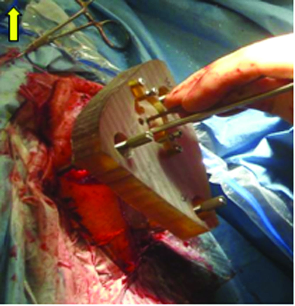
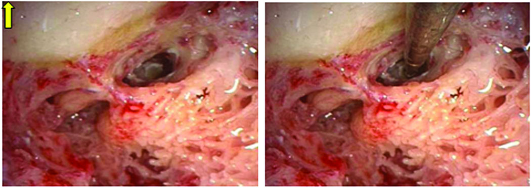
Validation of the trajectory is performed by affixing the microtable to the boneimplanted markers and passing sham drill bits of 1 mm and then 2 mm diameter, if there is clearance, through the already drilled mastoid and facial recess (Figure 6). Photo-documentation of the drill bit, as it lies in the plane defined by the facial nerve and chorda tympani, is then made (Figure 7). Photodocumentation was also made of where the sham drill bit would have produced a cochleostomy (Figure 8).
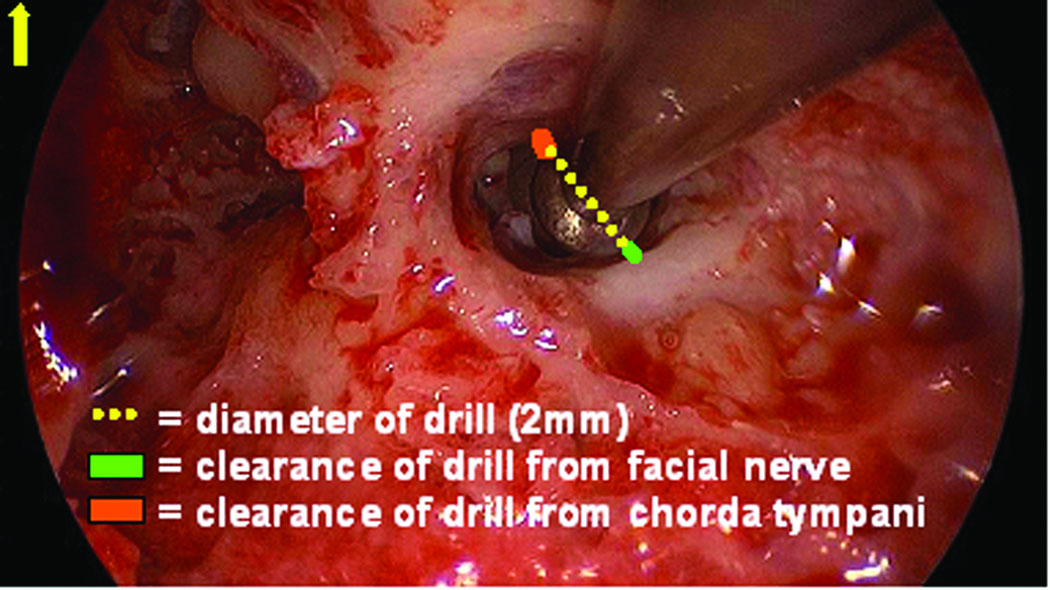
As shown in Figure 7, the digitized photograph is then measured, using the public-domain, digital-measurement program Image J (www.rsbweb.nih.giv/ij/). The measurement involves drawing a straight line at the widest portion of the drill bit to calibrate pixel size to physical size. Next, the closest distance from the drill bit to the bone covering the facial nerve and chorda tympani is measured and scaled. Of note, the jitter of the drill bit interface with the microtable as measured at the depth of the facial recess is 0.071 ± 0.03 mm.
Figure 3.
Approximate locations for the three bone-implanted markers.
Figure 4.
Intraoperative CT scan acquired using the Xoran xCAT flat-panel scanner after anchor implantation.
Figure 5.
Construction of microtable on computer-numeric-control (CNC) machine.
Figure 6.
Microtable mounted on the patient for PCI validation. Sham drill bit is passed in the center hole and endoscope used to photodocument trajectory.
Figure 7.
Measurement technique for estimating the distance from the centerline of the drill trajectory to facial nerve and chorda tympani. On the intraoperative endoscopic photograph a line is drawn over the drill bit, which provides a scale to the true physical size - 2 mm in this case. The distance from the edge of the drill to the chorda tympani and the facial nerve are then digitally drawn and calibrated.
Figure 8.
Location of Cochleostomy. Shown in Panel A is the cochleostomy site as selected by the surgeon by drilling off the round window overhang. Panel B shows the 1 mm sham drill bit targeting this location.
RESULTS
Eighteen microtables were constructed as per the methods described above. For all microtables, clinical validation was performed and the measurements from the mid-axis of the drill to the facial nerve and chorda tympani are presented in Table 1. Summarizing the results, mean distance ± standard deviation from the mid-portion of the drill to the facial nerve was 1.20 ± 0.36 mm and to the chorda tympani was 1.25 ± 0.33 mm. Note that measurements were made to the bone covering the facial nerve and chorda tympani, thus a small amount of clearance on top of the values reported in Table 1 exists. With this in mind, based on the results reported in Table 1, the success rate of passing a drill safely through the facial recess without impinging the facial nerve is 100% for a 1 mm drill, 94.44% (17/18) for a 1.5 mm drill, and 77.78% (14/18) for a 2 mm drill. Correspondingly, the success rate of passing a drill safely through the facial recess without impinging the chorda tympani is 94.44% (17/18) for a 1 mm drill, 94.44% (17/18) for a 1.5 mm drill, and 77.78% (14/18) for a 2 mm drill. On one ear (#3), the chorda tympani was hit by the drill – this was a planned hit as the patient had an extremely narrow facial recess appreciated on the pre-operative scan.
Table 1.
Distance in mm from axis of drill trajectory to facial nerve (FN) and chorda tympani (CT).
| Ear tested | Distance to FN | Distance to CT |
|---|---|---|
| 1 | 1.44 | 1.33 |
| 2 | 0.50 | 2.1 |
| 3 | 1.62 | - |
| 4 | 0.80 | 1.32 |
| 5 | 1.10 | 0.81 |
| 6 | 1.33 | 1.50 |
| 7 | 0.86 | 1.32 |
| 8 | 1.11 | 1.04 |
| 9 | 0.88 | 0.83 |
| 10 | 1.07 | 1.42 |
| 11 | 1.39 | 1.06 |
| 12 | 1.40 | 1.50 |
| 13 | 2.00 | 1.63 |
| 14 | 1.00 | 1.00 |
| 15 | 1.00 | 1.00 |
| 16 | 1.48 | 1.33 |
| 17 | 1.06 | 0.94 |
| 18 | 1.57 | 1.09 |
| Mean | 1.20 | 1.25 |
| Standard Deviation | 0.36 | 0.33 |
While location of the cochleostomy was difficult to objectively document in all cases, a representative targeting is shown in Figure 8. In this figure the surgeon-selected cochleostomy can be seen in panel A (at the site of drilling to remove the round window overhang) and the location of microtable-specified location in panel B. Subjectively, all targetings were loco typico for cochleostomy location.
DISCUSSION
We present herein a novel micro-stereotactic frame that can be used for accurate identification of intracranial targets, such as the cochlea. We also present clinical validation experiments, showing its accuracy as used for PCI validation. Our previous results indicate an in-vitro accuracy of 0.37 ± 0.18 mm [4]. During clinical validation experiments, we safely avoided vital anatomy and accurately targeted the cochlea. We have demonstrated that a 1mm drill bit can be passed through the facial recess in 18 of 18 cases without impingement to the facial nerve and with 1 injury to the chorda tympani. For larger drill bits the risk of damage is greater—the 1.5mm drill bit would have contacted 1 of the 18 facial nerves. However, the clearance of the drill bit through the facial recess is visualized during pre-operative planning (step 4 of the methods section) at which point, if concern exists regarding potential injury to the facial nerve, the trajectory can be modified shifting the risk of injury to the chorda tympani. For these validation experiments we did not modify any trajectories and thus have presented the worst case scenarios.
In prior work [3], we demonstrated the feasibility of PCI. However, to participating patients and surgeons, this process involved two stages: (1) placement of bone implanted anchors in clinic at least 48 hours prior to surgery and (2) clinical testing of the frame in the operating room during a traditional cochlear implant surgery. We sought a solution to make this process achievable in a single stage in an effort to make the process more user friendly for both patients and surgeons. The microtable offers one such solution as (a) it can be constructed on site by a skilled machinist in five minutes or less, and (b) it utilizes relatively standard machining equipment.
The microtable, in conjunction with intra-operative CT scanning, has allowed us to streamline our clinical testing of PCI by performing PCI validation experiments concurrently with traditional cochlear implant surgery. This approach proceeds as follows: Patients are prepped and draped as per routine cochlear implant surgery and a post auricular incision is made. Using this incision, markers are bone-implanted at the mastoid tip and the superior aspect of the post-auricular incision. Next, a posterior stab incision is made, creating an approximately equilateral triangle surrounding the mastoid. The patient is covered with a sterile plastic drape and the intra-operative CT scanner wheeled in to allow visualization of the markers and the temporal bone anatomy. Next, the surgeon performs traditional cochlear implant surgery, consisting of mastoidectomy and facial recess approach, while the anatomy is automatically identified and the PCI trajectory automatically computed from the CT scan. A short time later (less than 10 minutes), the program outputs a computer file that specifies the dimensions of the microtable. This file is sent electronically to a machine shop located in close proximity to the operating rooms, where it is read by the CNC machine and produces a customized tabletop of the microtable in less than five minutes. Once off the CNC machine, quality control is performed, and the rigid joints, which connect the microtable to the boneimplanted markers (i.e., ball and socket joints), are attached (Figure 2). Next, the microtable is transported to the operating room and sterilized. The entire process after CT scan is obtained until the microtable is delivered into the surgical suite is less than thirty minutes—less than the time it typically takes for a surgeon to perform a mastoidectomy and facial recess. As a result, participation in the research is invisible to the patient. This invisibility has promoted recruitment in our validation study.
While the microtable described herein has been clinically tested for access to cochlea, we envision other applications, including placement of deep brain stimulators in the subthalamic nucleus, access to the petrous apex for drainage of cholesterol granulomas, and access to the endolymphatic sac for treatment of Meniere’s disease. Application to each of these is a variant of the process described herein.
Acknowledgment
The project described was supported by Award Number R01DC008408 from the National Institute on Deafness and Other Communication Disorders. The content is solely the responsibility of the authors and does not necessarily represent the official views of the National Institute on Deafness and Other Communication Disorders or the National Institutes of Health.
Footnotes
Note: The authors have applied for multiple patents on this technology, some of which may lead to commercialization with the potential for financial benefit to them.
Contributor Information
Robert F. Labadie, Associate Professor of Otolaryngology-Head and Neck Surgery, Department of Otolaryngology-Head and Neck Surgery, Vanderbilt University Medical Center, 1215 21st Avenue South, MCE, Room 7209, Nashville, TN 37232, robert.labadie@vanderbilt.edu, Phone: 615-936-2493 Fax: 615-936-5515
Ramya Balachandran, Research Assistant Professor, Department of Otolaryngology, Vanderbilt University Medical Center, Nashville, TN, ramya.balachandran@vanderbilt.edu
Jason Mitchell, Research and Development Engineer, Department of Mechanical Engineering, Vanderbilt University, Nashville, TN, jason.e.mitchell@vanderbilt.edu
Jack H. Noble, Department of Electrical Engineering and Computer Science, Vanderbilt University, Nashville, TN, jack.h.noble@vanderbilt.edu
Omid Majdani, Department of Otolaryngology, Medical University of Hannover, Hannover, Germany, omid.majdani@gmx.de
David Haynes, Director, Division of Otology and Neurotology, The Otology Group of Vanderbilt, Vanderbilt University Medical Center, Nashville, TN, david.haynes@vanderbilt.edu
Marc Bennett, Assistant Professor, Department of Otology-Neurotology, Vanderbilt University Medical Center, Nashville, TN, marc.bennett@vanderbilt.edu
Benoit M. Dawant, Professor of Electrical Engineering and Computer Science, Department of Electrical Engineering and Computer Science, Vanderbilt University, Nashville, TN, benoit.dawant@vanderbilt.edu
J. Michael Fitzpatrick, Professor of Computer Science, Department of Electrical Engineering and Computer Science, Vanderbilt University, Nashville, TN, j.michael.fitzpatrick@vanderbilt.edu
REFERENCES
- 1.Labadie RF, Balachandran R, Fitzpatrick JM. Accuracy of Image-guided Surgical Systems at the Lateral Skull Base as Clinically Assessed Using Bone-Anchored Hearing Aid Posts as Surgical Targets. Otology and Neurotology. 2008 doi: 10.1097/MAO.0b013e3181859a08. [DOI] [PMC free article] [PubMed] [Google Scholar]
- 2.Warren FM, Balachandran R, Fitzpatrick JM, Labadie RF. Percutaneous Cochlear Access Using Bone-Mounted, Customized Drill Guides: Demonstration of Concept In-Vitro. Otology & Neurotology. 2007;28(3):325–329. doi: 10.1097/01.mao.0000253287.86737.2e. [DOI] [PubMed] [Google Scholar]
- 3.Labadie RF, Noble JH, Dawant BM, Majdani O, Balachandran R, Fitzpatrick JM. Clinical Validation of Percutaneous Cochlear Implant Surgery: Initial Report. Laryngoscope. 2008;118:1031–1039. doi: 10.1097/MLG.0b013e31816b309e. [DOI] [PMC free article] [PubMed] [Google Scholar]
- 4.Labadie RF, Mitchell J, Balachandran R, Fitzpatrick JM. Customized, Rapid Production Micro-stereotactic Table for Surgical Targeting: Description of Concept and In-vitro Validation. International Journal of Computer Assisted Radiology and Surgery. 2009 May;4(3):273–280. doi: 10.1007/s11548-009-0292-3. [DOI] [PMC free article] [PubMed] [Google Scholar]
- 5.Balachandran R, Mitchell J, Dawant B, Fitzpatrick JM. Evaluation of Targeting Frames for Deep-Brain Stimulation Using Virtual Targets. Presented at the Proc. IEEE Intl. Symp. On Biomedical Imaging 2007; Arlington, VA. 2007. Apr, pp. 1184–1187. [Google Scholar]
- 6.Noble JH, Warren FM, Labadie RF, Dawant BM. Automatic Segmentation of the Facial Nerve and Chorda Tympani in CT Images Using Spatially Dependent Feature Values. Medical Physics. 2008;35(12):5375–5384. doi: 10.1118/1.3005479. [DOI] [PMC free article] [PubMed] [Google Scholar]
- 7.Noble JH, Dawant BM, Warren RM, Majdani O, Labadie RF. Automatic Identification and 3-D Rendering of Temporal Bone Anatomy. Otology and Neurotology. 2009;30:436–442. doi: 10.1097/MAO.0b013e31819e61ed. [DOI] [PMC free article] [PubMed] [Google Scholar]
- 8.Noble JH, Warren FM, Labadie RF, Dawant BM, Fitzpatrick JM. Determination of drill paths for percutaneous cochlear access accounting for target positioning error. Proc. SPIE. 2007;6509:650925.1–650925.10. [Google Scholar]


