Abstract
We review efforts to produce microfabricated glucose sensors and closed loop insulin delivery systems. These devices function due to the swelling and shrinking of glucose-sensitive microgels that are incorporated into silicon-based microdevices. The glucose response of the hydrogel is due to incorporated phenylboronic acid (PBA) side chains. It is shown that in the presence of glucose, these polymers alter their swelling properties, either by ionization or by formation of glucose-mediated reversible crosslinks. Swelling pressures impinge on microdevice structures, leading either to a change in resonant frequency of a microcircuit, or valving action. Potential areas for future development and improvement are described. Finally, an asymmetric nano-microporous membrane, which may be integrated with the glucose sensitive devices, is described. This membrane, formed using photolithography and block polymer assembly techniques, can be functionalized to enhance its biocompatibility and solute size selectivity. The work described here features the interplay of design considerations at the supramolecular, nano, and micro scales.
Keywords: Hydrogels, swelling, glucose sensing, closed loop insulin delivery, microfabrication, block polymers, self assembly, microporous membrane, nanoporous membrane
Introduction
This paper reviews work on implantable glucose sensors and closed loop insulin delivery systems, based on swelling and deswelling of glucose sensitive hydrogels incorporated into devices whose features are engineered at the micro and nanoscales. A synergy between top-down and bottom-up approaches to device fabrication using hard and soft materials is proposed.
Hydrogels, i.e. crosslinked polymer networks that absorb water, are soft materials that are of great biomedical interest due to their favorable mechanical, mass transfer, and interfacial properties with biological tissues. The polymer network and the absorbed water contribute separately and synergistically to the hydrogel's properties. Most simply, the network is responsible for the hydrogel's elastic and shape preserving characteristics, while absorbed water accounts for the hydrogel's lubricity and also serves as the primary conduit for diffusion of solutes. Solute partitioning and permeability and hydrogel swelling equilibrium and kinetics are affected by interactions between the network and the absorbed water.
It has been convenient to describe swelling equilibria of hydrogels in terms of three forces, or contributions to free energy, that are typically assumed to be independent (Figure 1) [1-3]. The first force is due to entropy-driven mixing of water with the polymer, which is enhanced or reduced depending on the compatibility (contact free energy) of these two components. The second force is polymer elasticity, which is driven by polymer chain entropy. This force, which depends on the degree of crosslinking of the hydrogel network, opposes swelling and shrinking of the network away from the swelling state corresponding to the maximum number of polymer configurations. These two forces alone account for the swelling of electrically neutral hydrogels. Hydrogels containing ionizable side chains are also subject to a third, osmotic force, attributed to the accumulation of an excess of mobile ions inside compared to the external environment due to a Donnan potential [4,5] This third force usually promotes osmotic swelling of the hydrogel, although shrinking may also occur due to ionic bridging by multivalent counterions [5] or polyampholyte effects when both positive and negative fixed charges are present [6,7].
Figure 1.
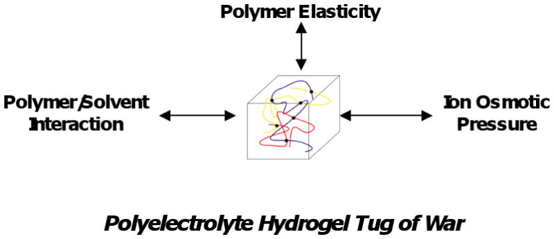
Schematic of forces influencing polyelectrolyte hydrogel swelling.
Of particular interest are stimuli sensitive hydogels, whose swelling depends on physical (e.g. temperature, light) and chemical (e.g. pH, ionic strength, glucose concentration) parameters of the surrounding environment. These stimuli may impinge on any of the three forces mentioned above. As examples, temperature may strongly affect solvent quality, pH may have a strong effect on ionization, and addition of specific solutes may lead to new, reversible crosslinks. With proper design of the hydrogel, swelling may change dramatically over a small range of external parameter variation. Discontinuous, first order volume phase transitions have been observed. Because of this sensitivity to external stimuli, such hydrogels have received considerable attention in recent decades as mediators for biosensing and modulated drug delivery [8-11].
In most studies of the effects of stimuli on hydrogels, the sample is exposed to a solution with defined physical and chemical parameters and free, unconstrained swelling is measured. Under this condition, swelling equilibrium corresponds to a cancellation of all swelling stresses inside the hydrogel. While free swelling is an excellent characterization tool, it is not necessarily the most relevant to sensing and drug delivery applications, especially when the hydrogel is implanted into a body space. Free swelling may be difficult to measure in vivo, and the benefit of free swelling controlled release from implanted hydrogels is probably limited to highly potent drugs or biological response modifiers.
Besides equilibrium properties, kinetics plays a prominent role in hydrogel applications. It is well known that swelling and shrinking kinetics of hydrogels is dominated by diffusional motion of solutes and of polymer chains against the solvent. Since diffusion time scales as the square of the hydrogel's smallest dimension, size will have a strong impact. Conventional hydrogels with dimensions measured in several millimeters to centimeters may require months to reach swelling equilibrium. Noting that each tenfold reduction in size leads to a potential hundredfold reduction in equilibration time, it becomes apparent that rapidly (say ∼10 min) responding hydrogels should have dimensions on the order of tens of microns.
Finally, most conventional stimuli sensitive hydrogels are mechanically weak and prone to fracture due to inhomogeneities, which serve as crack initiation points. While several strategies to improve hydrogel toughness have been introduced [12-16], they tend to involve specialized chemistries that are not easily generalized.
To remedy some of the disadvantages associated with free hydrogel swelling, we have been investigating hydrogels that are embedded in microfabricated hard and/or soft structures that limit swelling and shrinking. The hydrogel exerts forces on the restricting structures, and these forces produce transduction. Juxtaposition of a responsive material with a solid structure is a common theme in biology—one need only recognize that contraction of muscle is converted to useful, directed motion by bone. Furthermore, embedding hydrogels in hard and soft supporting materials confers addressability, and future applications may involve coordinated action of numerous small hydrogels embedded in the same device.
Microfabricated hydrogel based devices that are responsive to glucose are being developed in our laboratory. These devices exploit the glucose-dependent swelling behavior of phenylboronic acid (PBA) derivatives. The most promising device at present is a passive implantable microsensor which, following implantation, can be interrogated by wireless means, obviating the need for batteries and lead wires that breach the cutaneous barrier. A related device, a glucose-sensitive microvalve which modulates fluid flow, e.g. of an insulin solution, is also described. Both devices rely on selective exchange of small solutes such as water, glucose, and small electrolytes within the physiologic environment, and thin, strong, size selective membranes, which also may serve as interfaces with the host tissue, will be important for biointegration.
Following a discussion of PBA-based hydrogels and the two microfabricated devices, we will review the development of an asymmetric membrane in which a microporous supporting silicon structure is coated by a transport selective nanoporous block polymer membrane. Taken together, this work illustrates a combination of top-down micromachining and bottom-up nanoassembly. Details regarding methods are available in referenced publications.
Hydrogel Structure and Response
Early work on glucose sensitivity mediated through hydrogel swelling involved the combination of glucose oxidase, which converts glucose to gluconic acid, with a pH sensitive hydrogel containing acid groups such as alkylacrylic acids, or basic groups such as N,N,dialkylaminoethyl methacrylates or methacrylamides [17-20]. This approach suffers from glucose oxidase's tendency to degrade over time and the presence of physiologic buffers that attenuate pH response [21-23].
More recently, hydrogels containing phenylboronic acids (PBA's) have received considerable attention [24-37]. As shown in Figure 2, the trigonal PBA moiety is a Lewis acid whose unfilled sp2 electron orbitals can be receptors for Lewis bases. For example, hydroxide ion (OH-) binds to polymerized methacrylamidophenylboronic acid (MPBA) with pKa≈8.86, converting it to tetrahedral methacrylamidophenylboronate ion (MPBA-). The charged tetrahedral boronate is in a favorable configuration to undergo bidentate condensation with diols such as glucose. Thus glucose stabilizes the charged form of MPBA, promoting development of Donnan osmotic swelling forces. (We neglect a weak but measureable binding of glucose to trigonal MPBA [26,27,35,36].) Several groups have exploited this property for hydrogel-based sensing and delivery. Asher et al have incorporated colloidal crystal arrays inside hydrogels containing MPBA and acrylamide (AAm), and were able to detect changes in glucose concentration by a shift in optical diffraction wavelength [26-28]. Related holographic techniques have been explored [31-33]. Kataoka et al. demonstrated glucose-sensitive insulin permeability changes in MPBA containing membranes [24,25].
Figure 2.
Conversion of trigonal (Lewis acid) form of phenylboronic acid moiety to the tetrahedral (Lewis base) form in the presence of OH-, followed by bidentate condensation of cis-diol bearing ligands (sugars in the present case). Not shown is a relatively unimportant pathway in which sugar binds first to trigonal form. After Kataoka et al. [25].
We have studied the pH- and glucose-sensitive free swelling properties of a poly(MPBA-co-AAm) hydrogel, crosslinked with methylene bisacrylamide (Bis). AAm monomer was included because MPBA is intrinsically hydrophobic, and pure MPBA hydrogels respond very slowly to changes in glucose concentration. Details regarding hydrogel synthesis and swelling measurements are in Appendix I. Briefly, hydrogels with 0-20 mol% MPBA substitution into pAAm were synthesized in aqueous solution in cylindrical (0.8 mm ID) capillaries. Following removal from the capillaries and extraction of unreacted components and sol fraction, the hydrogels were exposed to buffered solutions (ionic strength 155 mM) of varying pH and glucose concentrations and swollen to equilibrium.
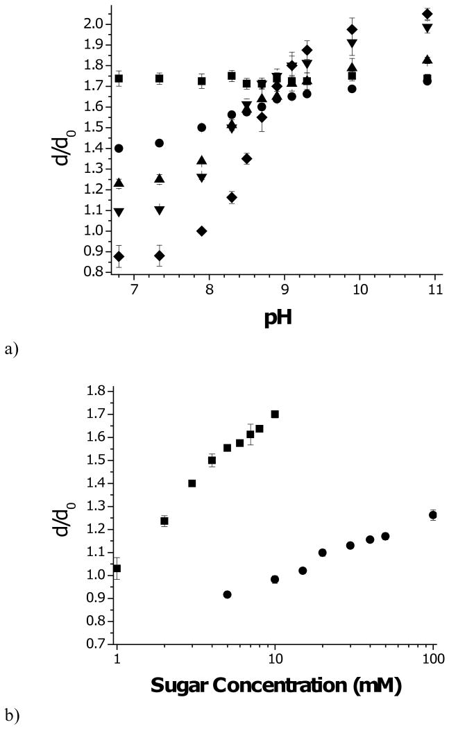
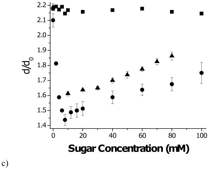
Figure 3a displays the equilibrium swelling response of the various poly(MPBA-co-AAm) hydrogels to sugar free solutions as a function of pH. Swelling is reported as the ratio of the hydrogel diameter, d, under a given condition, and the diameter at synthesis, d0=0.8 mm. As expected, hydrogels containing AAm alone do not respond to change in pH. Incorporating MPBA into the hydrogel leads to pH sensitivity. Below pH 9, which is close to the pKa of MPBA, increased MPBA content led to reduced swelling, while above pH 9, increased MPBA leads to increased swelling. These phenomena are explained by the hydrophobic nature of MPBA when it is uncharged, and an increase in polarity and Donnan potential as it charges with increasing pH. Because the 20% composition was most sensitive, this hydrogel was used in subsequent studies.
Figure 3.
Swelling (dilation factor with respect to diameter at synthesis) of p(MPBA-co-AAM) hydrogels.
a) Effect of pH on swelling for hydrogels with following mol% PBA in polymer: (■) 0%; (●) 5%; (▲) 10%; (▼) 15%; (◆) 20%.
b) Effect of sugar concentration at pH 7.4: (■) fructose; (●) glucose.
c) Effect of sugar concentration at pH 10.0: (■) fructose; (●) glucose; (▲) glucose+0.2mM fructose.
Error bars are standard deviations.
Free swelling measurements of the glucose sensitive hydrogel, carried out at pH 7.4 in PBS are presented in Figure 3b. Swelling increases monotonically with increasing glucose concentration due to progressive ionization, in line with the scheme in Fig. 2. Also shown in Fig. 3b are swelling data for the same hydrogels in similar media, but with fructose substituted for glucose. For clarity, sugar concentrations are plotted on a log axis. Evidently, these hydrogels are much more sensitive to fructose than glucose, as might be expected based on the two sugars' relative dissociation constants to tetrahedral PBA-, Kf=0.27 mM and Kg=9 mM, respectively [37].
Based on the glucose sensitive ionization scheme of Figure 2, the fraction of ionized PBA moieties in the hydrogel at equilibrium is modeled by
| (1) |
where Cs is the external sugar concentration (s=f or g), Ks is the dissociation constant of the sugar molecule to MPBA-, and λ is the Donnan ratio, which is the ratio of concentrations of individual univalent positive ions (e.g. Na+, H+) in the hydrogel's interstitial fluid to their respective concentrations in the external medium. For anionic hydrogels, λ>1. The Donnan ratio is calculated according to the electroneutrality condition
| (2) |
where φ is the volume fraction of polymer, φ0 is the polymer volume fraction at synthesis gelation, σ0 is the molar concentration of ionizable groups at in the aqueous synthetic mixture, and zi, are respectively the valence and concentration (mol/L) of the i'th mobile ionic species in the external aqueous medium. For isotropic swelling, φ / φ0 = (d0 / d)3. The ideal Donnan swelling pressure, modeled assuming negligible interaction between charges except for those needed to maintain overall electroneutrality, is calculated using the Donnan relation , where ci is the ion concentration in the hydrogel water, and van't Hoff's law,
| (3) |
where R is the gas constant and T is temperature (°K) [3,4,38].
When the medium consists primarily of a 1-1 electrolyte such as NaCl with concentration , Eqs. (2) and (3) are simplified by defining the dimensionless parameters and λ1/2 = 10pH–pKa (1 + cg / Kg) [39]. Algebraic rearrangements reveal the dimensionless relations
| (4) |
and
| (5) |
Since λ1/2 >0 and θ>0, the LHS and RHS of Eq. (5) decrease and increase monotonically, and we deduce that only one real root, λ >1, exists. Furthermore, λ increases with increasing θ and with increasing λ1/2. Equation (4) indicates that at constant salt concentration and temperature, the ion swelling pressure increases with increasing λ. Taken together, the model predicts increasing Δpion with increasing pH or glucose concentration.
At free swelling equilibrium, Δpion is balanced by the polymer network's (negative) swelling pressure, Δpnet, due to polymer/solvent mixing and polymer elasticity. A useful model for the network swelling pressure is the extended Flory-Rehner theory, according to which [1,3,26]
| (6) |
where χ is the polymer/solvent interaction parameter, νw is the molar volume of water (0.018 cm3/mol), and ρ0 is the molar concentration of polymer chains contributing to network elasticity (roughly proportional to the concentration of crosslinks) when the hydrogel is synthesized. The χ parameter is expected to increase with increasing MPBA content due to intrinsic hydrophobicity of MBPA, but it might decrease when MPBA is ionized, due to increased ion-dipole interactions with water.
To predict free swelling equilibrium, we add Eqs. (4) and (6) and set the total swelling pressure Δpsw = Δpion + Δpnet = 0, subject to Eq. (5). The unknowns φ, α, and λ are calculated simultaneously, and the swelling ratio relative to the reference state, φ0 / φ, is determined.
We shall not attempt here to carry out the model fitting procedure. Instead we call attention to a qualitative feature that can be tested directly against the data. Under the assumptions of the model, the only effect sugar molecules have on swelling is through stabilization of the ionized, tetrahedral form of MPBA, as quantitated through the parameter α. It follows, according to Eq. (1), that for any value of α [and hence φ, determined by Eqs. (1)-(5)],Cf / Kf = Cg / Kg, or log10 Cg −log10 Cf = log10 (Kg / Kf), so the glucose and fructose curves should be translates of each other along the log-transformed abscissa. It is evident from Figure 3b that this is not the case. The swelling curve for fructose is steeper than that for glucose. One possible explanation is that glucose and fructose binding differentially alter the hydrogel's hydrophobicity, i.e. the χ parameter. Other data, to be discussed in the following paragraphs, argue for a different mechanism.
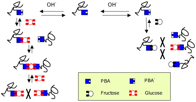
In Figure 3c, swelling is plotted versus concentration in the presence of fructose, glucose, and a combination of the two sugars, at pH 10. At this pH, a strong majority of the MPBA units are ionized, so swelling should not change greatly as a result of sugar binding. This is seen to be the case when the hydrogel swells in fructose. Glucose, on the other hand, causes the hydrogel to shrink at low concentrations. A swelling minimum is observed near Cg=9mM, followed reswelling at higher glucose concentrations. In the presence of 0.2mM fructose, this shrink/reswell behavior is attenuated. Similar results that have been reported by other laboratories [27,31]. The general consensus is that glucose is able to form bisbidentate complexes with PBA groups residing on different polymer chains, leading to reversible covalent crosslinks by virtue of the presence of two cis-diol pairs on glucose. These glucose mediated crosslinks are in addition to the permanent crosslinks formed during polymerization. Fructose, having only one cis-diol, cannot form such crosslinks and inhibits glucose-mediated crosslink formation. With increasing glucose concentration, new crosslinks form, causing the hydrogel to contract until the point is reached where free glucose competes with crosslinking glucose to form monobidentate complexes with PBA. At this point, the hydrogel reswells. This general mechanism is illustrated in Figure 4.
Figure 4.
Interactions of glucose and fructose with PBA units. A single glucose molecule can bind to one (monobidentate) or two (bisbidentate) PBA units at low and intermediate concentrations. Bisbidentate interactions lead to reversible crosslinks between polymer chains. At higher concentrations free glucose competes with bisbidentate glucose for PBA sites, reducing bisbidentate interactions. Fructose is only capable of monobidentate binding, and it inhibits bisbidentate crosslink formation.
Further evidence for glucose-mediated crosslinking is inferred from mechanical studies. Cylindrical disk hydrogels were placed between two platens, and a rapid (4 sec) linear compression ramp was applied. The slope of the force versus displacement curve was used to calculate shear modulus, taking into account the surface area and thickness of the hydrogel disk. According to Flory-Rehner and many scaling theories [1,40], the ratio of shear moduli of a gel at two degrees of swelling but with the same number of crosslinks is given by
| (7) |
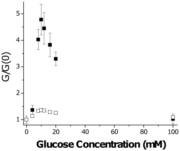
This idea is tested in Figure 5, where we take “1” to correspond to the sugar-free condition and “2” to denote a hydrogel swollen to equilibrium at a given sugar concentration, i.e. G / G(0) = d(0) / d. While the prediction of Eq. (7) is roughly correct for fructose and at high glucose concentrations, shear modulus greatly exceeds that predicted over the glucose concentration range where shrinking is observed (see Fig. 3c). Extra crosslinks must be contributing to the short term shear modulus over this range. Note that there is no increase in shear modulus at 100 mM glucose, where all PBA sites are occupied by monobidentate glucose.
Figure 5.
Shear modulus of 20% MPBA hydrogel as function of glucose concentration at pH 10. Values are normalized by shear modulus of pH 10 solutions with no glucose added. (■) observed; (□) predicted based on data of Fig. 3c and assuming no change in crosslink density, i.e. G / G(0) = d(0) / d. Error bars are standard deviations.
Since the glucose-mediated crosslinks are formed by a reversible reaction, individual crosslinks are not permanent, but are constantly forming and breaking. These processes, which are accompanied by chain rearrangements, can be observed in dynamic mechanical studies [41], the results of which will be reported elsewhere.
We believe that the observations of shrinkage at pH 10.0 can be used to explain the nonconformal swelling curves for fructose and glucose at physiological pH. The course of swelling as a function of fructose concentration can be completely explained by monobidentate binding to MPBA, with progressive charging of the hydrogel. At low glucose concentrations, initial binding is similarly monobidentate, but as glucose concentration is increased, some of the binding is bisbidentate, leading to enhanced crosslinking even as the network charge is increasing. The combination of these two effects leads to attenuated swelling in glucose compared to fructose, even after their respective binding constants are taken into account.
The shrinking mode observed in Figure 4 may be useful in sensing or valving, provided it can be translated to pH 7.4. Efforts toward shifting pH response in the acidic direction have been reported by several groups, either by derivatizing MPBA with electron-withdrawing groups that lower pKa [29,42], or by copolymerizing amines with MPBA [31,41,43]. The amines serve as electron donors to the sp2 shell of the boronic acid, and therefore replace OH- as the Lewis base. This approach may substantially reduce pH-dependence of hydrogel swelling, which is of concern since diabetics are prone to acidotic and alkalotic swings in blood pH. To analyze the significance of pH-sensitivity when swelling is determined exclusively by network ionization, we observe in Eq. (5) that the fraction ionized parameter, α, depends only on λ1/2 since λ is calculated in the process of determining swelling. We consider how λ1/2 varies differentially with Cg and pH, and find
| (8) |
When Δλ1/2 = 0, ΔCg = −2.3(Kg + Cg)ΔpH, indicating that over typical blood glucose ranges, say Cg=5-120 mM, an acid shift of 0.1 pH unit would produce the same effect on hydrogel swelling as a 3.2-6.7 mM increase in blood glucose concentration. This effect, which does not depend on the pKa of the PBA moiety, must be compensated or eliminated in any practical glucose-sensitive sensor or actuator whose mechanism is based on ionization. Compensation may be achieved either by removing the need for OH- in the Lewis acid-base reaction, perhaps by inclusion of amines or other Lewis bases in the hydrogel, or by introducing a second hydrogel that monitors pH alone. These considerations become much less important when glucose crosslink-mediated shrinking is the dominant mechanism, especially when this occurs with negligible dependence of α on glucose concentration [28].
It was previously noted that fructose has a much higher affinity for MPBA than glucose. However, the typical blood concentration of fructose is reported to be <20 μM [44], well below Kf=0.23 mM, so its fluctuations appear to be insignificant compared to those of glucose or pH.
While the free swelling measurements are easy to carry out and permit useful information about hydrogel response to be obtained, they are not directly predictive of the response of a confined hydrogel. In the sensor to be described below, the hydrogel is confined in a rigid cavity, and its response is essentially isochoric [45,46], i.e. its volume and geometry do not change significantly with glucose concentration. In this case Δpsw = Δpion + Δpnet > 0, provided the hydrogel does not shrink below the volume of the confining cavity. The latter condition should be a requirement for practical devices. Swelling pressure Δpsw is matched at equilibrium by the mechanical stresses at cavity boundaries, which are measured by strain or displacement detection.
In modeling the equilibrium isochoric swelling pressure, Eqs (4)-(6) still apply, with φ taken as constant, not necessarily equal to φ0. In the simplest conception, glucose affects swelling pressure only through Δpion via the parameter h. However, since ionization of the hydrophobic MPBA residue may affect χ, and since glucose can mediate extra crosslink formation between MPBA, Δpnet may also be glucose sensitive.
The isochoric scenario is idealized, insofar as some distortion of the cavity by the hydrogel is needed for detection or valving purposes. Swelling in a confined but deformable surrounding may lead to small shape changes, shear stresses may develop, and the parameters φ, α, and λ may become nonuniform even at equilibrium. If it can be assumed that these effects are minimal, then the simple uniform swelling model presented here will be useful in designing devices.
Implantable Glucose Microsensor [39,47]
To convert the glucose-sensitive swelling pressure developed in an MPBA-based hydrogel into a measurable signal that can be detected wirelessly, the hydrogel was embedded in a small silicon-based capacitive sensor, shown schematically in Figure 6a. The hydrogel was introduced between a rigid, porous aluminum oxide membrane (Anopore®: 0.25 porosity, 60 μm thick) and a more compliant glass diaphragm (pyrex, 30 μm thick). The diaphragm was formed by chemically etching a pyrex wafer on both sides, forming cavities of thickness 200 μm for the hydrogel and 20 μm for the capacitor gap, respectively. Glass facing the 20 μm cavity was sputter coated with 0.5 μm of Cr and Au under a finger-like pattern mask, forming the top plate of a microcapacitor. The bottom capacitor plate was a Cr/Au film coated on a silicon substrate, which also hosted a microinductor coil formed by deep reactive ion etching and filling with copper. Electrical contacts were established between the microcapacitor plates and the microinductor, forming a microresonator circuit. The glass and silicon members were anodically bonded, leading to a hermetically sealed capacitor gap. Pregel solution (20 mol% MPBA in polymer) was introduced into the 200 μm cavity in the pyrex, and covered with a silanized cover slip. Following polymerization, the Anopore® membrane was bonded onto the glass, sealing in the hydrogel.
Figure 6.
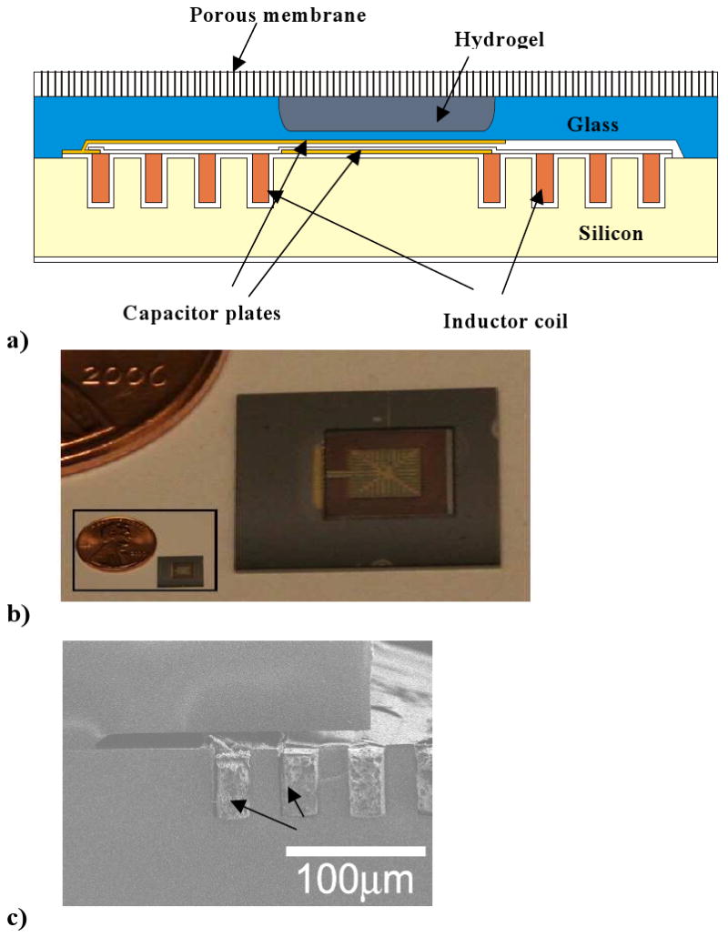
a) Schematic of integrated implantable glucose sensor featuring a glucose-sensitive hydrogel sandwiched between a rigid nanoporous membrane and a semiflexible micrcapacitor, which is connected to a microinductor coil.
b) Top view of microsensor indicating size. Microcapacitor in center is scored with cutting lines to reduce eddy currents, and from top vantage point appears to be “framed” by microinductor coil.
c) Side view of microcoil, which is deposited into trenches in bottom silicon piece. Panels a,c reproduced from Ref. 45 with permission.
Panel b reproduced from Ref. 39 with permission.
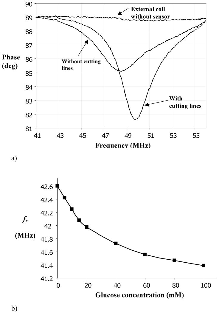
Micrographs showing a top view of the microcapacitor and a side view of the microinductor are provided in Figures 6b,c, respectively. The patterned Cr/Au deposition on the top microcapacitor plate reduced eddy currents, substantially sharpening the frequency response, as shown in Figure 7a.
Figure 7.
a) Example of frequency response (impedance) of LC microresonator, highlighting sharper resonance when cutting lines are included in microcapacitor.
b) Resonant frequency, (fr), of microsensor as a function of external glucose concentration in pH 7.4 PBS, at equilibrium.
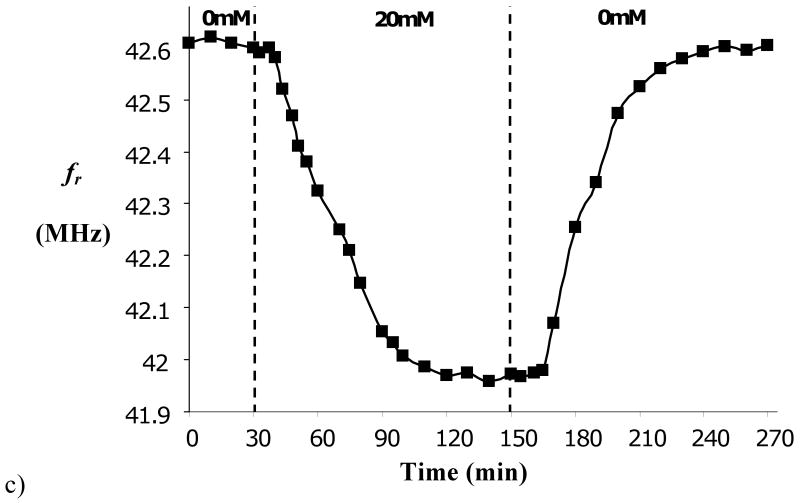
c) Kinetics of response of microdevice to changes in external glucose concentration. Panel a reproduced from Ref. 39 with permission. Panels b,c reproduced from Ref. 45 with permission.
The natural, or resonant frequency (Hz or cps) of the microresonator is given by
| (9) |
where L and C are the inductance (henry) and capacitance (farad) of the corresponding microcircuit elements. While L is fixed in the present circuit, C depends on the gap between the capacitor plates, which is in turn affected by the swelling pressure exerted by the hydrogel. By this means, changes in external glucose concentration are converted to changes in resonant frequency, which can be monitored by a remote radio frequency interrogating circuit. This microdevice is totally implantable, and requires neither its own battery nor transcutaneous wires.
Calculating the deformation of the diaphragm and resulting change in capacitance under a swelling hydrogel is difficult, and numerical techniques are generally required. When deformation is relatively small, then linear deformation laws will be obeyed. For a square diaphragm of width a and thickness t, and a gap g0 between the plates at zero swelling pressure, the fractional change in capacitance is approximated in the linear region by (see Appendix II)
| (10) |
where P0 is the air pressure in the unloaded cavity, AC and AH are the areas of the capacitor and the plates bounding the hermetically sealed cavity, respectively, and [48]
| (11) |
In Eqs. (10) and (11), C0 = εAC / g0 is the unloaded capacitance, where ε is the dielectric permittivity of air, while E and ν are the Young's modulus (Pa) and Poisson ratio, respectively, of the diaphragm. The denominator in the RHS of Eq. (10) accounts for the compressibility of air in the capacitor gap. To convert these relationships to fractional change in resonant frequency, expand Eq. (8) in fr around its unloaded value, f0, and assume small changes. The result is Δfr / f0 = −ΔC / 2C0.
Evidently, greatest sensitivity occurs when the diaphragm is wide and thin, and when the gap is narrow. While the range of pressures over which small deformation analysis applies is limited, these conclusions are expected to hold outside that range. Geometric parameters for the sensor components should be chosen to maximize sensitivity while minimizing the possibility of mechanical failure of the diaphragm.
A microsensor was fabricated with following parameters: a=2.42×103 μm, AC=(2.76×103 μm)2, AH=(3×103 μm)2, h=30 μm, g0=20 μm, and L=2.82 μH. The cavity containing the hydrogel was of thickness 200 μm. Taking the dielectric permittivity of air to be essentially equal to that in vacuum, ε=ε0=8.85×10⁻¹² coul2/(N-m2), the unloaded capacitance is estimated as 3.37 pF, and the unloaded resonant frequency is predicted to be 51.6 MHz. The latter was measured in the microsensor and was found to be about 51.2 MHz. The slight disparity is due primarily to stray capacitance between turns in the microinductor, although uncertainties in the geometric parameters may also play a role.
Using the tabulated values E=6.4×10¹⁰ GPa and ν =0.20 for pyrex, and P0=1 atm=1.103×10⁵ Pa, we calculate κ=7.1×10⁻⁵ Pa-1 and κ(AC / AH)2 P0 = 7.84. Evidently, air compression in the gap contributes significantly to reactance to deformation of the diaphragm by the expanding hydrogel. Based on these substitutions, Eq. (10) becomes ΔC / C0 = 2.04×10⁻⁴Δpsw(Pa) = 22.5Δpsw(atm).
The hydrogel-loaded microsensor was exposed to various glucose concentrations in pH 7.4 PBS, and its resonant frequency was determined by connecting it to a frequency analyzer and measuring the frequency of maximum phase dip in driving point impedance. As shown in Figure 7b, a rather well defined relationship between fr and Cg exists at equilibrium. At low glucose concentrations the frequency shift is nearly linear, but its slope falls off at higher glucose concentrations, which might be anticipated by the free swelling behavior shown in Fig. 3b. (The resonant frequency has been shown to shift linearly with applied air pressure [47].) Also, the resonant frequency of the device at zero glucose concentration is 42.6 MHz, which is 17% lower than that measured without the hydrogel. This disparity is attributed to a resting swelling pressure developed by the confined hydrogel after it is synthesized and equilibrated with external buffer. The frequency offset is larger than the range of frequencies corresponding to changes in glucose concentration, and in future design it should be minimized since it may be a source of interdevice variability and intradevice drift. Moreover, the large frequency offset suggests that deformation of the glass diaphragm may be out of its linear range, and the analysis leading to Eq. (10) may not be valid. On the other hand, the small operating range of resonant frequencies as a function of glucose concentration suggests that linearized analysis of diaphragm response around its resting value is possible, and that swelling is essentially isochoric.
To further characterize the sensor's utility, response kinetics were measured. As shown in Figure 7c, the sensor requires about 80 min to reach equilibrium, and there is a dead time of about 5 min following change in glucose concentration. These delays are not acceptable for treatment of diabetes, which requires ∼5 min response time. Response time can be substantially reduced by using a thinner hydrogel and a thinner rigid membrane. Based on theories of membrane transport hydrogel swelling kinetics, it is expected that response time will scale quadratically with thickness of these structures, but this scaling law may not hold when either binding/unbinding of glucose to the hydrogel, or the accompanying mechanical relaxations which occur when glucose-mediated crosslinking is an important factor, become rate limiting [41]. Faster response may also result by reducing the density of MPBA groups in the hydrogel, since this density determines the number of glucose molecules that must enter or exit the hydrogel to establish a new equilibrium state. However, both of these modifications will carry the cost of reduced sensitivity. Thinning of the solid structures must occur without sacrificing their mechanical strength.
Glucose Sensitive Microvalve [30,49]
While an implantable glucose sensor as described above would be an extremely useful adjunct to insulin therapy, it only goes half way to achieving the “holy grail” of closed loop control [50-52]. In present applications, the role of the sensor is to provide information either directly to the patient, or to an automated insulin delivery system such as a pump. Here we briefly comment on an extension of the sensor concept that could, in principle, provide closed-loop feedback control of insulin delivery.
Figure 8a diagrams the modified system. Again, the glucose-sensitive hydrogel (20 mol% PBA as above) is sandwiched between a rigid porous membrane and a diaphragm. However, the diaphragm now consists of flexible polydimethylsiloxane (PDMS), whose deformation opens and shuts a flow channel, acting as a valve. A silicon embossment is bonded to the diaphragm to increase efficiency of opening/shutting action. This assembly can be attached via a catheter to a pressurized insulin solution, e.g. in a small capsule which could be worn externally and replaced regularly. Obviously, the driving pressure must be less than the swelling pressure that is developed in the hydrogel during the shut phase.
Figure 8.
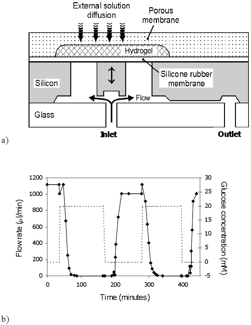
a) Schematic of microvalve which opens and shuts due to swelling and shrinking of glucose sensitive hydrogel.
b) Flow response of microvalve connected via tubing to a water column, with valve switched between PBS (pH 7.4) solutions containing 0 mM and 20 mM glucose.
Panel a adapted and panel b reproduced from Ref. 30 with permission.
Figure 8b displays the dynamic flow response of this microvalve when exposed to alternating 0 mM and 20 mM glucose solutions (PBS), with flow driven by a water column. Under these two conditions, the valve is open and shut, respectively, as indicated by the steady state flow values. In this case, the response lag is about 20 min, and there is a noticeable dead time.
As above, response time can probably be improved by further size reduction. However, a more fundamental problem lies in the polarity of response. Due to the relationship between hydrogel swelling and glucose concentration, and the valving mechanism, insulin would be delivered under hypoglycemic conditions and shut off under hyperglycemia. To reverse this behavior, either the valve mechanics must be redesigned, or a switch must be made to hydrogels that shrink when glucose concentration increases.
Micro/Nanoporous Asymmetric Membranes as Device/Host Interfaces [53]
The two devices described above rely on a glucose sensitive hydrogel and a rigid porous membrane structure that controls solute and solvent transfer into the hydrogel compartment. As already discussed, increased speed of device response may require a thinner membrane, but this goal must be balanced against concerns regarding mechanical integrity. A second consideration is that the membrane be able to interface with the host tissue environment. Optimally, a glucose sensor or closed loop delivery system should reside close to the blood supply, and should not cause excessive encapsulation, which could lead to external mass transfer limitations. While numerous coatings have been applied to device surfaces to reduce inflammation and foreign body response, the problem is not yet universally solved [54-57]. As a third goal, the membrane should separate the hydrogel from glycoproteins which, having cis diol functionalities, could interfere with sensing or actuation. In this section we briefly review our efforts to design a new class of rigid but permeable membranes which will hopefully display superior mechanical, separation, and biocompatibility properties.
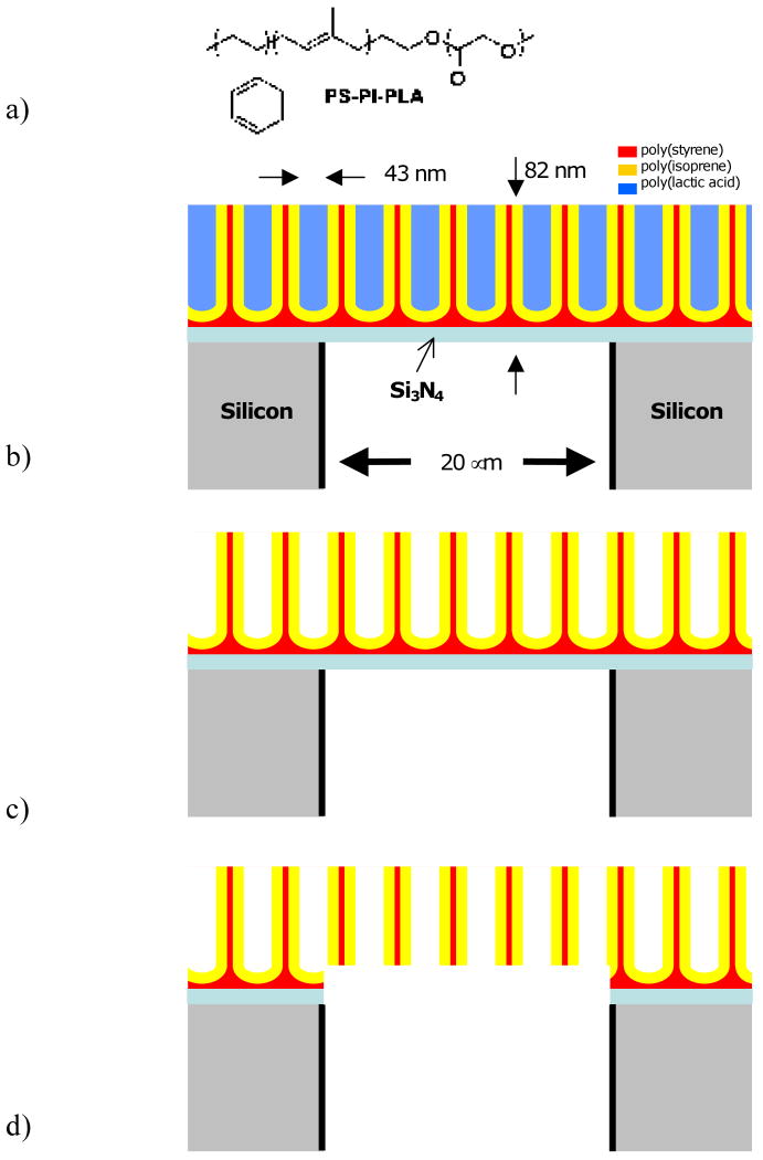
The strategy is to overlay a thin nanoporous membrane on a rigid, microporous silicon substrate, yielding an asymmetric membrane structure. In short, the microporous structure is formed by directional reactive ion etching (Bosch process) of a 100 μm thick Si wafer coated on both sides with Si3Ni4 and patterned on one side using a photomask into a square array of square (20 μm)2 pores with 20 μm separation. The etch is stopped at the downside Si3Ni4 layer. The wafer is then inverted. A block polymer solution [polystyrene-block-polyisoprene-block-polylactic acid, PS-PI-PLA (Fig. 9a), Mn=69,500, PDI=1.14, 56% PS, 10% PI, 34% PI wt%, in chlorobenzene] is spin coated onto the Si3Ni4 surface, followed by solvent evaporation. Due to the sizes and incompatibilities of the blocks, the polymers self assemble into a hexagonal array of cylindrical PLA “dots” that are lined by PI, all in a PS continuous phase (Fig. 9b). The PLA dots are removed upon exposure to aqueous NaOH, leaving behind an array of “test tube” structures, whose rounded bottoms are due to wetting of the Si3Ni4 substrate by PS (Fig 9c). Controlled chemical (HF) and plasma (oxygen) etch steps remove the bottom PS and underlying Si3Ni4, resulting in a nanoporous membrane carpeting the microporous silicon array. The nanopores are lined with PI, which can be used for later functionalization (Fig. 9d).
Figure 9.
a) Chemical structure of PS-PI-PLA block polymer.
b) Self-assembly of PS-PI-PLA on Si3N4, which in turn is on top of a microporous silicon support membrane. “Test tube structures” of PLA cylindrical dots form a hexagonal array. Here only a cross-sectional slice of the array is shown. Layers are not drawn to scale since micro- and nanofeatures are of vastly different size.
c) Same as b but with PLA removed.
d) Removal of Si3N3 and wetting PS layer yields continuous nano-microporous membrane. Apparently “floating” nanostructures form a tubular hexagonal lattice in 3D.
Figure 10 displays the asymmetric membrane, at two scales. The coarser scale is an electron micrograph visualizing the micropore array, and the inset is a tapping AFM image of the nanoporous block polymer carpet, revealing an average pore size 43 nm with 11% RSD. The thickness of the nanoporous membrane is 82 nm. Various mechanical challenges have attested to the ruggedness of this asymmetric membrane construct.
Figure 10.
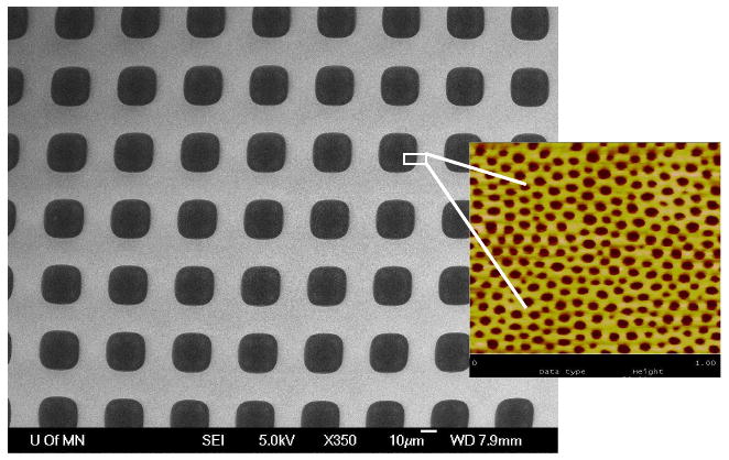
Electron micrograph of microporous Si array carpeted with nanoporous block polymer membrane. Inset: tapping AFM of nanoporous membrane. Blowup is not literal, as two images were taken separately.
Transport experiments with a small molecule (methyl orange, MO, MW=327g/mol) and a large molecule (dextran blue, DEX, MW=2×10⁶), summarized in Fig. 11ab, demonstrate that the asymmetric membrane is capable of size-selection, and therefore may be useful in protecting the hydrogel from very large macromolecules. Figure 11c demonstrates that removal of PLA is crucial in establishing membrane permeability to water-soluble solutes and that the PLA domains may completely span the polymer film.
Figure 11.

a) Transport of a small molecule (methyl orange, MO, 327 g/mol) and a large macromolecule, dextran blue, DEX, 2×10⁶ g/mol) through micro-nanoporous hybrid membrane.
b) Similar comparison of transport of MO and DEX through a control microporous membrane. Differences is slopes here are due to size-dependent (Stokes-Einstein) diffusion coefficients of MO and DEX. Comparing a and b results, it is seen that hybrid provides greater size selectivity.
c) Transport of MO across the hybrid membrane before and after removal of PLA block by spiking NaOH into receiver solution.
Reproduced from Ref. 53 with permission.
To further reduce the size of molecules that can enter a device, one may wish to utilize the vinyl constituents of the PI coating as grafting sites for polymer brushes or crosslinked nanogels that would fill the nanopores with a size selective mesh. The polystyrene surface may also be functionalized with other polymers that improve biocompatibility.
Concluding Remarks
This paper contains a combination of old and new material. We reviewed previously published work on a glucose-sensitive microsensor and microvalve, both of which depend on the swelling and shrinking of hydrogels based on p(MPBA-co-AAm). The analysis of sensor response which suggests that air compression contributes significantly to diaphragm reactance is new, as is the discussion of how polarity of response in both devices might be changed. The discussion of the nano/microporous membrane primarily recapitulates previously published work, although the suggestions for future modifications are new.
Most of the data and discussion regarding free swelling response of p(MPBA-co-AAm) hydrogels are new. While a model was presented for analyzing the results was presented, no fits were provided, primarily because the theory, which does not yet provide for glucose-mediate crosslinking and the observed increase in short term shear modulus accompanying shrinking, is incomplete. While this phenomenon is most striking at pH 10, the incongruence of swelling curves in response to glucose and fructose at pH 7.4 suggests that the glucose mediated crosslinking mechanism is also active at physiological pH. It is possible, using Eqs. (1)-(6), to fit the pH data of Fig. 3a and the fructose data of Fig. 3c, but the glucose data cannot be fitted. Alexeev et al. [27] suggested a way to include glucose-mediated crosslinking into a similar model. More comprehensive data and model evaluation will be needed to complete this aspect.
The analysis of relative swelling sensitivity to pH and glucose concentration for hydrogels that rely on OH- binding is important, since it suggests that devices that work by this mechanism may be not be sufficiently specific in their response to glucose, unless a purely pH-dependent compensating mechanism is provided. We suggest that replacing OH- with a copolymerized amine serving as a “constitutive” Lewis base, and relying on glucose-mediated crosslinking and shrinking, may improve selectivity to glucose.
As already mentioned, sensor and valve component sizes must be reduced to improve response time. It will be also be important to develop methods to introduce hydrogels into the devices that do not provide large resting pressures, which may reduce device reliability. Further work on microfabricated glucose sensors and closed-loop insulin delivery systems will require a close interplay between polymer chemistry, an understanding of the physical chemistry of hydrogel swelling as a function of glucose concentration and pH, and improved micro- and nanofabrication techniques.
Acknowledgments
This work was supported by NIH Grants EB003125, DK075739, HD040366, and HD051366, NSF Grant DMR-0605880, US Army Grant DA/DAMD17-02-1-0722, and a grant from the Spanish Ministry of Education, Culture, and Sports. We thank Prof. Marc A. Hillmyer and Drs. Anish Dhanarajan, Siddharthya Mujumdar, and Terry Davis for helpful discussions. Part of this work was carried out in the Institute of Technology Characterization Facility, University of Minnesota, which has received capital equipment funding from the NSF through the MRSEC, ERC and MRI programs. Other work was carried out in the Institute of Technology Nanofabrication Center, University of Minnesota, which receives partial support from NSF through the NNIN program.
Appendix I. Experiments with p(MPBA-co-AAm) Hydrogels
Preparation
Pregel solutions were loaded into glass capillaries (I.D. = 800 μm) and polymerized at room temperature for 12 hours. Typically, 200 mg of MPBA (with equimolar NaOH), AAm, and Bis were mixed with 5 μl TEMED, 0.5 mg APS, and distilled water to form a 1 ml pregel solution. The MPBA-co-AAm hydrogels were removed from the capillaries and equilibrated consecutively in distilled water and pH 7.4 PBS for 2 days at room temperature prior to the swelling experiments.
The same procedure was used to prepare slab hydrogel samples, except the pregel solution was polymerized between two glass plates separated by a 1 mm thick spacer. Water-equilibrated slab hydrogels were cut into 5 mm diameter discs for compression modulus measurements.
Swelling Experiments
Cylindrical hydrogels were cut into 2 mm-long segments and placed in vials containing 3 ml degassed 0.015 M PBS solutions with different pH values and glucose or fructose concentrations. Vials were tightly capped and placed in vacuum desiccators. Solutions were changed every 6 hours to avoid pH shift. Hydrogel diameters were measured under an optical microscope after 12 hours. Hydrogel swelling was found to be isotropic, so diameter measurements were readily converted to volumes.
Compression Modulus Measurements
Hydrogel disks were equilibrated in appropriate solutions and then loaded between two parallel plates of a Rheometer (Rheometric Scientific Inc., ARES), and uniaxial compression with a compression velocity of 25 μm/second was performed. The gap between the plates and the force applied were recorded. Shear modulus G was determined according to
where F is the normal force, A0 is the cross sectional area of the hydrogel disk before compression, and α is the compression ratio. Compression measurements were of short duration (<5 sec), so that no water was exuded from the hydrogels and the constant volume assumption was valid.
Appendix II. Derivation of Eq. (10)
Eq. (10) is derived by a first order perturbation analysis of diaphragm deflection around its unloaded state, where the hydrogel's swelling pressure, Δpsw is zero and the pressure in the gap is equal to atmospheric pressure, P0. Denoting the change in gap pressure due to deflection by Δpgap, we may write, in the linear regime [see Eq. (7)]
| (A1) |
Now the capacitor is bounded on top by the diaphragm and on the bottom by a rigid plate, and the two plates are assumed to be parallel in the unloaded state. We denote the areas of the diaphragm, the capacitor and the hermetically sealed cavity by AD, AC and AH, respectively. Let (x,y) denote coordinates of points along the two diaphragm, and g(x,y) be the distance between the two plates at that coordinate. In the unloaded state, g(x,y)=g0, constant, and the volume between the plates is V0=Ag0. In response to swelling pressure, the change in volume is
| (A2) |
where Δg(x,y) is the local deflection. Hence
| (A3) |
But according to the ideal gas law at constant temperature, (p0 + Δpgap)(V0 + Δpgap) = p0V0, hence
| (A4) |
On the other hand, the relative change in capacitance is given, in the linear regime, by
| (A5) |
Equation (10) results from combining Eqs. (A1), (A3), (A4), and (A5). Note that the approximations involved in this derivation may be unreliable at high swelling pressures, and that the linear approximations for gap pressure and capacitance may break down at different points. In particular, Eq. (A5) tacitly assumes parallel lines of electrical flux in a deflected capacitor, which will cease to be correct at high deflections.
Footnotes
Publisher's Disclaimer: This is a PDF file of an unedited manuscript that has been accepted for publication. As a service to our customers we are providing this early version of the manuscript. The manuscript will undergo copyediting, typesetting, and review of the resulting proof before it is published in its final citable form. Please note that during the production process errors may be discovered which could affect the content, and all legal disclaimers that apply to the journal pertain.
References
- 1.Flory PJ. Principles of Polymer Chemistry. Cornell University Press; 1953. [Google Scholar]
- 2.Katchalsky A. Polyelectrolyte gels. Prog Biophys Chem. 1954;4:1–59. [Google Scholar]
- 3.English A, Tanaka T, Edelman ER. Equilibrium and non-equilibrium phase transitions in copolymer polyelectrolyte hydrogels. J Chem Phys. 1997;107(5):1645–1654. [Google Scholar]
- 3.Ricka J, Tanaka T. Swelling of ionic gels: Quantitative performance of the Donnan theory. Macromolecules. 1984;17:2916–2921. [Google Scholar]
- 4.Firestone BA, Siegel RA. pH, salt, and buffer dependent swelling in ionizable copolymer gels: Tests of the ideal Donnan equilibrium theory. J Biomat Sci Polym Ed. 1994;5:433–450. doi: 10.1163/156856294x00130. [DOI] [PubMed] [Google Scholar]
- 5.Horkay F, Tasaki I, Basser PJ. Effect of monovalent-divalent cation exchange on the swelling of polyacrylate hydrogels in physiological salt solutions. Biomacromolecules. 2001;2:195–199. doi: 10.1021/bm0056153. [DOI] [PubMed] [Google Scholar]
- 6.English A, Mafe S, Mazanares JA, Yu X, Grosberg AY, Tanaka T. Equilibrium swelling properties of polyampholytic hydrogels. J Chem Phys. 1996;104(21):8713–8720. [Google Scholar]
- 7.Peppas N, Leobandung W. Stimuli-sensitive hydrogels: ideal carriers for chronobiology and chronotherapy. J Biomater Sci Polym Ed. 2004;15:124–144. doi: 10.1163/156856204322793539. [DOI] [PubMed] [Google Scholar]
- 8.Gil ES, Hudson SM. Stimuli-responsive polymers and their bioconjugates. Prog Polym Sci. 2004;29:1173–1222. [Google Scholar]
- 9.Kopecek J. Smart and genetically engineered biomaterials and drug delivery systems. Eur J Pharmaceut. 2003;20:1–16. doi: 10.1016/s0928-0987(03)00164-7. [DOI] [PubMed] [Google Scholar]
- 10.Kumar A, Srivastava A, Galaev IY, Matiasson B. Smart polymers: Physical forms and bioengineering applications. Prog Polym Sci. 2007;32:1205–1237. [Google Scholar]
- 11.Miyata T, Asami N, Uragami T. A reversibly antigen-responsive hydrogel. Nature. 1999;399:766–769. doi: 10.1038/21619. [DOI] [PubMed] [Google Scholar]
- 12.Gong JP, Katsuyama Y, Kurokawa T, Osada Y. Double-network hydrogels with extremely high mechanical strength. Adv Mater. 2003;15:1155–1158. [Google Scholar]
- 13.Haraguchi K, Takehisa T. Nanocomposite hydrogels: A unique organic-inorganic network structure with extraordinary mechanical, optical, and swelling/deswelling properties. Adv Mater. 2002;14:1120–1124. [Google Scholar]
- 14.Mujumdar SK, Siegel RA. Introduction of pH-sensitivity into mechanically strong nanoclay composite hydrogels based on n-isopropylacrylamide. J Polym Sci A: Polym Chem. 2008;46:6630–6640. doi: 10.1002/pola.22973. [DOI] [PMC free article] [PubMed] [Google Scholar]
- 15.Okumura Y, Ito K. The polyrotaxane gels: A topological gel by figure-of-eight crosslinks. Adv Mater. 2001;13:485–487. [Google Scholar]
- 16.Sakai T, Matsunaga T, Yamamoto Y, Ito C, Yoshida M, Suzuki S, Sasaki N, Shibayama M, Chung UI. Design and fabrication of a high-strength hydrogels with ideally homogeneous network structure from tetrahedron-like macromonomers. Macromolecules. 2008;41:5379–5384. [Google Scholar]
- 17.Kost J, Horbett TA, Ratner BD, Singh M. Glucose-sensitive membranes containing glucose oxidase: Swelling, activity, and permeability studies. J Biomed Mater Res. 1985;19:1117–1122. doi: 10.1002/jbm.820190920. [DOI] [PubMed] [Google Scholar]
- 18.Ishihara K, Kobayashi M, Ishimaru N, Shinohara I. Glucose induced permeation control of insulin through a complex membrane consisting of immobilized glucose oxidase and a polyamine. Polym J. 1984;16:625–631. [Google Scholar]
- 19.Podual K, Doyle FJI, Peppas NA. Preparation and dynamic response of cationic copolymer hydorgels containing glucose oxidase. Polymer. 2000;41:3975–3983. [Google Scholar]
- 20.Kang SI, Bae YH. A sulfonamide based glucose-responsive hydrogel with covalently immobilized glucose oxidase and catalase. J Controlled Release. 2003;86:115–122. doi: 10.1016/s0168-3659(02)00409-1. [DOI] [PubMed] [Google Scholar]
- 21.Albin G, Horbett TA, Miller SR, Ricker NL. Theoretical and experimental studies of glucose sensitive membranes. J Controlled Release. 1987;7:267–291. [Google Scholar]
- 22.Klumb LA, Horbett TA. Design of insulin delivery devices based on glucose sensitive membranes. J Controlled Release. 1992;18:59–80. [Google Scholar]
- 23.Li H, Luo R, Birgersson E, Lam KY. A chemo-electro-mechanical model for simulation of responsive deformation of glucose-sensitive hydrogels with the effect of enzyme catalysis. J Mech Phys Sol. 2009:369–382. [Google Scholar]
- 24.Shiino D, Murata Y, Kataoka K, Koyama Y, Yokoyama M, Okano T, Sakurai Y. Preparation and characterization of a glucose-responsive insulin-releasing polymer device. Biomaterials. 1994;15(2):121–128. doi: 10.1016/0142-9612(94)90261-5. [DOI] [PubMed] [Google Scholar]
- 25.Kataoka K, Miyazaki H, Bunya M, Okano T, Sakurai Y. Totally synthetic polymer gels responding to external glucose concentration: Their preparation and application to on-off regulation of insulin release. J Am Chem Soc. 1998;120:12694–12695. [Google Scholar]
- 26.Asher SA, Alexeev VL, Goponenko AV, Sharma AC, Lednev IK, Wilcox CS, Finegold DN. Photonic crystal carbohydrate sensors: Low ionic strength sugar sensing. J Am Chem Soc. 2003;125:3322–3329. doi: 10.1021/ja021037h. [DOI] [PubMed] [Google Scholar]
- 27.Alexeev VL, Sharma AC, Goponenko AV, Das S, Lebedev IK, Wilcox CS, Finegold DN, Asher SA. High ionic strength glucose-sensing photonic crystal. Anal Chem. 2003;75:2316–2323. doi: 10.1021/ac030021m. [DOI] [PubMed] [Google Scholar]
- 28.Alexeev V, Das S, Finegold D, Asher S. Photonic crystal glucose-sensing material for noninvasive monitoring of glucose in tear fluid. Clin Chem. 2004;50:2353–2360. doi: 10.1373/clinchem.2004.039701. [DOI] [PubMed] [Google Scholar]
- 29.Siegel RA, Gu Y, Baldi A, Ziaie B. Novel swelling/shrinking behaviors of glucose-binding hydrogels and their potential use in a microfluidic delivery system. Macromol Symp. 2004;208:249–256. [Google Scholar]
- 30.Baldi A, Gu Y, Loftness P, Siegel RA, Ziaie B. A hydrogel-actuated environmentally-sensitive microvalve for active flow control. IEEE J Microelectromech Sys. 2003;12:613–621. [Google Scholar]
- 31.Horgan AM, Marshall AJ, Kew SJ, Dean KES, Creasey CD, Kabilan S. Crosslinking of phenylboronic acid receptors as a means of glucose selective holographic detection. Biosens Bioelectron. 2006;21:1838–1845. doi: 10.1016/j.bios.2005.11.028. [DOI] [PubMed] [Google Scholar]
- 32.Kabilan S, Marshall AJ, Sartain FK, Lee MC, A H, Yang X, Blyth J, Karangu N, James K, Zeng J, Smith D, Domschke A, Lowe CR. Holographic glucose sensors. Biosens Bioelectron. 2005;20:1602. doi: 10.1016/j.bios.2004.07.005. [DOI] [PubMed] [Google Scholar]
- 33.Yang X, Lee MC, Sartain F, Pan X, Lowe CR. Designed boronate ligands for glucose-selective holographic sensors. Chem Eur J. 2006;12:8491–8497. doi: 10.1002/chem.200600442. [DOI] [PubMed] [Google Scholar]
- 34.Samoie GK, Wang W, Escobedo JO, Xu X, Schneider HJ, Cook RL, Strongin RM. A chemomechanical polymer that functions in blood plasma with high glucose sensitivity. Angew Chem Int Ed. 2006;45:5319–5233. doi: 10.1002/anie.200601398. [DOI] [PMC free article] [PubMed] [Google Scholar]
- 35.Springsteen G, Wang B. A detailed examination of boronic acid-diol complexation. Tetrahedron. 2002;58:5291–5300. [Google Scholar]
- 36.Yan J, Springsteen G, Deeter S, Wang B. The relationship among pKa, pH, and binding constants in the interactions between boronic acids and diols--it is not as simple as it appears. Tetrahedron. 2004;60:11205–11209. [Google Scholar]
- 37.Lorand JP, Edwards JO. Polyol complexes and structure of benzeneboronate ion. J Org Chem. 1959;24:709–774. [Google Scholar]
- 38.Overbeek JTG. The Donnan equilibrium. Prog Biophys Chem. 1956;6:57–84. [PubMed] [Google Scholar]
- 39.Lei M, Baldi A, Nuxoll EE, Siegel RA, Ziaie B. Hydrogel-based microsensors for wireless pH monitoring. Biomed Microdev. 2009;11:529–538. doi: 10.1007/s10544-008-9168-5. [DOI] [PubMed] [Google Scholar]
- 40.Candau S, Bastide J, Delsanti M. Structural, elastic, and dynamic properties of swollen polymer networks. Adv Polym Sci. 1982;44:27–71. [Google Scholar]
- 41.Mujumdar SK. PhD Thesis. University of Minnesota; Minneapolis, MN: 2007. [Google Scholar]
- 42.Matsumoto A, Yoshida R, Kataoka K. Glucose-responsive polymer gel bearing phenylborate derivative as a glucose-sensing moiety operating at physiological pH. Biomacromolecules. 2004;5:1038–1045. doi: 10.1021/bm0345413. [DOI] [PubMed] [Google Scholar]
- 43.Shiino D, Kubo A, Murata Y, Koyama Y, Kataoka K, Kikuchi A, Sakurai Y, Okano T. Amine effect on phenylboronic acid complex with glucose under physiological pH in aqueous solution. J Biomat Sci, Poly Ed. 1996;7:697–705. doi: 10.1163/156856296x00462. [DOI] [PubMed] [Google Scholar]
- 44.Kawasaki T, Ahanuma H, Yamanouchi T. Increased fructose concentrations in blood and urine in patients with diabetes. Diabetes Care. 2002;25:353–357. doi: 10.2337/diacare.25.2.353. [DOI] [PubMed] [Google Scholar]
- 45.Han IS, Han MH, Kim J, Lew S, Lee YJ, Horkay F, Magda J. Constant-volume hydrogel osmometer: A new device concept for miniature biosensors. Biomacromolecules. 2002;3(12711275) doi: 10.1021/bm0255894. [DOI] [PubMed] [Google Scholar]
- 46.Lin G, Chang SF, Kuo CH, Magda JJ, Solzbacher F. Free swelling and confined smart hydrogels for applications in chemomechanical sensors for physiological monitoring. Sens Act B. 2009;136:186–195. doi: 10.1016/j.snb.2008.11.001. [DOI] [PMC free article] [PubMed] [Google Scholar]
- 47.Lei M, Baldi A, Nuxoll E, Siegel RA, Ziaie B. A hydrogel based implantable micromachined transponder for wireless glucose measurement. Diabet Technol Therap. 2006;8:112–122. doi: 10.1089/dia.2006.8.112. [DOI] [PubMed] [Google Scholar]
- 48.Chau HL, Wise KD. Scaling limits in batch-fabricated pressure sensors. IEEE Trans Electron Dev. 1987;34:850–858. [Google Scholar]
- 49.Lei M, Ziaie B, Nuxoll E, Ivan K, Noszticzius Z, Siegel RA. Integration of hydrogels with hard and soft nanostructures. J Nanosci Nanotechnol. 2007;7:780–789. doi: 10.1166/jnn.2007.513. [DOI] [PubMed] [Google Scholar]
- 50.Farmer TGJ, Edgar TF, Peppas NA. The future of open- and closed-loop insulin delivery systems. J Pharm Pharmacol. 2008;60:1–13. doi: 10.1211/jpp.60.1.0001. [DOI] [PMC free article] [PubMed] [Google Scholar]
- 51.Huang CJ, Chen YH, Wang CH, Chou TC, Lee GB. Integrated microfluidic systems for automatic glucose sensing and insulin injection. Sens Act B. 2007;122:461–468. [Google Scholar]
- 52.Tsai HKA, Moschou EA, Daunert S, Madou M, Kulinsky L. Integratable biosensors and drug delivery: A step closer to scalable responsive drug-delivery systems. Adv Mater. 2009;21:656–660. [Google Scholar]
- 53.Nuxoll EE, Hillmyer MA, Wang R, Leighton C, Siegel RA. Composite block polymer-microfabricated silicon nanoporous membrane. ACS Appl Mater Interf. 2009;1:888–893. doi: 10.1021/am900013v. [DOI] [PMC free article] [PubMed] [Google Scholar]
- 54.Anderson JM. Biological responses to materials. Annu Rev Mater Res. 2001;31:81–110. [Google Scholar]
- 55.Ratner BD, Bryant SJ. Biomaterials: Where we have been and where we are going. Ann Rev Biomed Eng. 2004;6:41–75. doi: 10.1146/annurev.bioeng.6.040803.140027. [DOI] [PubMed] [Google Scholar]
- 56.Koschwanez HE, Reichert WM. In vitro, in vivo and post explantation testing of glucose-detecting biosensors: Current methods and recommendations. Biomaterials. 2007;28:3687–3703. doi: 10.1016/j.biomaterials.2007.03.034. [DOI] [PMC free article] [PubMed] [Google Scholar]
- 57.Ainslie K, Desai TA. Microfabricated implants for applications in therapeutic delivery, tissue engineering, and biosensing. Lab Chip. 2008;8:1864–1878. doi: 10.1039/b806446f. [DOI] [PMC free article] [PubMed] [Google Scholar]


