

Abstract
We describe a prototype system built to allow open-access very-low-field MRI of human lungs using laser-polarized 3He gas. The system employs an open four-coil electromagnet with an operational B0 field of 4 mT, and planar gradient coils that generate gradient fields up to 0.18 G/cm in the x and y direction and 0.41 G/cm in the z direction. This system was used to obtain 1H and 3He phantom images and supine and upright 3He images of human lungs. We include discussion on challenges unique to imaging at 50 –200 kHz, including noise filtering and compensation for narrow-bandwidth coils.
Keywords: laser-polarized noble gas, low magnetic field, magnetic resonance imaging, lung imaging, open access
INTRODUCTION
Recent advances in optical pumping (1, 2) have made laser-polarized 3He MRI a powerful method of exploring pulmonary structure and function (3, 4). 3He imaging of human lungs is now performed commonly in clinical MRI scanners to explore a variety of lung disorders (5) using techniques such as spin-density imaging (6), flow mapping (7, 8), and diffusion imaging (9, 10). Additional notable achievements include monitoring of 3He relaxation as an indicator of the local alveolar O2 concentration (11), which has recently been directly linked to the physiologically relevant ventilation/perfusion ratio (V/Q) (12).
These advances are enabled by the high nuclear spin polarization obtainable from optical pumping methods, typically greater than 10% (1, 2). Such hyperpolarization, which for 3He can be 10,000 times greater than the polarization obtained by thermal equilibrium at 1 T, yields a magnetization that is similar to those found in water and other liquids when placed in such large external magnetic fields. Additionally, because the 3He spins are polarized prior to the imaging procedure, a large applied magnetic field B0 is not required for high-resolution MRI (13). Therefore, laser-polarized 3He MRI can be performed at applied magnetic fields substantially lower than in clinical scanners, potentially <10 mT (100 G), with obtainable SNR and resolution for lung imaging approaching that obtained using clinical scanners.
Such a result is true, even though the NMR signal induced by a sample scales directly with Larmor frequency and is thus reduced by using a smaller B0 and correspondingly lower RF frequency. For prepolarized samples, the ideal B0 value is that where sample noise has not yet begun to dominate, while NMR signal has been maximized with respect to coil (or Johnson) noise. For laser-polarized 3He in samples the size of human lungs, this value has recently been determined to be ~0.1– 0.2 T (14). At B0 above this value, signal is lost due susceptibility-induced background gradients, which result in significantly reduced , line broadening and inherent loss of resolution at B0 as high as that commonly encountered in clinical MR scanners. In contrast, susceptibility-induced gradients are negligible for B0 ~10 mT; as a result, T2 and may be over an order of magnitude larger at very low fields, helping to offset the reduction in NMR signal obtained from operating at lower RF frequency. Laser-polarized 3He lung imaging at B0 ~5–10 mT can thus yield MRI images with resolution and SNR only about three times lower than values obtained at 1.5 T (14), assuming a similar 3He polarization level and absolute B0 homogeneity.
We have exploited the ability to perform laser-polarized 3He MRI at significantly lower applied fields than in traditional clinical scanners and built a novel, open-access MRI magnet in which subjects can change their orientation and be imaged in any posture between horizontal and vertical. Such a system would permit orientationally dependent studies that are impossible by clinical MRI scanners, where subjects can only be imaged in the supine position. This research is driven by current interest in the pulmonary physiology community, where the effect of gravity, posture, and body orientation on pulmonary ventilation and perfusion is a subject under much debate (15, 16, 17). A major limitation in this area is the lack of a method to obtain quantitative, high-resolution maps of lung ventilation and perfusion with the subject in different orientations. Despite minimal orientation possible within the confines of a traditional human MRI scanner, some initial studies have shown that posture changes from supine (face up) to prone (face down) and to decubitus (sideways) affect the lung physiology in a way that can be clearly probed by 3He MRI (18). Very-low-field 3He MRI incorporating novel, open-access magnet designs can provide this area of pulmonary physiology with a powerful tool for studying orientational and posture-related effects.
We initially demonstrated the feasibility of low-field 3He MRI using a solenoid magnet operating at approximately 2 mT (20 G) (13, 19) and obtained 3He images of sealed glass cells (13) and excised rat lungs (19). This system achieved image resolution comparable to that obtained with clinical scanners, although with much smaller samples, while the reduction of susceptibility-induced gradients was seen in both the cells and rat lungs. We measured a 3He of >100 ms at 2 mT in excised rat lungs, as opposed to ~5 ms at 1.5 T (19). More recently, several groups have performed in vivo human lung 3He MRI at fields of 0.15 T (20), 0.1 T (21), 15 mT (22), and 3 mT (23, 24) using clinical scanners with resistive (21, 23), permanent (20), or ramped-down superconducting (22) magnets. One study has been performed with a subject standing in a resistive magnet system operating at 3 mT (24).
We have now used a prototype, open-access MRI system operating at 4 mT to perform, for the first time, in vivo human lung 3He MRI with a subject in both supine and vertical positions (25). In this article, we describe in detail this prototype MRI system. This first-generation system was assembled from existing components in a physics laboratory, augmented by simple, low-cost elements such as in-house-built planar gradients and surplus commercial equipment. As such, the prototype scanner was not an optimized system, and the resulting human lung images were not expected to match those of a clinical scanner. Rather, this demonstration system was intended to illustrate the possibilities of open-access, orientationally dependent human lung imaging using polarized noble gases, while informing a careful design process for future optimized systems. Below, we describe the operating details and specifications for the prototype imager and report results of 3He and 1H diagnostics during development. In addition, we discuss some of the unique challenges associated with human MRI at very low fields, outline solutions implemented at the time, and discuss the possibility for improvements in a second-generation imager.
EXPERIMENTAL DESIGN AND IMPLEMENTATION
A simplified schematic diagram of the very-low-field, open-access human MRI system is shown in Fig. 1. In the following sections we discuss the design and specification of each component of the apparatus.
Figure 1.

Simplified schematic diagram of the very-low-field, open-access, human MRI system. The major components include a commercial MRI research console (left), additional electronics components added or modified for RF and gradient pulse generation and B0 control (center), and the B0, field gradients and B1 coils, located inside an RF-shielding Faraday cage (right).
Open-Access Electromagnet
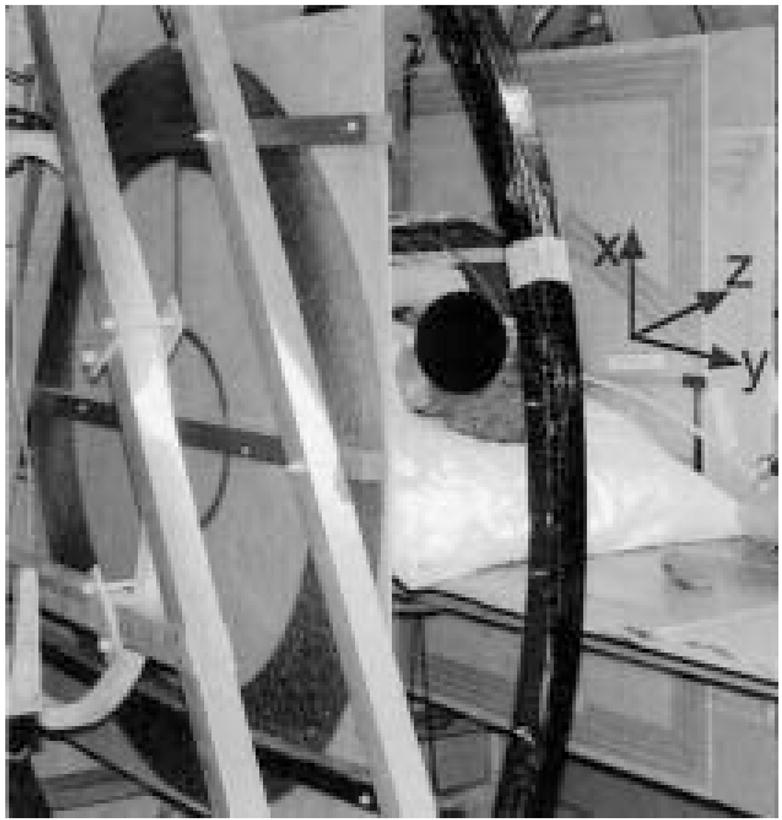
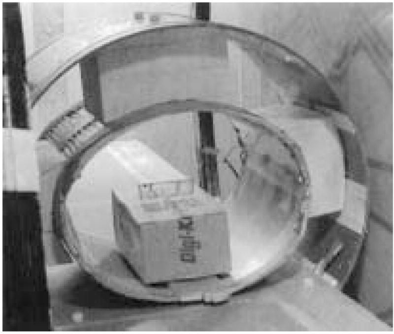
The B0 field was produced by two pairs of resistive coils. The larger pair consisted of 2-m diameter coils, each with 120 turns of copper wire (DC resistance = 0.91Ω), and with the planes of the coils separated by 73.6 cm. The second pair— used for field correction and homogeneity optimization— consisted of two 86-cm diameter coils, each with 100 turns of copper wire (DC resistance = 0.11 Ω), and with planar separation of 120 cm. Both pairs were vertically mounted on large triangular aluminum brackets, and their coil positions and relative currents were optimized for field uniformity within a 30-cm-diameter spherical region. Field calculations were made by applying the Biot-Savart equation to small segments of the coils. The assembly was positioned inside a large steel RF-shielded Faraday cage (8 ft. wide × 12 ft. long × 8 ft. high) with the coil axis across the width of the Faraday cage. In Fig. 2, two photographs show the four coils with dimensions and axes indicated.
Figure 2.

Photographs of the very-low-field open-access human MRI magnet system showing the placement of the B0 coils: a) Large B0 coils, labeled “1,” with diameter D = 2 m, separation ΔH = 0.74 m. Lab frame coordinates are included in this photograph. b) Small coils, labeled “2,” with diameter d = 0.86 m, separation Δh = 1.2 m. Human subject is shown in the horizontal imaging position.
The two pairs of coils were powered by different current sources: the larger pair was driven by two Sorensen SRL 40 –50 power supplies connected in series, and the smaller pair was supplied by a Hewlett-Packard 6012A. Laboratory electronics and other noise sources within the relevant range of NMR observational frequencies (50 –200 kHz) required careful filtering of all power lines leading to the imager. The DC current feeds to the coils were filtered to prevent transmission of broadband Kilohertz frequency noise, using large capacitors connected in parallel at the output of the power supplies and LC filters mounted on the feed-through panel of the Faraday cage. The B0 field generated at the central imaging volume by this configuration was 1.34 G/A for the large pair of coils and 0.68 G/A for the small pair. There was no active cooling method employed; the maximum resulting field was limited by the coils power supplies (7 mT), whereas the operating field was limited by the heat generated by the B0 coils inside the Faraday cage (4 mT). As a result of the warm-up time of the power supplies and the coils, it was necessary to wait up to 1 hour before a stable B0 coil temperature and current were achieved.
The optimum current ratio between the large and small coils was ~5 as predicted by initial calculations and confirmed by SNR measurements on water phantoms of various sizes and small 3He cells. Although the coils were bolted in place and their position was not adjustable, B0 shimming was still possible via added current offsets to the gradient coils through the gradient amplifiers. After optimization by coils currents adjustment, B0 was mapped by measuring the proton NMR frequency from a small water sample and receive coil that were moved around in the central horizontal plane on a 2.5-cm grid pattern inside the large transmit coil. A plot of the measured field uniformity in the horizontal yz plane of the system is shown in Fig. 3. The measured field uniformity differed from optimization calculations. The field was slightly greater on the negative z axis (see Fig. 2 for coordinate axes), due to the smaller diameter of the left large coil, and slightly greater along the negative y axis due to proximity of the Faraday cage steel wall.
Figure 3.
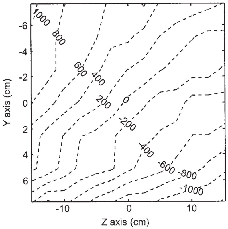
Measured B0 field deviation map (ppm). The plot was generated by moving a small water phantom along a 1 inch grid and recording the NMR frequency at each point.
Open-Access Gradient Coils
Planar gradient coils were built on 3-mm-thick G10 plastic sheets using three layers of 1.2-cm wide, 40-μm-thick copper tape as the conductive material. The coil design was created using a procedure in which the 3D magnetic field distribution was calculated from the sum of fields created by small elements of the gradient coils, and the coil pattern was varied iteratively to maximize gradient strength and optimize linearity across a 60-cm diameter central imaging volume. The x and y gradients were wound on a 90 × 120 cm sheet, had a 0.78 Ω DC-resistance for each pair, an inductance of 92.2 μH, and an output field of 1.37 × 10⁻³ G/cm/A. The z gradient pair had a spiral form wound on a 120 × 120 cm sheet, a measured 1.29 Ω DC-resistance, an inductance of 368.8 μH, and an output of 4.82 × 10⁻³ G/cm/A. Both gradient designs are shown in Fig. 4.
Figure 4.
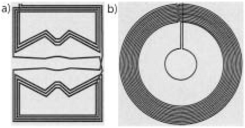
Winding patterns for planar gradient coils designed for the open-access human MRI system. a) x and y-axis planar gradient design, on a 90 × 120 cm plane; b) z-axis planar gradient design, on a 120 × 120 cm plane.
The gradient sheets were attached to the same aluminum brackets as the main B0 coils, leaving a gap of 71 cm for the placement of a subject table, B1 coils, and the imaging subject. Figure 5 shows the three planar gradients installed in the system. The gradients were powered using Techron 8606 amplifiers—the maximum currents supplied for our gradients were 130 A for the x and y and 86 A for the z gradient. This resulted in maximum gradient fields of 0.18, 0.18, and 0.41 G/cm for the x, y, and z gradients, respectively. The magnetic field gradients deviated from linearity by no more than 0.4% across the central imaging region, easily exceeding the requirements for the imaging resolutions shown and discussed in later sections. Because of the poor thermal conductivity of the gradient plastic sheets, heating of the copper tape limited the pulsed gradient repetition time to at least 100 ms in imaging sequences.
Figure 5.
The planar gradient sets mounted on the aluminum support frame of the open-access human MRI B0 coil system. The x and y gradients are placed just inside of the z gradients, relative to the subject (seen in supine position). As such the z-axis gradient is visible on the subject’s left, and the x-axis gradient is seen to his right.
Gradient line filtering was a special challenge given the proximity of the desired bandpass frequencies (1–2 kHz) and those to be filtered (50 –200 kHz). Each of the three gradient coil power lines were filtered with simple passive inductors built with ferrite toroid cores (Ferroxcube TX63/28/25). Both the output and sample common lines from each of the three Techron amplifiers were wound 20 times around these small toroids using a 10-gauge connection wire. These passive inductors blanked the gradient lines when the amplifier was not generating a pulse, effectively reducing their noise to quiescent levels. As these passive filters functioned effectively only when a gradient pulse was not applied and the ferrite core stayed unsaturated, the readout gradient required an additional filtering mechanism during the image acquisition. These filters consisted of two larger toroid ferrite cores (Ferroxcube T107/65/25), each double-wound in a transformer configuration (2 × 9 windings). One side of windings contained one wire of the readout gradient, while the second winding was connected directly to a Sorensen SRL 10–50 DC power supply that matched the readout gradient current during signal acquisition. This way, the ferrite became unsaturated while the gradient was on during the image acquisition, reducing the baseline noise level to within a factor of two of that obtained when the gradient amplifier was off. To permit this filtering method, the Techron amplifier assigned for the readout gradient was set to constant-voltage mode, mainly because the constant-current setting was unstable and noisy. Although this proved to be successful in reducing noise, the slew rate of the readout gradient amplifier was slower than the others because the attached z-gradient coil possessed a greater inductance than the others, causing the shapes of each pulse to be slightly distorted on rise and fall.
RF Coils and System Control
A commercial MRI research console from Surrey Medical Imaging Systems (SMIS) was used for RF and gradient pulse control and signal reception. The console did not have the hardware to produce the Kilohertz-range imaging frequencies required for the low B0 field strengths used, so we implemented a heterodyne mix-down stage for the transmit signal and a mix-up for the receive signal using a reference signal of 20 MHz from the PTS-160 synthesizer in the SMIS console, and ZAD-3 mixers (Mini-Circuits, Brooklyn, NY). Separate transmit and receive B1 coils were used, which allowed straightforward impedance matching of the RF amplifier to the transmit coil and the preamplifier to the receive coil.
The transmit B1 coil was built in a Helmholtz configuration with five windings on each side using 12-gauge copper wire on a 66-cm-diameter PVC pipe as a form. The RF transmit signal was fed into a two-stage amplifying system: a home-built amplifier allowing a gate conditioning for the output, followed by one of the five channels of a 5 × 165 W audio amplifier (Outlaw Audio, Durham, NH). A crossed-diode box after the amplifiers, along with noise blanking of the audio amplifier, provided noise isolation. Tuning of the transmit coil was achieved with high-voltage resonance capacitors that were connected in series with the coil to establish a low output impedance on the audio amplifier (~4 Ω). The quality factor Q of the transmit coil resonance was ~10. The inductance of the B1 transmit coil yielded a finite rise time from 10 to 150 μs, depending on the resonant frequency.
During system development, a variety of small, solenoidal RF coils, which could be easily tuned to 100 –200 kHz, were used as receive coils. The human receive coil was designed to fit a medium-sized human chest: the coil was wound in a cosine pattern with 4 × 80 turns on an ellipsoidal shape form 44 cm wide × 33 cm high × 38 cm long. The receive coil consists of a parallel resonant circuit with an output impedance of ~100 kΩ, which was well matched to a Stanford Research Systems SR560 preamplifier in line between the coil and the mix-up stage prior to digitization by the SMIS. The receive coil was tuned from 54 –200 kHz using “resonance boxes” with multiple capacitor configurations. The Q of this coil was ~80 –120, depending on the operating frequency. Such high Q values at frequencies ~100 kHz resulted in coil response bandwidths of ~1–2 kHz, significantly less than typical imaging spectral widths of 10 –20 kHz. As a result, all images acquired from this system required postprocessing to remove the convolved effect of the frequency response of the coil.
Inductively detected noise from living tissue is insignificant at low-RF frequencies. Thus the resonances of the B1 coils were not affected by the presence of a human imaging subject. However, significant problems (noise and distortion of resonances) were caused by coupling between the transmit and receive coils and between the receive coil and the gradient coils during switching. Noise was significantly reduced by carefully aligning the transmit and receive coils orthogonally to each other, blanking the preamplifier during RF transmissions and adding a 3– 4-ms dead time employed after the transmit pulse. In addition, precise positioning of the receive coil in the magnetic center of the gradients greatly reduced the unwanted receive signal during gradient switching. The human coils were bolted together to maintain orthogonality and were fixed to the subject imaging table, as shown in Fig. 6.
Figure 6.
Photograph of the transmit and receive coils for the open-access human MRI system. The large Helmholtz transmit coil was bolted onto the subject imaging table, and the receive coil was attached using foam spacers and plastic bolts.
The existence of several environmental noise signals within our operating frequencies necessitated the use of a steel Faraday cage that enclosed the electromagnet. This room was designed to attenuate RF interference in the range of 10 kHz to 10 MHz by up to 100 dB. A low-noise power transformer was used to deliver electrical power inside the room. A feed-through panel was made from thick aluminum, and all the electrical connections were fed through using multiple passive filtering elements. Lower noise attenuation was detected at different points of the cage, mostly in the corners and in some places where the steel panels where jointed together. Where necessary, copper tape with conductive adhesive was added for a better electrical connection between cage panels, reducing the environmental noise level.
Subject Orientation
The human subject was imaged in two positions: supine and sitting upright. For supine imaging, a wooden bed was constructed to fit within the imaging area for the subject to lie on top. The transmit coil was bolted to the bottom of the bed (see Fig. 6) and the subject lay within the receive coil (see Fig. 2b). To prevent deformation of the receive coil by the subject, a small weight-bearing bridge was placed just over the inside of the receive coil for the subject to lie upon.
For upright imaging, the wooden bed was replaced by a stool on which the subject sat. Horizontal plastic beams were mounted onto the aluminum frame to provide a secure mounting point for the transmit and receive coils. The subject was able to lean slightly against the receive coil for stability during the imaging session.
All human experiments were performed according to a protocol approved by the Institutional Review Board at the University of New Hampshire. The subject for lung imaging was a healthy 47-year-old male.
3He Polarization and Delivery
Highly polarized 3He was produced using the well-established method of spin-exchange of an optically pumped dense Rb vapor with 3He gas (1). For human imaging studies that require large volumes of laser-polarized 3He, a modular 3He polarization apparatus was built, complete with gas storage, transport, and delivery stages similar to those previously implemented for 129Xe imaging (26).
The glass optical pumping/spin-exchange cells on this polarizer were constructed from GE-180 aluminosilicate cylinders (~80 cm3 volume) and contained a few milligrams of Rb. Each cell was enclosed in a dedicated Pyrex outer jacket that served as an oven through which heated dry air was blown. The cell-oven combination was connected to the polarizer via a detachable glass valve connection, allowing its removal and placement in the MR imager so that diagnostic NMR could be performed directly on the cell without loss of 3He gas. The cell could then be reattached to the polarizer and repumped.
Typically, the cells were optically pumped at 195–210°C (~2-hour spin exchange time). For each experiment, the cell was filled with 5– 6 bar of 3He and 0.1 bar of N2. Two fiber-coupled LDAs (Coherent, Inc., Santa Clara, CA) each provided 30 W of continuous-wave laser light at 795 nm with a nominal 2-nm line width (FWHM). A pair of linear polarizing beam splitters and birefringent crystals converted this output into circularly polarized light in one orientation before reaching the cell. A simple 1-m-diameter Helmholtz pair of coils produced the magnetic field, typically ~10 G, for optical pumping.
3He polarization reached ~20 – 40% after spin-exchange optical pumping for ~4 – 8 hours. The cell was either removed from the polarizer for direct 3He NMR in situ, or the 3He was allowed to expand from the pumping cell into a previously evacuated glass and Teflon compressor for storage and subsequent delivery. Transfer of the gas to the compressor always occurred after the cell had cooled to room temperature so that all the Rb was condensed on the cell wall. As an extra safety precaution, 3He gas was passed through a plastic air filter en route to the compressor to condense any possible remaining gaseous Rb atoms. 3He was delivered from the compressor via narrow Teflon tubing that passed through a feed-through in the Faraday cage to the delivery manifold located adjacent to the human subject. The delivery manifold for human subjects consisted of a Tedlar bag, vacuum and inert gas ports, and a Teflon tube used for inhalation.
In addition to polarization of large volumes of 3He via the dedicated polarizer described, small spherical and cylindrical sealed glass cells containing 3He were polarized and used in diagnostics during development of the imager. The cells, ranging in volume from ~20 –100 cm3 and pressure from 3– 8 bar, were optically pumped in a small ceramic oven heated with hot air up to 170°C, and circularly polarized 795-nm laser light provided by a single 15-W LDA (Optopower, Tuscon, AZ) with a broad 2–3-nm FWHM line width. These cells were optically pumped for at least 4 hours.
MRI Techniques
The small solenoid test coils or the body coils were tuned to frequencies between 100 and 200 kHz, and 3He or 1H (water) signals were acquired. The corresponding B0 fields were between 2.2 and 6.2 mT. Often, the same coil was used to acquire 3He or 1H signals simply by varying B0 with the DC power supply controls. This B0 adjustment also made it easy to center the 3He or 1H signal on the receive coil resonance without requiring adjustment of the transmitter or receiver offset via the console software.
Initial diagnostics and SNR measurements were made using a standard single hard-pulse FID sequence. Generally, the pulse width was set to 100 –500 μs to allow the leading edge of the RF pulse to reach a consistent value and approximate a square shape. Spectral widths were set between 5 and 25 kHz, the number of data points ranged from 128 to 4,096, and low flip-angle excitations for 3He or 90° pulse excitations for water were achieved by adjustment of the coarse power modulation setting and the fine RF transmitter amplitude settings in the SMIS software. A dead time of 3– 4 ms was usually added before signal detection to allow for sufficient coil ring-down and to avoid acquiring any coupling response of the coils overlapped with spectral information.
Laser-polarized 3He T1 and flip-angle calibrations were measured using multiple repetitions of a single pulse-acquire sequence, with repetition times, TR, of seconds for flip-angle calibrations, and of minutes for 3He T1 measurements. Both flip angle or 3He T1 were determined using the method described in (19). All 3He imaging experiments were conducted with standard spin-warp gradient echo (FLASH) sequences based on code supplied with the SMIS instrument. Gradient calibration constants were set accurately in the SMIS software. The echo time, TE, was minimized by using wider spectral widths (10 –20 kHz) and smaller data sets (64 or 128 points); TR was limited by the heat dissipation of the gradient panels to 100 –500 ms. Generally, to optimize SNR, slice selection was not used. Usually only one signal averaging scan was acquired for each 3He image. Human 3He lung imaging was performed at 3.9 mT (39 G) with B1 set to 127 kHz. The Q of the human transmit and receive resonance circuits were 9.7 and 83.3, respectively, with a receive coil frequency response FWHM of 1.5 kHz. The gradient-echo imaging sequence employed nonsequential (centric) phase encoding, TE = 10 ms, TR = 100 ms, and a flip angle of 8°. The RF imaging pulses were typically five-lobe sinc shapes of 1 ms duration. The sinc-shaped pulse was chosen for an eventual slice-selection implementation and because it suffered less noticeable distortion than the square pulse in the low-Q transmit coil system. A field of view (FOV) of 50 cm and an imaging matrix of 128 × 64 were used. The raw data were zero-filled before fast Fourier transformation.
For human experiments, the subject took three or four deep breaths, each lasting 1–2 seconds, while polarized 3He gas was delivered to the Tedlar bag. After filling, the Tedlar bag was sealed off from the He polarizer. Once the subject completed the last deep breath and was at relaxed expiration, we opened the valve between the Tedlar bag and the mouthpiece and the subject was instructed to breathe in all the gas from the bag, ~500 cm3 of polarized 3He, via the tubing. This was followed by a small intake of room air to chase the 3He deeper into the lungs. MR imaging or spectroscopy sequences commenced immediately, and the subject maintained this breath hold for 20 –50 seconds. Once imaging was complete, the subject was asked to exhale and to follow with three or four deep breaths of room air.
RESULTS
Prior to implementation of the human B1 coils, the first 3He images with the very-low-field, open-access human MRI system were acquired using sealed cells, with B0 set to 4.1 mT and operating at a Larmor frequency of 132 kHz. Shown in Fig. 7(a) is an image of the phantoms that had been used previously in bench-top low-field MRI experiments (13). The images are undistorted, indicating true gradient linearity across this smaller FOV, as well as a SNR of ~30. The resolution is close to 1 mm2, with no slice selection.
Figure 7.

a) Images of 3He laser-polarization cells, obtained at 4.1 mT with the very-low-field, open-access, human MRI system, using a gradient echo sequence with the following parameters: 132 kHz, 50 cm acquired FOV, 128 × 128 pixels, TE = 10 ms, TR = 500 ms, and two averages. b) 1H image of a large tub containing water, obtained at 3.0 mT with the 3He very-low-field MRI system. A spherical plastic rod was placed across the bottom of the tub to provide image structure. A spin echo sequence was used with the following acquisition parameters: 127 kHz, 125 cm acquired FOV, 128 × 128 pixels, TE = 36 ms, TR = 2.4 s, and 48 averages.
Initial SNR and imaging tests with the human receive coil were performed using water in a large tub (14.5 cm height × 25 cm wide × 38 cm long), with B0 = 3.0 mT, giving a proton Larmor frequency of 127 kHz. Figure 7(b) shows a 2D water image obtained using a spin echo sequence with 48 signal averages. The image shows the effect of small B0 field instabilities for this long experiment (over 4 hours), but there is reasonable spatial resolution (~1 cm2) and SNR considering the low proton polarization at this field (103 times lower than for a 3 T imager).
Before human imaging began, a number of tests were performed to characterize the 3He polarizer. First the polarization cells were placed directly in the MRI system, and the 3He T1 was measured to be 6 –20 hours, depending on the cell used. The storage compressor was detached and placed in the imager, where the 3He T1 was ~20 minutes. Polarized 3He was also transferred into a Tedlar sample bag using the delivery manifold described earlier, and 3He T1 was measured to be ~20 minutes. Images of the polarization cell and filled Tedlar bags were commonly obtained. Although not applied to human imaging, slice selection was tested and calibrated using two polarized 3He cells simultaneously.
Figure 8 shows an example 3He lung image acquired with the subject lying supine on the nonconducting, nonmagnetic subject table. This image indicates clear definition of the lung lobes, with largely uniform 3He signal. The medial aspect of the left lung (shown on the right of the image) has a lower intensity consistent with the location of the heart. The B1 coils were also rotated for vertical-orientation lung imaging, as discussed elsewhere (25). The image has a maximum SNR ~10, and a resolution of 4 × 8 mm.
Figure 8.
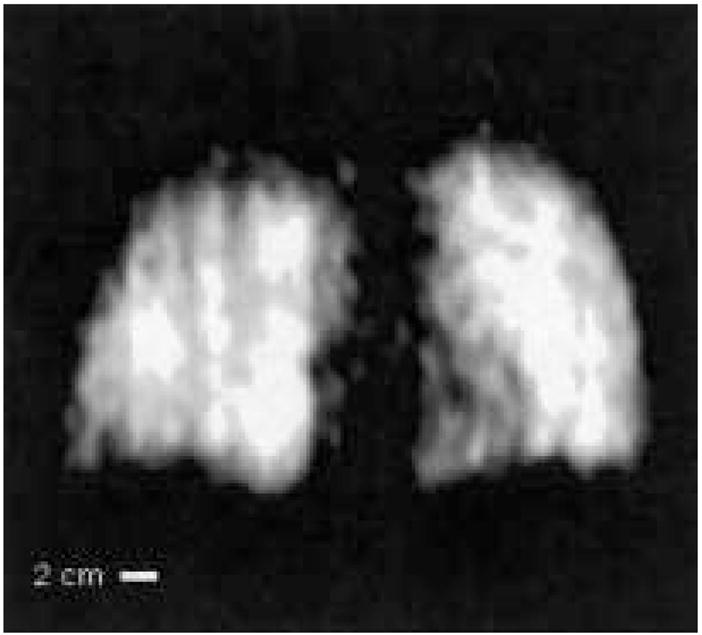
Example 3He human lung MR image obtained at B0 = 3.9 mT (127 kHz) in the very-low-field, open-access human MRI scanner. The subject was supine. Acquisition parameters included spectral width = 16.7 kHz, acquired FOV = 50 cm, 128 × 64 image zero-filled to 128 × 128, TE = 10 ms, TR = 100 ms, no signal averaging, with an acquisition time of seven seconds. Coil response correction was implemented in post-processing (see Discussion). From reference (25).
DISCUSSION
The initial human lung images obtained from this prototype very-low-field, open-access human-scale MRI system successfully demonstrated the ability for such an instrument to obtain pulmonary anatomical information as a function of subject orientation (25) and showed the potential for similar studies involving quantitative measurements of pulmonary function. The SNR for these first images was lower than theoretical predictions, which should have approached the imaging quality obtained in clinical MRI scanners (14). This prevented us from using a slice selection gradient to obtain finer details of lung structure and resulted in full-projection images with SNR ~10. However, this does not reflect an inability of very-low-field MRI to yield clinical-quality images of inhaled 3He in the human lung, but rather highlights the engineering challenges that remain in custom-designing very-low-field MRI scanners that operate well below the frequency range of traditional clinical MRI scanners (22, 23, 25).
As explained briefly in the introduction, 3He MRI is theoretically possible at applied fields lower than those in clinical scanners, potentially ~10 mT (100 G), with obtainable SNR and resolution for lung imaging approaching that obtained using clinical scanners. This is despite the fact that the NMR signal induced by a sample scales directly with Larmor frequency and is thus reduced at smaller B0. At very low fields, B0 < 0.1 T, coil noise dominates over sample noise. The SNR of a 90° pulse under such conditions can be represented as (14, 19):
| [1] |
The numerator represents the detected signal, where (Br/ir) is the magnetic field strength (per unit current) of the pickup coil, Vs is the sample volume, ω0 is the Larmor frequency, and M0 is the sample magnetization (the product of spin density, polarization, and the magnetic moment of 3He nuclei). The denominator is the Johnson noise from the pickup coils at a temperature T, where k is the Boltzmann constant, R is the coil resistance, and Δf is the receiver bandwidth (inversely proportional to ). Assuming a 3He polarization of 30%, use of a low-loss solenoidal chest coil at room temperature, and with a 500 cm3 sample of 3He diluted into a 6 L total gas volume to represent a lung sample, Eq. [1] yields SNR ~50,000. The SNR per pixel for a given acquisition scheme is independent of field and can be calculated using the relationship (27):
| [2] |
where N is the number of samples in an N × N image, N0 is the number of pixels covering the object area, and α is the flip angle. For 2-cm slice selection, N = 256 and N0 = 150 (obtained by estimating for a maximum 2-mm resolution in a 256 × 256 image of a 30 × 30 cm lung sample), matched filter condition [ ], and a flip angle of 10°, we find SNRpixel ~10, approximately 3– 4 times lower than the SNR obtained with clinical imagers where B0 = 1.5 T.
As shown above, our imager could achieve a maximum SNR ~10 for 2D images with 4 × 8 mm resolution without slice selection. This is well below the theoretical SNRpixel ~10 for 2 × 2 × 20-mm resolution possible with a human very-low-field MRI system. Numerous engineering challenges limited our ability, in this prototype imager, to capitalize on many of the advantages of very-low-field operation that compensate for operation at such lower Larmor frequencies, most notably the negligible susceptibility-induced gradients that can result in T2 and being over an order of magnitude longer than at high fields, assuming satisfactory B0 homogeneity. These limitations are attributed to a number of hardware and software-related sources and can be categorized into four major parts essential for successful system performance: B0 homogeneity and its effects on signal strength, environmental noise effects, signal detection and processing schemes, and imaging time. The following details provide a design basis for improvements in future-generation systems.
The B0 inhomogeneity exceeded 1,000 ppm across the 30-cm imaging volume, resulting in inhaled 3He in the lungs having a of ~5–10 ms, at least an order of magnitude lower than expected and similar to values recorded in clinical scanners with B0 = 1.5 T. We were thus unable to exploit the SNR gains from the removal of susceptibility-induced gradient effects in the lung tissue. Optimization of the B0 magnet would increase 3He and image SNR. The multiplanar tetra-coil magnet design used in our MRI system, while theoretically capable of producing extremely homogeneous magnetic fields, is also extremely susceptible to physical misalignment. Bi-planar, multicoil arrangements are less well known, and while they theoretically do not yield a B0 quite as uniform as the tetra-coil design, they are considerably more tolerant to misalignment and imperfections in construction (28). We have shown that variations of such coil designs can potentially lead to a 10-fold improvement in B0 homogeneity over the current design, even when the coil planes are misaligned by up to 1 mm (29).
The second major factor that lowered SNR in the MRI system was environmental noise. Despite placing the system inside a Faraday cage, blanking the receive preamplifier during RF transmission, blanking the audio amplifier during signal acquisition, and carefully aligning the transmit and receive coils to ensure orthogonality, significant broadcast noise pickup remained a problem. Implementation of B0 and gradient line filters improved the SNR, but it remained below optimum values. In particular, the gradient amplifiers, originally designed for high-field instruments, broadcast a considerable amount of noise in the 100 –200 kHz range. Installation of Faraday shields between the B1 coils and the gradient coils may improve this situation. Cross talk and noise pickup between the transmit and receive coils can be eliminated by the use of a single coil with the appropriate T/R switch and matching electronics.
Our apparatus employed low- and high-Q transmit and receive coils, respectively. To maximize the signal detection, the receive coil was connected to a high-input impedance receive preamplifier, favoring higher Qs. This, however, required balancing against a sharp coil response, which, if too narrow, would limit the effective imaging spectral width. Indeed, the 1–2 kHz bandwidth of the human receive coil resulted in a strong attenuation of signal away from the center frequency as the coil frequency response was convoluted with the actual image data. We compensated for this distortion during postprocessing by dividing the image data set with the coil frequency response function (30). The true coil ring-down response from a hard RF pulse could be acquired using a one-pulse sequence with negligible dead time and was used to correct phantom images. Figure 9 shows an example of the improved image quality using this method. Though human subjects did not load the coils, slight flexing of the coil from the subject’s body weight or movement during imaging did affect this response. For those experiments, we obtained the coil response from the imaging experiment itself by averaging the rows of the transformed data set where no signal was present. The resulting acquired response function of the noise was then divided through the processed image data set, restoring uniform signal intensity across the image space.
Figure 9.
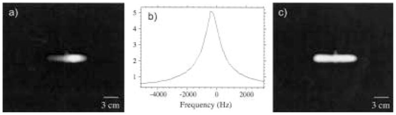
Example of coil response correction for a 3He image of a cylindrical cell (with a small side stem) obtained at B0 = 3.9 mT, Larmor frequency of 127 kHz, and using a tuned receive coil with Q ~100. This results in a coil response with a width ~1.5 kHz across the image space. The acquired spectral width ~16.67 kHz. a) Raw image. b) Coil response function, expanded to the frequency range of the cropped FOV image shown in a). The profile was acquired with a single RF pulse and dead time <100 μs before the sample was placed in the coil. c) Corrected image obtained after each row of the raw image was divided by the response function below it. This image has a uniform signal intensity across the cell and a flat noise floor. Image acquisition parameters are the same as for Figure 8.
The postprocessing method was adequate for the initial images obtained on the system, but the method is subject to several sources of error that would need to be better understood before more quantitative MR experiments can be performed. In particular, it is assumed that the external noise sources and the RF amplification are not changing in time across the bandwidth; if this is not the case, the weighing scheme no longer follows the coil response profile. This method also fails to address attenuation in off-center slice selection where the spins are off-resonance, which was seen during tests with 3He cells. Instead, it may be advantageous to pursue a more direct, hardware-based approach, such as Q-spoiling the receive coil. This would avoid the above problems associated with postprocessing correction; however, Q-spoiling increases the overall coil noise, lowering SNR. Furthermore, it can be difficult to achieve a low Q in a high-inductance, low-frequency coil while matching a specific preamp input impedance, especially if it is relatively low (e.g., 50 Ω). High-field NMR does not suffer from the same problem due to their much higher operating frequencies— high-Q coils will still yield coil responses that are wider than the imaging bandwidths, which, like the low-field system, are tens of Kilohertz wide. Another alternative is to narrow the imaging bandwidth of the system, which is possible if B0 homogeneity is improved.
Finally, improvements in imaging speed can boost imaging quality and increase the number of images or slices obtained under a single breath-hold. The low-field imager used a longer TE as compared with those used on clinical scanners; this was necessary to obtain comparable spatial resolution with the planar gradients, which were weaker than conventional systems and thus required longer pulse times. This led to lower SNR given the short . An actively shielded gradient coil set would provide greater gradient field strength without increasing inductance and limiting ramp-up speed. More critical, however, were limitations in TR, which did not impact image SNR but made images vulnerable to motion artifacts (25). Poor heat dissipation in the planar gradient panels necessitated TR ≥ 100 ms between each phase-encode row acquisition. Modifications to gradient coil design and the implementation of forced air or water cooling would result in significantly greater heat dissipation and hence the ability to reduce image acquisition times by up to a factor of five.
CONCLUSION
We have constructed a prototype very-low-field human scale imager based on simple resistive electromagnets, home-built planar gradient coils, surplus electronics, and NMR components. This open-access system was successfully used to obtain in vivo 3He images of human lungs at both the supine and upright postures with a resolution of 4 × 8 mm and an SNR of ~30.
The development of this system required us to consider noise reduction, signal detection and processing, and hardware design problems unique to open-access, Kilohertz-range 3He MRI operation. The improvements discussed above should be taken into account in similar future-generation systems for imaging performance to approach that available in conventional clinical scanners.
Acknowledgments
The authors acknowledge support from NASA grants NAG9-1166 and NAG9-1489, NIH grants HL67784 and RR14297, and the University of New Hampshire and the Smithsonian Institution. We are grateful to Professor David Cory (MIT) for the Faraday cage donation, and to Outlaw Audio for the audio amplifier.
References
- 1.Walker TG, Happer W. Spin-exchange optical pumping of noble-gas nuclei. Rev Mod Phys. 1997;69:629–642. [Google Scholar]
- 2.Nacher PJ, Leduc M. Optical-pumping in 3He with a laser. Journal De Physique. 1985;46:2057–2073. [Google Scholar]
- 3.Leawoods JC, Yablonskiy DA, Saam B, Gierada DS, Conradi MS. Hyperpolarized He-3 gas production and MR imaging of the lung. Concepts Magn Reson. 2001;13:277–293. [Google Scholar]
- 4.Moller HE, Chen XJ, Saam B, Hagspiel KD, Johnson GA, Altes TA, et al. MRI of the lungs using hyperpolarized noble gases. Magn Reson Med. 2002;47:1029–1051. doi: 10.1002/mrm.10173. [DOI] [PubMed] [Google Scholar]
- 5.Mills GH, Wild JM, Eberle B, Van Beek EJ. Functional magnetic resonance imaging of the lung. Br J Anaesth. 2003;91:16–30. doi: 10.1093/bja/aeg149. [DOI] [PubMed] [Google Scholar]
- 6.Rizi RR, Lipson DA, Dimitrov IE, Ishii M, Roberts DA. Operating characteristics of hyperpolarized 3He and arterial spin tagging in MR imaging of ventilation and perfusion in healthy subjects. Acad Radiol. 2003;10:502–508. doi: 10.1016/s1076-6332(03)80059-4. [DOI] [PubMed] [Google Scholar]
- 7.Salerno M, Altes TA, Brookeman JR, de Lange EE, Mugler JP., III Dynamic spiral MRI of pulmonary gas flow using hyperpolarized 3He: preliminary studies in healthy and diseased lungs. Magn Reson Med. 2001;46:667–677. doi: 10.1002/mrm.1244. [DOI] [PubMed] [Google Scholar]
- 8.Wild JM, Paley MN, Kasuboski L, Swift A, Fichele S, Woodhouse N, et al. Dynamic radial projection MRI of inhaled hyperpolarized 3He gas. Magn Reson Med. 2003;49:991–997. doi: 10.1002/mrm.10477. [DOI] [PubMed] [Google Scholar]
- 9.Saam BT, Yablonskiy DA, Kodibagkar VD, Leawoods JC, Gierada DS, Cooper JD, et al. MR imaging of diffusion of 3He gas in healthy and diseased lungs. Magn Reson Med. 2000;44:174–179. doi: 10.1002/1522-2594(200008)44:2<174::aid-mrm2>3.0.co;2-4. [DOI] [PubMed] [Google Scholar]
- 10.Salerno M, de Lange EE, Altes TA, Truwit JD, Brookeman JR, Mugler JP., III Emphysema: hyperpolarized helium 3 diffusion MR imaging of the lungs compared with spirometric indexes—initial experience. Radiology. 2002;222:252–260. doi: 10.1148/radiol.2221001834. [DOI] [PubMed] [Google Scholar]
- 11.Deninger AJ, Eberle B, Ebert M, Grossmann T, Hanisch G, Heil W, et al. 3He-MRI-based measurements of intrapulmonary PO2 and its time course during apnea in healthy volunteers: first results, reproducibility, and technical limitations. NMR Biomed. 2000;13:194–201. doi: 10.1002/1099-1492(200006)13:4<194::aid-nbm643>3.0.co;2-d. [DOI] [PubMed] [Google Scholar]
- 12.Rizi RR, Baumgardner JE, Ishii M, Spector ZZ, Edvinsson JM, Jalali A, et al. Determination of regional VA/Q by hyperpolarized 3He MRI. Magn Reson Med. 2004;52:65–72. doi: 10.1002/mrm.20136. [DOI] [PubMed] [Google Scholar]
- 13.Tseng CH, Wong GP, Pomeroy VR, Mair RW, Hinton DP, Hoffmann D, et al. Low-field MRI of laser polarized noble gas. Phys Rev Lett. 1998;81:3785–3788. doi: 10.1103/PhysRevLett.81.3785. [DOI] [PubMed] [Google Scholar]
- 14.Parra-Robles J, Cross AR, Santyr GE. Theoretical signal-to-noise ratio and spatial resolution dependence on the magnetic field strength for hyperpolarized noble gas magnetic resonance imaging of human lungs. Med Phys. 2005;32:221–229. doi: 10.1118/1.1833593. [DOI] [PubMed] [Google Scholar]
- 15.Glenny RW, Lamm WJ, Albert RK, Robertson HT. Gravity is a minor determinant of pulmonary blood flow distribution. J Appl Physiol. 1991;71:620–629. doi: 10.1152/jappl.1991.71.2.620. [DOI] [PubMed] [Google Scholar]
- 16.West JB. Importance of gravity in determining the distribution of pulmonary blood flow. J Appl Physiol. 2002;93:1888–1889. doi: 10.1152/japplphysiol.00459.2002. author reply 1889–1891. [DOI] [PubMed] [Google Scholar]
- 17.Chang H, Lai-Fook SJ, Domino KB, Schimmel C, Hildebrandt J, Robertson HT, et al. Spatial distribution of ventilation and perfusion in anesthetized dogs in lateral postures. J Appl Physiol. 2002;92:745–762. doi: 10.1152/japplphysiol.00377.2001. [DOI] [PubMed] [Google Scholar]
- 18.Fichele S, Woodhouse N, Swift AJ, Said Z, Paley MNJ, Kasuboski L, et al. MRI of helium-3 gas in healthy lungs: posture related variations of alveolar size. J Magn Reson Imaging. 2004;20:331–335. doi: 10.1002/jmri.20104. [DOI] [PubMed] [Google Scholar]
- 19.Wong GP, Tseng CH, Pomeroy VR, Mair RW, Hinton DP, Hoffmann D, et al. A system for low field imaging of laser-polarized noble gas. J Magn Reson. 1999;141:217–227. doi: 10.1006/jmre.1999.1904. [DOI] [PubMed] [Google Scholar]
- 20.Owers-Bradley JR, Fichele S, Bennattayalah A, McGloin CJ, Bowtell RW, Morgan PS, Moody AR. MR tagging of human lungs using hyperpolarized 3He gas. J Magn Reson Imaging. 2003;17:142–146. doi: 10.1002/jmri.10226. [DOI] [PubMed] [Google Scholar]
- 21.Durand E, Guillot G, Darrasse L, Tastevin G, Nacher PJ, Vignaud A, et al. CPMG measurements and ultrafast imaging in human lungs with hyperpolarized helium-3 at low field (0.1 T) Magn Reson Med. 2002;47:75–81. doi: 10.1002/mrm.10047. [DOI] [PubMed] [Google Scholar]
- 22.Venkatesh AK, Zhang AX, Mansour J, Kubatina L, Oh CH, Blasche G, et al. MRI of the lung gas-space at very low-field using hyperpolarized noble gases. Magn Reson Imaging. 2003;21:773–776. doi: 10.1016/s0730-725x(03)00178-4. [DOI] [PubMed] [Google Scholar]
- 23.Bidinosti CP, Choukeife J, Tastevin G, Vignaud A, Nacher PJ. MRI of the lung using hyperpolarized 3He at very low magnetic field (3 mT) MAGMA. 2004;16:255–258. doi: 10.1007/s10334-004-0035-y. [DOI] [PubMed] [Google Scholar]
- 24.Bidinosti CP, Choukeife J, Nacher PJ, Tastevin G. In vivo NMR of hyperpolarized 3He in the human lung at very low magnetic fields. J Magn Reson. 2003;162:122–132. doi: 10.1016/s1090-7807(02)00198-2. [DOI] [PubMed] [Google Scholar]
- 25.Mair RW, Hrovat MI, Patz S, Rosen MS, Ruset IC, Topulos GP, et al. 3He lung imaging in an open access, very-low-field human magnetic resonance imaging system. Magn Reson Med. 2005;53:745–749. doi: 10.1002/mrm.20456. [DOI] [PubMed] [Google Scholar]
- 26.Rosen MS, Chupp TE, Coulter KP, Welsh RC, Swanson SD. Polarized Xe-129 optical pumping/spin exchange and delivery system for magnetic resonance spectroscopy and imaging studies. Rev Sci Instrum. 1999;70:1546–1552. [Google Scholar]
- 27.Callaghan PT. Principles of nuclear magnetic resonance microscopy. New York: Clarendon Press, Oxford University Press; 1991. [Google Scholar]
- 28.Morgan PS, Conolly S, Mazovski A. Design of uniform field biplanar magnets. Scientific Meeting of the International Society for Magnetic Resonance in Medicine; Toronto, Canada. 1997. p. 1447. [Google Scholar]
- 29.Rosen MS, Tsai LL, Mair RW, Walsworth RL. Design of an optimized open-access human-scale MRI magnet for orientational lung study. Scientific Meeting of the International Society for Magnetic Resonance in Medicine; Kyoto, Japan. 2003. p. 749. [Google Scholar]
- 30.Hrovat MI, Hersman FW, Patz S, Mair RW, Walsworth RL. Signal correction for narrow-bandwidth coils. Scientific Meeting of the International Society for Magnetic Resonance in Medicine; Toronto, Canada. 2003. p. 1053. [Google Scholar]