Abstract
This work concerns the design, the synthesis, and the characterization of the N-butyl-N-ethylpiperidinium N,N-bis(trifluoromethane)sulfonimide (PP24TFSI) ionic liquid (IL). To impart Li-ion transport, a suitable amount of lithium N,N-bis-(trifluoromethane)sulfonimide (LiTFSI) is added to the IL. The Li–IL mixture displays ionic conductivity values on the order of 10−4 S cm−1 and an electrochemical stability window in the range of 1.8–4.5 V vs Li+/Li. The voltammetric analysis demonstrates that the cathodic decomposition gives rise to a passivating layer on the surface of the working electrode, which kinetically extends the stability of the Li/IL interface as confirmed by electrochemical impedance spectroscopy measurements. The LiTFSI–PP24TFSI mixture is incorporated in a poly(vinylidene fluoride-co-hexafluoropropylene) matrix to form various electrolyte membranes with different LiTFSI–PP24TFSI contents. The ionic conductivity of all the membranes resembles that of the LiTFSI–IL mixture, suggesting an ionic transport mechanism similar to that of the liquid component. NMR measurements demonstrate a reduction in the mobility of all ions following the addition of LiTFSI to the PP24TFSI IL and when incorporating the mixture into the membrane. Finally, an unexpected but potentially significant enhancement in Li transference number is observed in passing from the liquid to the membrane electrolyte system.
The growing large-scale production of batteries all over the world is mainly due to the increasing demand for energy-storage and portable devices. Focusing on the purpose of achieving maintenance-free, high energy density battery systems, the lithium secondary batteries have become the most attractive candidates.1 With respect to the state-of-the-art of such devices, however, further improvements are required, especially in terms of cycling performances and safety. The presence of a highly reactive Li metal as the anode material requires the use of very stable electrolyte solvents. Moreover, the volatility of such solvents is a serious drawback when considering the scaling-up of the battery systems, and the presence of liquids requires special battery pack sealing to prevent leakage. To circumvent safety concerns, research has pursued the implementation of advanced electrolyte solvents. From this viewpoint, ionic liquids (ILs), which are nonvolatile, nonflammable molten salts with high ionic conductivity,2,3 are very promising candidates.
Most commonly, ILs based on aliphatic quaternary ammonium cation, such as N,N,N-trimethyl-N-alkylammonium, N-methyl-N-alkylpyrrolidinium, and N-methyl-N-alkylpiperidinium coupled with bis(trifluoromethane)sulfonimide (TFSI), have been tested for lithium battery application.4,5 Far less attention has been so far devoted to piperidinium-based ILs and to the related ionic-liquid-based polymer gel membrane electrolytes (IPGEs). Structural considerations lead to the expectation that these ILs would exhibit a good electrochemical stability,6 a property that is very important for battery applications. This paper focuses on a Li-ion-conducting electrolyte obtained by dissolving a lithium salt, namely, lithium bis(trifluoromethane)sulfonimide (LiTFSI) in N-butyl-N-ethylpiperidinium bis(trifluoromethane)sulfonimide (PP24TFSI). The resulting mixed salt consists of three ions, i.e., the Li ion, the PP24 cation, and the TFSI anion, the latter being identical for both the Li salt and the IL.
Furthermore, the mixed salt is immobilized in a poly(vinylidene fluoride)–hexafluoro propylene (PVdF–HFP) copolymer matrix to obtain types of flexible IPGEs. The IL mixed salt and the related IPGEs are characterized in terms of ion transport and of electrochemical stability. A detailed NMR analysis is also undertaken to determine the long-range ion-transport behavior of all the mobile species. The results are reported in this work.
Experimental
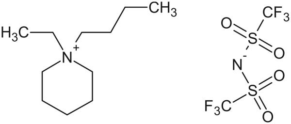
The structures of the IL cation and anion employed in the present study are displayed in Fig. 1. PP24TFSI was prepared according to a two-step procedure, i.e., by quaternization and anion-exchange reactions.6 In the first reaction, N-ethylpiperidine (Aldrich) was reacted with 1-bromobutane (Sigma-Aldrich) by mixing the two reagents in acetonitrile and stirring for 3 days at 50°C. This reaction led to the formation of N-butyl-N-ethylpiperidinium bromide that, after recrystallization, appeared as a white solid. Then, PP24TFSI IL was obtained by a metathesis reaction of the bromide precursor with little excess of LiTFSI in water at room temperature, followed by washing with water to remove impurities. The obtained PP24TFSI was purified by active carbon treatment (Activated Charcoal Norit-type Darco G60, Fluka) and then by using acidic activated alumina (aluminum oxide, activated, acidic, Brockmann I, Sigma-Aldrich). The final yield of this PP24TFSI IL was 68%. The water content (Metrohm KF 831 Coulometer) in the PP24TFSI was revealed to be less than 50 ppm after vacuum drying at 80°C for 12 h and then at 120°C for 24 h; the elimination of residual halides in the PP24TFSI IL was confirmed during the synthesis by the AgNO3 test.
Figure 1.
Structure of the PP24TFSI IL investigated in this work.
To prepare the Li-ion-conducting electrolyte solution, dried LiTFSI (Fluka) was added as a supporting salt to make the LiTFSI–PP24TFSI mixture. The solubility of LiTFSI in the IL was quite low, with the maximum molar fraction limited to 0.4 at room temperature. Therefore, a 0.1 molar fraction (0.2 mol LiTFSI/kg IL) in PP24TFSI IL was chosen as the best option to produce the electrolyte.
The IPGE membranes based on PVdF–HFP (Kynar Flex 2801, Atofina, 100,000 Mw) were prepared by solution casting. The LiTFSI–PP24TFSI mixed salt was added to a PVdF–HFP acetonitrile solution, resulting in a viscous mixture. The weight ratios of the mixed salt to PVdF–HFP were set to 60:40, 70:30, and 80:20, respectively. The mixture was cast on a tray and thermally treated to evaporate the acetonitrile and obtain freestanding IPGE membranes, which, according to the used mixed salt concentrations, were named M60, M70, and M80. All preparation procedures were carried out in an argon-circulating glove box.
The thermal stability of the neat PP24TFSI IL, of the mixed salt, and of the IPGEs was measured by thermal gravimetric analysis (Mettler Toledo TGA/SDTA 851e). The measurements were carried out from 25°C up to 500°C in air environment with a heating rate of 5°C min−1.
The solid–liquid phase transitions of the PP24TFSI IL, the Li–IL mixed salt, and the related IPGE membranes were investigated using differential scanning calorimetry (DSC), performed with a Mettler Toledo DSC 821e instrument. The samples were quenched using liquid nitrogen to −120°C and kept at this temperature for 3 min, heated well above the melting point, and cooled again at a 5°C min−1 scanning rate. Melting points and glass-transition temperatures were taken from the second heating curve.
The ionic conductivity of the various samples was determined by ac impedance spectroscopy (FRA Solartron 1255) with a frequency range from 50 kHz to 1 Hz and an amplitude of 10 mV. The cell used for the room-temperature measurements on the PP24TFSI IL and Li–IL mixed salt consisted of two platinum electrodes immersed in the electrolyte, with a nominal constant of 1.0 cm−1. The conductivity testing cell for the IPGE membranes was configured by sandwiching the membrane (8 mm in diameter and approximately 100 μm thick) between two stainless steel disks using a Teflon spacer and sealing the arrangement inside a Teflon cell. The conductivity measurements were performed between 25 and 110°C on heating and cooling scans.
The electrochemical stability window of the neat PP24TFSI IL and of the mixed salt was measured by cyclic voltammetry (CV, PAR 362 Scanning Potentiostat). Lithium foil (Chemetall Foote) was used as both the counter and reference electrodes, while the working electrode was Super P (SP) carbon deposited on a metallic (e.g., Cu or Al) current collector. The electrode was obtained by mixing SP powder (MMM Carbon Belgium) and the copolymer PVdF–HFP (PVdF 6020, Solvey Solef UHMW), used as a binder, in the weight ratio of 80:20. The separator (Whatman glass microfiber) was soaked with the mixture LiTFSI–PP24TFSI. To determine the electrochemical stability window, the potential was varied from open-circuit voltage (OCV) to 5 V vs Li+/Li in the anodic scan and from OCV to −0.05 V in the cathodic scan, with a rate of 0.2 mV s−1. The electrochemical stability of the IPGEs was evaluated by a CV run on an SP/IPGE/Li cell in which SP acted as the working electrode and a Li disk acted as the counter electrode. The potential was varied from OCV up to 6 V in the anodic scan and from OCV to −0.05 V in the cathodic scan with a rate of 0.2 mV s−1. Cell construction and related manipulations were carried out in an argon atmosphere glove box.
The Li/IL membrane interfacial stability study was conducted by means of ac impedance spectroscopy run on a Li/IPGE/Li symmetrical cell kept under an open-circuit condition at room temperature. The signal amplitude was 5 mV, and the frequency ranged between 100 kHz and 1 Hz.
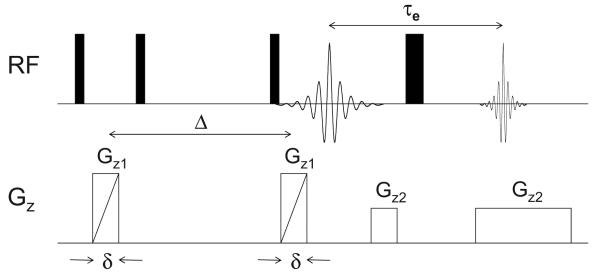
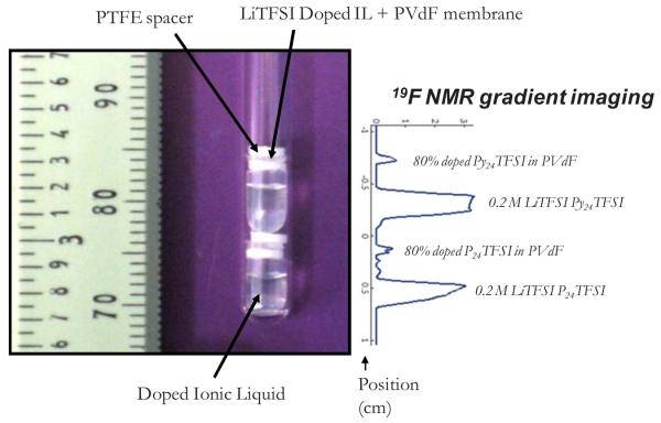
For the NMR measurements, samples of IL, Li–IL mixed salt, and membranes were handled in an Ar glove box and sealed in 5 mm NMR tubes. The membranes were cut into disks 4 mm in diameter. To increase the experimental throughput, a technique was developed to acquire data on several samples simultaneously.1H NMR imaging experiments were performed on a Chemagnetics system with a 7.2 T vertical wide bore magnet and a Nalorac z-spec single-axis gradient probe. The diffusion-weighted imaging pulse sequence illustrated in Fig. 2 proved to be reliable. A stimulated echo block was used to encode diffusive displacements, and an image was obtained with a frequency-encoding gradient during the acquisition of the spin echo generated by the π pulse. Frequency-encoding gradients were usually 14 G cm−1. Typical parameters at 25°C were Gz1 = 7–109 G cm−1, incremented in 15 steps, δ = 1.8 ms, Δ = 20 ms, τe = 5 ms, and eddy current delays of 1 ms following the gradient pulses. To correct for variations in Gz1 across the sample, a map of the relative gradient amplitude at different positions along the gradient-coil axis was generated using the diffusion-weighted imaging pulse sequence and a plug of doped water with known diffusivity at 25.0°C of Dt = 2.3 × 10⁻⁵ cm2 s−1. The actual gradient was calculated from the nominal values, G*, of the applied gradient and the measured diffusivity, D*(z), as . The nominal position z was defined with respect to the center z0 of the gradient field as z − z0 = (1/γ)×[δω(z)/δG*], where δω(z) is the change in resonant frequency at nominal position z with an increase (δG*) in the nominal gradient. During experiments with the stacked membranes, the nominal positions corresponding to peaks in the imaging spectrum of a sample were determined by the same approach employed with the water calibration sample. Once positions were known, correction factors were obtained from the gradient map by interpolation. Figure 3 shows a photograph of the experimental arrangement where as many as two different ILs and their corresponding membranes (total of four distinct samples) could be measured, with their diffusion data spatially encoded. Spin-lattice (T1) measurements were made by using an inversion recovery pulse sequence. The accuracy/reproducibility of the reported D and T1 values were within about 5% variation.
Figure 2.
Diffusion-weighted imaging pulse sequence used for acquiring diffusion data in multiple samples.
Figure 3.
(Color online) NMR tube containing two different IL samples (Py24TFSI is a different IL not discussed in this work) and their corresponding membranes alongside spatially encoded 19F NMR spectra.
Results and Discussion
PP24TFSI IL and LiTFSI–PP24TFSI mixture
The neat IL and the Li/IL solution were characterized in terms of thermal behavior, ionic conductivity, and electrochemical stability.
The thermal stability of the materials was determined by thermo-gravimetric analysis (TGA). The decomposition temperature (Td), here taken as the temperature corresponding to 10% weight loss, was 381°C for the neat PP24TFSI IL and 374°C for the LiTFSI–PP24TFSI mixture (see Table I). The isothermal gravimetric analysis (data not shown) performed on both the PP24TFSI IL and the Li-IL mixture demonstrated that these electrolytes are thermally stable for several hours even at 110°C.
Table I.
Physicochemical properties of the PP24TFSI IL prepared in this work (water content <50 ppm).
| Acronym |
Tg (°C) a |
Tc1 (°C) b |
Tc2 (°C) b |
Tm1 (°C) c |
Tm2 (°C) c |
Td (°C) d |
σ (mS cm−1)e |
Electrochemical window (V vs Li+/Li) |
|---|---|---|---|---|---|---|---|---|
| PP24TFSI | −74 | −40 | −16 | 2 | 11 | 381 | 0.77 | 1.8–4.5 |
| LiTFSI–PP24TFSI | −84 | - | - | - | 5 | 374 | 0.56 | 1.5–4.5 |
Glass-transition temperature determined by DSC on heating.
Crystallization temperature determined by DSC on heating.
Melting point determined by DSC on heating.
Decomposition temperature determined by TGA.
Conductivity at 25°C.
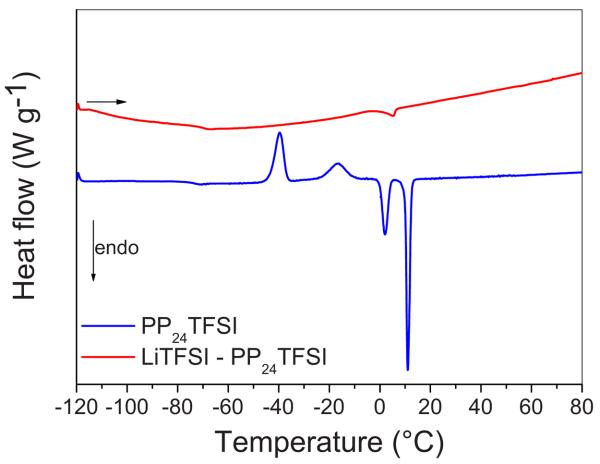
The DSC curves for the PP24TFSI IL and for the Li–IL mixture showed glass-transition temperatures at −74 and −84°C, respectively (see Fig. 4), which is evidence of one of the most significant features of the IL materials, i.e., the tendency to exhibit glass-forming characteristics. The PP24TFSI IL shows evidence of two crystalline domains, characterized by two exothermic peaks corresponding to cold crystallization and two endothermic peaks related to the melting transitions (see Table I). The final melting entropy for this IL is 33.8 J K−1 mol−1, a value typically associated with the ionic plastic crystals based on the large flexible anion TFSI (ΔS = 40 J K−1 mol−1) having high degrees of rotational freedom.7,8 The mixture LiTFSI–PP24TFSI does not show the transitions detected for the neat IL except for a minor peak corresponding to melting at 5°C. The change in the thermal behavior between the PP24TFSI IL and the Li–IL mixture is due to the relatively strong coordination of the TFSI anions by the Li ions.9 The thermal results, as well as the conductivity and electrochemical stability results (see below), are summarized in Table I.
Figure 4.
(Color online) DSC curves of the PP24TFSI IL and of the LiTFSI–PP24TFSI mixture; second heating scan; rate: 5°C min−1.
As a consequence of the strong ion coordination, the ionic conductivity of the LiTFSI–PP24TFSI mixture is lower than that of the neat PP24TFSI IL. The room-temperature ionic conductivity values detected before and after the addition of LiTFSI to the PP24TFSI IL are 0.77 and 0.56 mS cm−1, respectively (see Table I). These conductivity values satisfy the requirements desirable for the application in lithium batteries. As will be discussed later in the context of the NMR results, the main effect of the ion association is to increase the viscosity of the mixed salt, as confirmed by the observed decrease in diffusivity following the LiTFSI addition.
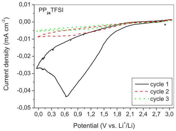
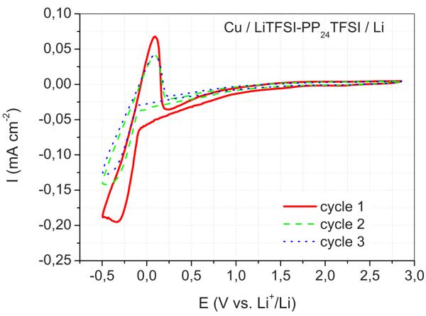
The cathodic electrochemical stability of the PP24TFSI-based electrolytes was studied by CV run on a cell using an SP carbon working electrode and Li both as counter and reference electrodes. Apparent cathodic limits of 1.8 V for the neat PP24TFSI IL and of 1.5 V for the mixture LiTFSI–PP24TFSI were obtained (see Table I). These limits are associated with the reduction of the electroactive species of the mixture, presumably the PP24TFSI IL cationic species,10 although the reduction of the TFSI anion cannot be excluded.11 The cathodic electrochemical stability window of the IL reported in this paper appears to be poorer than that of conventional electrolyte solutions based on organic solvents. Nonetheless, the measurement has been performed in the most conservative conditions, i.e., by using SP as the test electrode. This particular electrode has a large surface area, on which the decomposition reactions of the electrolyte are expected to be particularly enhanced. By simply switching the testing electrode from carbon to copper, the electro-chemical stability windows of the IL-based electrolyte appears wider, showing the lithium plating at −0.3 V vs Li. This result confirms the validity of our strategy, even though further optimization is obviously required.
In Fig. 5 we show the cyclic voltammogram obtained on a lithium cell using the LiTFSI–PP24TFSI mixture as the electrolyte. We observe that no oxidation peaks appear in the reverse scan, which means that the reductive process is irreversible. Furthermore, the peak detected on the first scan vanishes upon cycling. We can then deduce that the products of the initial LiTFSI–PP24TFSI reduction deposit on the electrode surface, forming a solid electrolyte interphase (SEI), which inhibits further electrolyte decomposition. Such a passivating action, which kinetically widens the electro-chemical cathodic stability, has already been observed and reported.12
Figure 5.
(Color online) CV of an SP carbon electrode in a cell using a LiTFSI–PP24TFSI mixture as electrolyte. Li counter and reference electrodes. Scan rate: 0,2 mV s−1. Water content: <50 ppm. Room temperature.
The decomposition limits depend on the type of working electrodes used. Figure 6 shows the CV carried out on a cell using the same LiTFSI–PP24TFSI electrolyte solution and the same Li reference and counter electrodes but a different working electrode, here a copper foil rather than an SP carbon film. The results demonstrate that, passing from SP to Cu, the response changes considerably. Indeed, the lithium deposition process occurs prior to the decomposition of PP24TFSI, showing a lithium plating peak at around −0.3 V vs Li+/Li, followed by a corresponding lithium stripping peak at 0.1 V vs Li+/Li. The reversibility of the Li plating/stripping process clearly indicates that the Li+ ions are mobile in the mixed salt and that lithium is capable of dissolution into and deposition from this solution. Copper is used as a current collector in lithium ion batteries; thus, the result of Fig. 6 is of practical relevance.
Figure 6.
(Color online) CV of a copper electrode in a cell using a LiTFSI–PP24TFSI mixture as electrolyte. Li counter and reference electrodes. Scan rate: 0.2 mV s−1. Room temperature.
IPGEs
IL-based IPGE membranes have been successfully developed by Fuller et al. by using imidazolium salts combined with a (PVdF–HFP) polymer.13,14 In this work we have extended the study by considering types of IPGEs containing different amounts of LiTFSI–PP24TFSI. Three samples having LiTFSI–PP24TFSI/PVdF–HFP weight ratios of 60:40, 70:30, and 80:20, respectively, and accordingly named M60, M70, and M80, respectively, were prepared, as previously stated in the Experimental section.
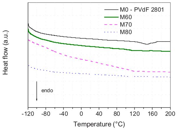
Figure 7 shows DSC curves of these IPGE membranes, with data collected during the second heating step. As a reference, the trace obtained from a recast Li–IL-mixture-free PVdF–HFP membrane (named M0) is also reported. This reference membrane shows a melting peak at 147°C, while the melting point of the IPGE membranes significantly decreases and is even suppressed upon progressive increase in LiTFSI–PP24TFSI content. This suggests the occurrence of interactions among Li salt, IL, and PVdF–HFP, as effectively confirmed by NMR spectroscopy (see the related discussion further on). There is no sign of phase transition from −120°C up to the melting point of the IPGEs (when observed) or even up to 200°C. Moreover, the TGA analysis (data not shown) demonstrates that the thermal stability of the IPGE membranes is extended well above 350°C, clearly indicating that no component is volatile inside these membranes.
Figure 7.
(Color online) DSC traces of the LiTFSI–PP24TFSI/PVdF–HFP membranes having different IL mixture contents.
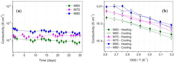
The ionic conductivity of the three IPGE membranes was monitored over a time period of 30 days at room temperature. Figure 8a shows that the conductivity of all the LiTFSI–PP24TFSI/PVdF–HFP membranes is on the order of magnitude of 10−4 S cm−1 at room temperature and is stable in time. This value is lower than that of the pure IL. Although the ion transport in the membrane relies on the IL–LiTFSI electrolyte confined into the PVdF–HFP matrix, one has to realize that the polymer confinement may affect the value of the overall conductivity.
Figure 8.
(Color online) (a) Stability plot of the conductivity values of the three LiTFSI–PP24TFSI/PVdF–HFP membranes prepared in this work over a period of time of 30 days at room temperature. Argon atmosphere. (b) Arrhenius plot of the ionic conductivity of the LiTFSI–PP24TFSI/PVdF–HFP membranes with different IL solution contents. Temperature range: 40–110°C on heating and cooling scans. Argon atmosphere.
Figure 8b shows the temperature dependence of the ionic conductivity of the membranes in the form of Arrhenius plots. The ionic conductivity remains reasonably high over the whole temperature range investigated (40–110°C). The highest conductivity is that of the M80 membrane, which reaches values on the order of 10−3 S cm−1 above 50°C and of 10−2 S cm−1 at 110°C. The regular increase in the conductivity upon heating confirms that neither physical transition nor segregation phenomena occur in the temperature range investigated. A small hysteresis is observed at low temperature, possibly indicating the thermal memory effect of the PVdF–HFP polymer.
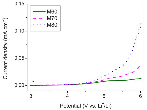
Similar to the case of the neat IL mixture, it is important to determine the stability window of the membranes as well. Figure 9 shows the anodic scan of a typical CV of an SP electrode in lithium cells having IPGEs containing different Li–IL contents as electrolytes. The IPGE membranes display anodic limit potentials increasing with the amount of the contained mixed salt. This behavior is difficult to explain; one can tentatively associate it with the progressively lower amount of the LiTFSI–PP24TFSI mixture available for the electrode reaction, in turn due to the confinement effects, which are greater in the less concentrated IPGEs. The cathodic scans are similar to those observed for the LiTFSI–PP24TFSI mixed salt (see Fig. 5), and thus, it is assumed that the considerations on the formation of SEI films on the electrode surface hold also in the membrane case.
Figure 9.
(Color online) Cycling voltammetry of an SP carbon electrode in a cell using a LiTFSI–PP24TFSI/PVdF–HFP membrane having differing IL solution contents as electrolytes. Li counter and reference electrodes. Scan rate: 0.2 mV s−1. Room temperature.
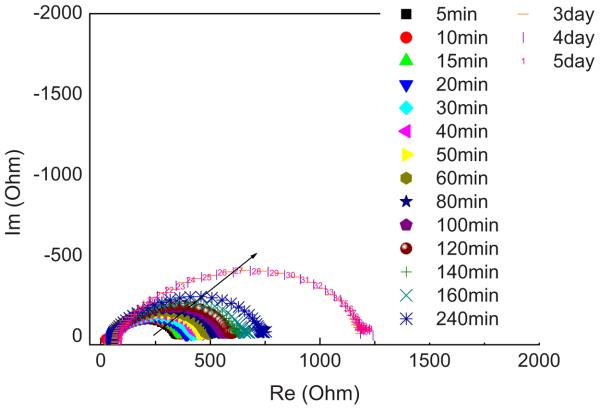
To shed more light on the development of the SEI layer, impedance spectroscopy was run on symmetrical Li/IPGE/Li cells using the M80 membrane as the preferred IPGE electrolyte and kept under open-circuit conditions. Figure 10 shows the time evolution of the response. The appearance of all the spectra is that of a depressed semicircle arising from the convolution of different contributions. The width of the semicircle is related to the resistance of the interface, as supported by the capacitance values (i.e., on the order of 10−7 F) associated with the equivalent circuit components used to fit the spectra. The overall spectra may be fitted with an equivalent circuit composed of a series of parallel RQ elements. In most cases, it is possible to detect the convolution of two semicircles. Considering the frequency and capacitance values, it is possible to attribute this multi-semicircle response to the presence of a multilayer SEI. As a first approximation, one can say that the overall width of the convoluted semicircles is related to the resistance of the interphase IL electrolyte/electrode, in turn depending on the thickness of the SEI layer. The increase in the width of the semicircles, followed by the stabilization around an equilibrium value, means that the SEI progressively forms upon time of storage at open-circuit conditions to eventually passivate the electrode.
Figure 10.
(Color online) Time evolution of the impedance spectra of a symmetrical Li/M80/Li cell upon storage time.
Indeed, Fig. 10 clearly shows that the semicircle diameter grows during the initial 240 min and then decreases after 3 days to finally reach an equilibrium value. We may reasonably assume that the resistance of the interface is directly linked with the thickness of the passivating layer. Therefore, the trend of Fig. 10 confirms the formation and growth of a stable SEI layer on the lithium electrode surface, finally supporting the information obtained from the volta-mmetry results.
In the characterization of IL-based membranes, an important aspect is the determination of the degree of release of the liquid electrolyte component upon pressure or aging. The stability of the conductivity over time as demonstrated in Fig. 8a is by itself a good sign of the stability of the IPGE membranes. The IL-retaining capability of the membranes was further checked by mechanical tests. As a representative example, the M80 membrane was subjected to a constant pressure (0.6 atm at 27°C), and the consequent weight loss, imputed to the leakage of the IL solution, was monitored vs time (data not shown). The weight of the IPGE membrane steeply decreases during the first 2 h and then remains at a constant value. A total mass loss of about 20% was detected after 40 h of treatment. This result suggests that 80% of the initial IL mixture is stably retained in the membrane backbone, possibly by confinement in the membrane structure, whereas the released 20% may be assumed to comprise a free liquid component.
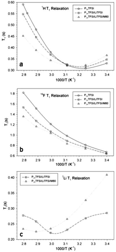
Further investigation of the state of “free vs bound” IL has been performed by NMR analysis. This technique has been employed in characterizing the long-range ion transport of all mobile species by measurement of self-diffusion coefficients as well as more localized motional processes accessed through T1 measurements in both IL–Li salt mixtures15,16 and their corresponding membranes.17,18 Arrhenius plots of spin-lattice relaxation (T1) in neat PP24TFSI, the mixture LiTFSI–PP24TFSI, and the M80 LiTFSI–PP24TFSI membrane for the three nuclei (1H, 19F, and 7Li) contained in the PP24 cation, anion, and Li, respectively are displayed in Fig. 11a-c, respectively. The proton NMR relaxation behavior in Fig. 11a is consistent with successively increasing local hindrance to cation motion, which may include translational and rotational (including CH3 groups) motion, as the LiTFSI is added and the mixture is incorporated into the membrane. The mixed salt has higher viscosity, which also accounts for the lower ionic conductivity of the mixture compared to the pure IL, and, of course, interactions with the membrane suppress the motion further. The position of the T1 minimum, which occurs when the molecular correlation time is approximately equal to the reciprocal of 2π times the NMR frequency, clearly shifts toward higher temperatures in the membrane. There is also a smaller shift toward higher temperatures in the salt mixture compared to the pure IL. At temperatures above the T1 minimum, the value of T1 is inversely proportional to the correlation time, and this is reflected in the successively increasing values of T1 for the pure IL to the salt mixture to the membrane. A similar trend is observed for the 19F relaxation results displayed in Fig. 11b, where it is assumed that all values shown are above the T1 minimum. The 7Li data in Fig. 11c exhibit a significant shift toward higher temperatures in the T1 minimum from the IL–salt mixture to the membrane, again indicating that short-time-scale motion is strongly affected by the membrane–salt interaction. The observed relaxation recovery profiles of the membrane were well described by a single relaxation process, which does not support the existence of a significant amount of “free” liquid in the M80 sample, despite the previously discussed weight loss under pressure result. That is, even the portion of liquid that is easily removable is still subject to interaction with the membrane structure or in rapid equilibrium with the more “tightly” held liquid. The investigation of the interactions between the IL and the PVdF polymer matrix has been deepened by IR and Raman spectroscopy. These data will be presented elsewhere.9
Figure 11.
Arrhenius plots of spin-lattice relaxation (T1) in neat PP24TFSI, LiTFSI–PP24TFSI, and M80 LiTFSI–PP24TFSI membrane for (a) 1H, (b) 19F, and (c) 7Li (for the latter two samples).
The measurement of self-diffusion coefficients is important because it gives information on the effective mobility of the Li ion over that of all mobile species moving into the IPGE systems. This allows the evaluation of the Li transference number, which is a key parameter, hard to determine by usual electrochemical methods in electrolyte systems based on ILs. It has to be pointed out that the determination of the transport properties in IL-based electrolytes is not an easy task due to the presence of more than one electroactive species and to the still unclear phenomena occurring at the electrode interfaces.
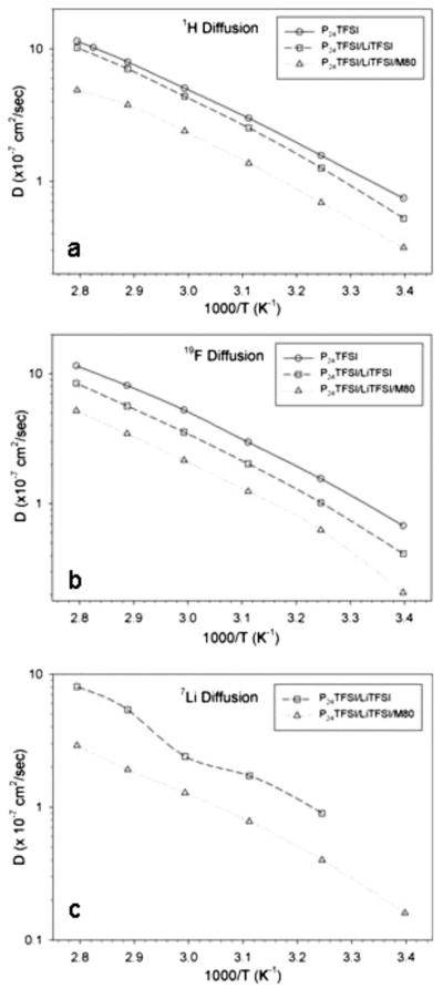
Diffusion data are presented in Arrhenius plots in neat PP24TFSI, the mixed salt LiTFSI–PP24TFSI, and the M80 LiTFSI–PP24TFSI membrane for the three nuclei, 1H, 19F, and 7Li corresponding to the PP24 cation, the TFSI anion, and Li, respectively, in Fig. 12a-c. The long-range transport results are largely consistent with expectations as well as the short-range motions probed by T1 measurements discussed previously. The PP24 diffusion in Fig. 12a decreases with the addition of Li salt and membrane incorporation, as does the TFSI diffusion in Fig. 12b and the Li diffusion in Fig. 12c. It is instructive to compare D values of all three mobile ions in the materials, and representative data at 25°C are listed in Table II, along with selected ratios. In all three samples, PP24 and TFSI diffusivities, D are comparable but with slightly higher cation D, which is often observed in similar systems.15-18 Li diffusivity in the liquid mixture tends to be lower than the PP24 and TFSI diffusivity values because of strong association with the TFSI anions, which can be disrupted by adding solvating agents such as ethylene carbonate.18 The ratio of TFSI to Li diffusion is about a factor of 2 in the mixture liquid, whereas it drops to about unity in the membrane. The specific mechanism that causes this is unknown at this time, but the net result is a significant increase in Li transference number in the IPGE membrane, which has important implications for practical applications.
Figure 12.
Arrhenius plots of self-diffusion coefficients (D) in neat PP24TFSI, LiTFSI–PP24TFSI, and M80 LiTFSI–PP24TFSI membrane for (a) 1H (PP24 cation), (b) 19F (anion), and (c) 7Li (for the latter two samples).
Table II.
Self-diffusion coefficient values of 1H, 19F, and 7Li nuclei, and related selected ratios. Representative values at 25°C. Multisample imaging.
| D(1H)a | D(19F)a | [D(1H)/D(19F)] | D(7Li)a | [D(19F)/D(7Li)] | |
|---|---|---|---|---|---|
| Neat IL (PP24TFSI) | 0.67 | 0.63 | 1.06 | - | - |
| Doped IL (0.2 M LiTFSI) | 0.50 | 0.45 | 1.12 | 0.24 | 1.9 |
| 80% doped IL membrane | 0.21 | 0.18 | 1.21 | 0.19 | 0.95 |
(×10−7 cm2/sec) All data acquired nominally at 25°C
Conclusion
A chemically and electrochemically stable IL, consisting of TFSI anion with N-ethyl-N-butylpiperidinium cation, PP24TFSI, was synthesized and characterized. The addition of the LiTFSI salt to the PP24TFSI IL provides a Li-ion-conducting electrolyte with good conductivity and an electrochemical stability window at a level that makes this IL a promising electrolyte for Li batteries.
IPGEs with desirable properties were readily synthesized by mixing the LiTFSI–PP24TFSI salt with a PVdF–HFP copolymer. As shown by the thermal analyses, the Li–IL mixture acts as a plasticizer for the polymer matrix, suppressing the crystallinity of the resulting IPGE membranes. This conformation leads to ionic conductivity values on the order of 10−4 S cm−1 at room temperature, linearly increasing with the LiTFSI–PP24TFSI content. In the IPGE membrane richest in the IL solution (80 wt % with respect to the total weight of the membrane sample), the ionic conductivity expectedly increases with temperature, reaching 10−2 S cm−1 at 110°C. Both electrochemical investigation and mechanical tests suggest that IL-based membranes can also be considered as valid candidates for the development of advanced lithium polymer batteries.
The characterization of the membranes was completed by running NMR measurements of all three mobile species via 1H, 7Li, and 19F. The results confirmed the expected influences on ion mobility from increased viscosity of the mixed salt solution and incorporation of the liquid into the membrane, on both short-time scales probed by T1 and long-time scales probed by D. The NMR measurements suggest that less tightly bound liquid evidenced from mechanical leaching is still strongly associated with the membrane host structure or in equilibrium with the more tightly bound liquid. Finally, an unexpected but potentially technologically significant enhancement in Li transference number is observed in going from the liquid to the membrane.
Acknowledgments
The work carried out at Hunter College was supported by grants from the U.S. Air Force Office of Scientific Research and the Office of Naval Research and an infrastructure grant from the National Institutes of Health (no. RR 03037). The work carried out at La Sapienza was supported by the Italian Ministry of University and Research (MIUR) under the PRIN 2007 Project.
References
- 1.Tarascon J-M, Armand M. Nature (London) 2001;414:359. doi: 10.1038/35104644. [DOI] [PubMed] [Google Scholar]
- 2.Ohno H. Electrochemical Aspects of Ionic Liquids. John Wiley & Sons; New York: 2005. [Google Scholar]
- 3.Fernicola A, Scrosati B, Ohno H. Ionics. 2006;12:95. [Google Scholar]
- 4.Sakaebe H, Matsumoto H. Electrochem. Commun. 2003;5:594. [Google Scholar]
- 5.Howlett PC, MacFarlane DR, Hollenkamp AF. Electrochem. Solid-State Lett. 2004;7:A97. [Google Scholar]
- 6.MacFarlane DR, Meakin P, Sun J, Amini N, Forsyth M. J. Phys. Chem. B. 1999;103:4164. [Google Scholar]
- 7.MacFarlane DR, Forsyth M. Adv. Mater. (Weinheim, Ger.) 2001;13:957. [Google Scholar]
- 8.MacFarlane DR, Meakin P, Sun J, Amini N, Forsyth M. J. Phys. Chem. B. 1999;103:4164. [Google Scholar]
- 9.Martinelli A, Matic A, Fernicola A, Scrosati B. To be published.
- 10.Buzzeo MC, Evans RG, Compton RG. ChemPhysChem. 2004;5:1106. doi: 10.1002/cphc.200301017. [DOI] [PubMed] [Google Scholar]
- 11.Howlett PC, Brack N, Hollenkamp AF, Forsyth M, MacFarlane DR. J. Electrochem. Soc. 2006;153:A595. [Google Scholar]
- 12.MacFarlane DR, Forsyth M, Howlett PC, Pringle JM, Sun J, Annat G, Neil W, Izgorodina EI. Acc. Chem. Res. 2007;40:1165. doi: 10.1021/ar7000952. [DOI] [PubMed] [Google Scholar]
- 13.Fuller J, Breda AC, Carlin RT. J. Electrochem. Soc. 1997;144:L67. [Google Scholar]
- 14.Fuller J, Breda AC, Carlin RT. J. Electroanal. Chem. 1998;459:29. [Google Scholar]
- 15.Hayamizu K, Aihara Y, Nakagawa H, Nukuda T, Price WS. J. Phys. Chem. B. 2004;108:19527. [Google Scholar]
- 16.Byrne N, Howlett PC, MacFarlane DR, Forsyth M. Adv. Mater. (Weinheim, Ger.) 2005;17:2497. [Google Scholar]
- 17.Nicotera I, Oliviero C, Henderson WA, Appetecchi GB, Passerini S. J. Phys. Chem. B. 2005;109:22814. doi: 10.1021/jp053799f. [DOI] [PubMed] [Google Scholar]
- 18.Ye H, Huang J, Xu JJ, Khalfan A, Greenbaum SG. J. Electrochem. Soc. 2007;154:A1048. doi: 10.1149/1.2779962. [DOI] [PMC free article] [PubMed] [Google Scholar]


