Abstract
Ionic liquids thermodynamically compatible with Li metal are very promising for applications to rechargeable lithium batteries. 1-methyl-3-propylpyrrolidinium bis(trifluoromethanesulfonyl)imide (P13TFSI) is screened out as a particularly promising ionic liquid in this study. Dimensionally stable, elastic, flexible, nonvolatile polymer gel electrolytes (PGEs) with high electrochemical stabilities, high ionic conductivities and other desirable properties have been synthesized by dissolving Li imide salt (LiTFSI) in P13TFSI ionic liquid and then mixing the electrolyte solution with poly(vinylidene-co-hexafluoropropylene) (PVDF-HFP) copolymer. Adding small amounts of ethylene carbonate to the polymer gel electrolytes dramatically improves the ionic conductivity, net Li ion transport concentration, and Li ion transport kinetics of these electrolytes. They are thus favorable and offer good prospects in the application to rechargeable Li batteries including open systems like Li/air batteries, as well as more “conventional” rechargeable lithium and lithium ion batteries.
As is well known, Li is the most electropositive and lightest metal, and thus has the greatest theoretical specific capacity of 3860 Ah/kg.1,2 This has attracted worldwide efforts of researchers and manufacturers to develop advanced battery technologies based on lithium. To date, the rechargeable lithium ion battery has already been one of the best choices in view of specific capacity and cycle stability.1 However, rechargeable lithium metal batteries with even higher specific capacities are still unavailable in the market, especially lithium/air batteries which possess the highest theoretical specific energy (as high as 13,000 Wh/g, excluding the oxygen from the air). Conventional Li/air batteries based on aqueous electrolytes suffer from fast capacity loss due to corrosion of lithium by water and are also nonrechargeable. Abraham and Jiang first reported a rechargeable lithium/oxygen cell using organic polymer gel electrolytes and demonstrated its advantages such as an all solid state design, rechargeablity and a high capacity.3 Read studied the effect of electrolyte and air cathode formulation on the electrochemical properties of an Li/O2 organic electrolyte cell and found that electrolyte composition has the largest effect on discharge capacity and rate capability.4 Both groups incorporated common organic solvents in the electrolyte, i.e., ethylene carbonate (EC), propylene carbonate (PC), 1,2-dimethoxyethane, diethyl carbonate (DEC), dimethyl carbonate, γ-butyrolactone, tetrahydrofuran, or tetrahydropyran.3,4 The highly reactive lithium metal cannot, however, be thermodynamically compatible with common organic solvents. The fact that the air cathode of Li/air cells must be open to the ambient environment poses considerable additional challenges in improving the properties of the electrolytes being used, such as meeting the requirements of little to no volatility, moisture insensitivity and air stability. Our efforts are concerned with developing suitable electrolytes with good lithium interface stability, high electrochemical stability, high ion conductivity and low volatility for not only lithium/air batteries but also the more “conventional” rechargeable lithium and lithium ion batteries.
Recently, the resurgence of ionic liquids, especially those that are air stable, has drawn the attention of researchers in the electrochemical field.5-13 Ionic liquids are room-temperature molten salts typically consisting of bulky, asymmetric organic cations and inorganic anions. The important attributes of ionic liquids include a wide electrochemical window, high ionic conductivity, and high thermal stability.8,14 In addition, it is evident that employing ionic liquid as a solvent can safely enhance the performance of lithium based cells, particularly large-scale batteries and Li/air batteries, because of the ionic liquid's nonflammable and nonvolatile nature. Webber and Blomgrem have enumerated the advantages of ionic liquids for lithium-ion and related batteries.8 More significantly, some ionic liquids with a certain combination of cation and anion have recently been reported as being electrochemically stable in the presence of lithium metal, as opposed to conventional organic solvents. Ionic liquids that have been determined as such include quaternary ammonium salts,9,15,16 pyrrolidinium salt,9,10,17,18 piperidinium salts,9 and some multisubstituted imidazolium salts19,20 as well. Furthermore, most investigated ionic liquids of these salts consist of the bis(trifluoromethanesulfonyl)imide anion (TFSI−). Coulombic cyclic efficiency of Li plating/stripping close to 100% has been obtained from using these ionic liquids as electrolyte solvents.9,10,18 A Li/LiCoO2 cell prototype containing the piperidinium-TFSI salt9 and another containing quaternary ammonium-TFSI salt16 both show very good performance and large utilization of the positive electrode material at the same time.9 Li/LiFePO4 and Li/V2O5 cells incorporating polymer gel electrolytes consisting of poly(ethylene oxide), LiTFSI and pyrrolidinium-TFSI salt also demonstrated exceptional performance (at 40°C).21,22 Concerning the characteristics of electrochemical stability and ionic conductivity, the work of this paper will screen out pyrrolidinium-TFSI salt as a promising solvent and focus on the application of this ionic liquid to the electrolyte of lithium batteries.
The investigated Li-salt/ionic liquid electrolyte consists of three ions, i.e., Li ion, the cation of the ionic liquid and the same anion from both the Li salt and ionic liquid. It needs to be emphasized that in this system, all ions being transported contribute to the ionic conductivity, but only Li ion transport is relevant for the charge/discharge of Li (ion) batteries. Unfortunately, nuclear magnetic resonance (NMR) studies have shown that the self-diffusion coefficients of the cation of the ionic liquid are equal to or higher than those of the anion depending on the anion.23 In the system of LiBF4/EMIBF4, the smallest Li ion diffuses slowest, while the EMI cation always diffuses fastest.24 There is still no clear explanation of this phenomenon. Hayamizu et al. proposed that the Li+ and form ion complexes and diffuse together while EMI+ becomes relatively freer to move.24 Be that as it may, the transport of other ions may lead to cell polarization, which will reduce high rate performance of the batteries. It is very important to increase Li ion transport in these new Li-salt/ionic liquid complexes. Interestingly, it was found that the zwitterion 1-butylimidazolium-3-(n-butanesulfonate), which is a type of salt similar to an ionic liquid but with a higher melting point (152°C), can improve lithium-ion transport dramatically in the LiTSFI/1-methyl-3-propylpyrrolidinium imide (P TFSI) electrolyte.25,26 In this paper, we investigated the effect of ethylene carbonate (EC) as an ion dissociation enhancer to improve Li ion transport due to its high dielectric constant and relatively good thermal stability (EC has a boiling point above 240°C). In fact, ethylene carbonate is used as a cosolvent in commercial electrolytes for lithium ion batteries because it can provide an effective protective layer on the surface of graphite to prevent continuous electrolyte reduction.1 The formed solid electrolyte interphase film also prevents the co-intercalation of the organic cation of the ionic liquid, another potential problem in the application of ionic liquid.27,28 It is reasonable to expect the addition of EC will also facilitate the formation of a protective film on the carbon black of the cathode, allowing Li ions to pass through while protecting the catalyst layer on the air-electrode side from the ionic liquid organic cation.
Currently most research regarding the applications of ionic liquids is on lithium-ion or lithium batteries based on liquid electrolyte systems, yet polymer electrolytes are preferable for suppressing dendrite growth and meeting all-solid state requirements of the cells. It has been noted that ionic liquids have strong interactions with many polymers.10,29-32 Shin et al. have reported that the dry solid polymer electrolyte consisting of high molecular weight polyethylene oxide (PEO), LiTFSI and P13TFSI reaches an ionic conductivity of ∼10−4 S/cm at 20°C, almost two orders of magnitude higher than that of ionic-liquid-free PEO-LiTFSI electrolyte.10 However, the hydrophilicity of PEO will preclude its application to the Li/air cell in which PEO will be in direct contact with moisture. PVDF-based polymer electrolytes are expected to be highly anodically stable when one considers the strongly electron-withdrawing functional group (-C-F) that is present.33 A copolymer of vinylidene fluoride with hexafluoropropylene (PVDF-HFP) is capable of trapping large amounts of liquid electrolyte while retaining the advantage of PVDF by sustaining sufficient mechanical integrity for the processing of freestanding films. Moreover, PVDF-HFP possesses good hydrophobicity. In fact, PVDF-HFP is the polymer choice for Bellcore's plastic Li-ion batteries.34 Furthermore, dimensionally stable, elastic, flexible, polymer gel electrolytes with desirable mechanical strength and properties can be readily synthesized by mixing ionic liquids with PVDF-HFP.29,30,35
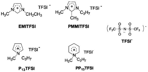
In this paper, P13TFSI has first been screened out as a promising solvent from four ionic liquids (as shown in Scheme 1), i.e., 1-ethyl-3-methylimidazolium bis(trifluoromethanesulfonyl)imide (EMITFSI), 1-propyl-2,3-dimethylimidazolium bis(trifluoromethanesulfonyl)imide (PMMITFSI), 1-methyl-3-propylpyrrolidinium bis(trifluoromethanesulfonyl)imide (P13TFSI), and 1-methyl-3-propylpiperidinium bis(trifluoromethanesulfonyl)imide (PP13TFSI) through cyclic voltammetry testing. Then, polymer gel electrolyte membranes with different LiTFSI/P13TFSI concentration have been prepared through blending with PVDF-HFP polymer. Ionic conductivity and ion transport properties as a function of LiTFSI concentration have been characterized for these membranes. The effect of small amounts of EC on the lithium ion transport and other electrochemical properties are also discussed subsequently in the 1 M LiTFSI/xEC + (1 − x)P13TFSI/PVDF-HFP complex systems. Thermal analysis and pulsed gradient spin-echo (PGSE)-NMR was undertaken to understand the mechanism of ionic transport in these polymer gel electrolytes. Moreover, preliminary solid-state, thin-film Li/oxygen cells were constructed using the investigated polymer gel electrolyte membrane and their performances were analyzed.
Scheme 1.
Molecular structure of four investigated ionic liquids.
Experimental
Materials
1-methylimidazole, 1,2-dimethylimidazole, N-methylpyrrolidine, N-methylpiperidine, 1-bromopropane, 1-bromoethylane, anhydrous acetonitrile, anhydrous ethylene carbonate, anhydrous acetone were purchased from Sigma-Aldrich and used as received. Battery grade lithium foil is from FMC. Poly(vinylidene fluoride-co-hexafluoropropylene) (PVDF-HFP), Kynar 2801, was kindly provided by Atofina Chemicals. Lithium bis(trifluoromethanesulfonyl)imide (LiTFSI) was kindly provided by Minnesota Mining and Manufacturing Company and dried under vacuum at 90°C for 24 h prior to use.
Synthesis of ionic liquids
All hydrophobic ionic liquids were prepared according to a two-step procedure, quaternization and then anion-exchange reaction.5,35,36 The synthesis of P13TFSI has been shown in Scheme 2 as an example. First N-methyl pyrrolidine is reacted with the 1-bromopropane to obtain N-methyl-N-propyl pyrrolidinium bromide. Then room temperature ionic liquids were obtained by anion exchange reactions of N-methyl-N-propyl pyrrolidinium bromide with lithium imide. The ionic liquid product was purified by recrystallization, active carbon treatment, and then dried under vacuum at 70°C for 24 h before using.
Scheme 2.
Schematic illustration of the synthesis process of P13TFSI ionic liquid.
Preparation of polymer gel electrolyte membranes
Polymer gel electrolyte membranes were prepared by the solution casting method. First, LiTFSI salt was dissolved into ionic liquid or ionic liquid/EC solution to form liquid electrolyte with proper lithium salt concentration. The resulting ionic liquid solution was then mixed with 7.5 wt % PVDF-HFP acetone solution resulting in a viscous mixture. The weight ratio of the Li salt/ionic liquid (w/EC) solution to PVDF-HFP was set at 7:3. Finally the mixture solution was cast over a Teflon tray, and the acetone was subsequently evaporated under vacuum to result in a freestanding polymer gel electrolyte membrane. All preparation steps were carried out in an argon-circulating glove box.
Measurements
The ionic conductivity of ionic liquids and Li salt/ionic liquid solutions was measured by Oaklon conductivity meter (with nominal cell constant of 1.0). Electrochemical characterizations were carried out by using the Solartron 1287 electro-chemical interface combined with 1260 impedance/gain-phase analyzer. The electrochemical stability windows of ionic liquids and Li salt/ionic liquid (w/EC) solutions were determined by cyclic voltammetry test with a scan rate of 10 mV/s while using Pt as both the working electrode and the counter electrode and AgCl/Ag as the reference electrode. The AgCl/Ag electrode was prepared by electrochemically depositing an AgCl layer on a polished Ag rod from saturated NaCl solution. The temperature dependence of ionic conductivity was determined by ac impedance with a frequency range from 10 Hz to 1 MHz with amplitude of 5 mV. A conductivity testing cell was set up by sandwiching the polymer gel electrolyte membrane (12.7 mm in diameter and approximately 150 μm thick) between two stainless steel (SS) disks and sealing the configuration inside of the Hohsen Test Cell (Hohsen Corporation, Japan). The measurements were performed from 80 to −20°C using an environment chamber (B-M-A, Inc.) as the temperature control. Cyclic voltammetry tests were carried out by using either a symmetric cell, Li/polymer gel electrolyte/Li, or an asymmetric cell, SS/ polymer gel electrolyte/Li, to demonstrate the reversible equilibrium of Li/Li+. The scanning rate was 10 mV/s between 1.0 and −1.0 V vs Li+/Li, in which the SS working electrode was a freshly polished stainless steel disk. The electrochemical stability of the polymer gel electrolyte was evaluated by means of a linear potential sweep using the SS/polymer gel electrolyte/Li cell, in which SS acts as the working electrode and a Li disk acts as both the counter electrode and reference electrode. The scanning range is from an open circuit potential to 6.5 V vs Li+/Li with a scan rate of 1.0 mV/s.
The thermal stability of polymer gel electrolytes was measured by thermal gravimetric analysis (Perkin-Elmer TGA7). The measurement was carried out from room temperature to 200°C under N2 flow environment with a heating rate of 10°C/min. Differential scanning calorimetry (DSC) was performed with a Q1000 DSC System from TA Instruments, Inc. The measurement was carried out from −50°C to 150°C at a heating and cooling rate of 10°C/min. A cooling-heating-recooling cycle was carried out first, and DSC data were collected during the subsequent heating step.
1H, 7Li, and 19F NMR techniques were used to investigate the ion transport of polymer gel electrolytes over the temperature range of 20 to 120°C. Here 1H, 7Li, and 19F were detected as NMR-sensitive nuclei corresponding to the P13, Li, and TFSI ion components of the polymer gel electrolyte. NMR measurements were performed on a Chemagnetics CMX-300 spectrometer in conjunction with a JMT superconducting magnet of field strength 7.1 T. The Larmor frequencies for 1H, 7Li, and 19F were 300.0, 116.9, and 283.2 MHz, respectively. Measurements were carried out on ∼500 mg samples which were inserted and packed into 5 mm Pyrex tubes in a very low humidity (<5 ppm) dry box (VAC). The Pyrex tubes were flame sealed under vacuum to prevent any contamination from outside air and moisture. Self-diffusion coefficients of different ions (P13, Li, and TFSI) were obtained by the pulse gradient spin-echo (PGSE) technique 37 (PGSE-NMR), which uses the Hahn spin-echo pulse sequence but with the inclusion of gradient pulses. Gradient strengths (g) ranged from 10 to 200 G/cm. Pulse widths were ∼5 μs for 7Li and ∼10 μs for 1H and 19F. A Nalorac Z-Spec gradient probe and also a Doty gradient probe were used to facilitate diffusion measurements. The experimental parameters Δ (gradient delay) and δ (gradient duration) ranged from 45 to 100 ms and 15 to 25 ms, respectively, for 7Li, and from 25 to 350 ms and 1 to 7 ms, respectively, for 19F and 1H. Gradient calibration was accomplished using pure distilled water at 25°C at which D = 2.29 × 10⁻⁵ cm2/s. The frequency reference used for both 7Li and 19F was a saturated LiCF3SO3 aqueous solution, and distilled water served as the 1H reference. The value of the self-diffusion coefficient was calculated by plotting the echo attenuation factor (E) according 38 to Eq. 1 for a single diffusing species in an isotropic medium38
| [1] |
where γ is the gyromagnetic ratio, g is the gradient strength, δ is the duration of the gradient pulse, and Δ is the interval between the gradient pulses.
Fabrication and testing of Li/O2 cells
The Li/oxygen cell was fabricated by sandwiching a LiTFSI/P13TFSI/PVDF-HFP polymer gel electrolyte membrane between a Li foil and an air electrode. The air electrode was prepared by spraying a catalyst/carbon black ink onto wet-proof E-TEK carbon paper followed by heat-treatment. The prepared air electrode consisted of 2.12 wt % cobalt phthalocyanine, 82.88 wt % Vulcan carbon black and 15 wt % polytetrafluoroetheylene as binder. The Li anode side of the cell was sealed, and the air electrode side open to flowing oxygen (flow rate about 25 mL/min). The current density used for discharge/charge was 0.05 mA/cm2 at the air electrode. The cutoff voltage for discharge and charge were 2.0 and 4.1 V, respectively.
Results and Discussion
Screening of the ionic liquids
As mentioned in the introductory section, in most cases, the investigated Li-salt/ionic liquid electrolyte has the same anion in both the Li salt and ionic liquid. This is due to solubility issues. In our preliminary study, it was found that the solubility of Li salt in the ionic liquid incorporating the same anion is much higher than those systems with different anions. For example, N-ethyl-methyl imidazolium trifluoromethanesulfonate (EMITf) can dissolve only 0.3 mol/L of LiTFSI, EMITFSI can dissolve around 0.2 mol/L of lithium trifluoromethanesulfonate (LiTf), whereas EMITFSI can dissolve up to 2 mol/L of LiTFSI. Moreover, the solubility of LiTf in the EMITf is also rather low, about 0.3 mol/L, which highlights the advantage of using highly dissociable LiTFSI salt. In this paper, our study begins with four hydrophobic ionic liquids, all with TFSI anion, i.e., EMITFSI, PMMITFSI, P13TFSI and PP13TFSI as shown in Scheme 1, to select a suitable ionic liquid for further study.
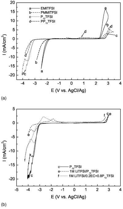
Having a wide electrochemical stability window is a prerequisite property of the solvent for lithium batteries, especially good cathodic stability in view of highly active lithium. Cyclic voltamogram tests have been carried out to determine the stability window for different kinds of ionic liquids. Figure 1a shows the electrochemical stability windows of these four ionic liquids. The abnormal current fluctuation of P13TFSI at potentials more negative than −3.5 V (vs AgCl/Ag) may be due to the fast and unstable decomposition of the ionic liquid. The weak anodic current around 0.9 V for PP13TFSI in the forward scan may be due to some impurity or a decomposition product resulting from the reduction reaction of the ionic liquid. Figure 1b gives the electrochemical window of pure ionic liquid P13TFSI, 1 M LiTFSI/P13TFSI electrolyte solution, and electrolyte solution with 20 wt % EC (percentage corresponding to total weight of EC and P13TFSI). The cathodic stability limit and anodic stability limit are defined as the potential point corresponding to cathodic current density or anodic current density up to 1 mA/cm2, respectively. The values of them are listed in Table I. From best to worst, the order of cathodic stability is: PP13TFSI > P13TFSI > PMMITFSI > EMITFSI. The anodic stability from best to worst is: P13TFSI > PP13TFSI > PMMITFSI > EMITFSI. Both PP13TFSI and P13TFSI have very wide electrochemical stability windows with values around 5.9 V. As far as the cathodic stability limit is concerned, these values are −3.25 and −3.07 V vs AgCl/Ag for PP13TFSI and P13TFSI, respectively. Figure 1b shows Li+/Li reduction at −3.11 V vs AgCl/Ag in the 1 M LiTFSI/P13TFSI and at −3.04 V vs AgCl/Ag in the 1 M LiTFSI/0.2EC + 0.8P13TFSI electrolyte. If we include the possibility of over-potential delay of Li+/Li reduction in the investigated electrolyte, the redox potential of Li+/Li would be more positive than −3.04 V vs AgCl/Ag in the investigated ionic liquids. Both PP13TFSI and P13TFSI are therefore stable enough for Li+/Li reduction reaction. It is clearly shown in Fig. 1a that the reduction stability of EMITFSI is insufficient for Li batteries, about 1.1 V positive against Li/Li+. This result is consistent with the literature.9,39 It was reported that the proton at the C2-position of imidazolium cation is subject to chemical reduction.20 Alkyl substitution of this proton can improve its reduction ability as reported by Sutto et al.20 Here PMMITFSI shows improved reduction stability, but still cannot meet the reduction limitation of Li+/Li.
Figure 1.
Electrochemical stability windows of ionic liquids or electrolyte solution: (a) cyclic voltammograms for different ionic liquids; (b) cyclic voltammograms for P13TFSI, 1 M LiTFSI/P13TFSI, and 1 M LiTFSI/0.2EC + 0.8P13TFSI.
Table I.
Electrochemical stability limit and ionic conductivity of different ionic liquids and electrolyte solutions.
| Ionic liquids | σ (mS/cm) |
Ecathodic (V vs AgCl/Ag) |
Eanodic (V vs AgCl/Ag) |
|---|---|---|---|
| EMITFSI | 8.52 | −1.90 | 2.31 |
| PMMITFSI | 2.55 | −2.16 | 2.38 |
| P13TFSI | 3.62 | −3.07 | 2.82 |
| PP13TFSI | 1.73 | −3.25 | 2.68 |
| 1 M LiTFSI/P13TFSI | - | −3.11 | 2.73 |
| 1 M LiTFSI/0.2EC + 0.8P13TFSI | - | −3.04 | 2.52 |
As shown in Fig. 1b adding LiTFSI slightly increases the reduction stability of P13TFSI, the lithium deposition process occurs before the decomposition of P13TFSI. The peak around −3.50 V vs AgCl/Ag is due to a Li plating reaction, which has a corresponding stripping peak at −1.82 V vs AgCl/Ag. The following current increase at a potential below −3.76 V vs AgCl/Ag may be ascribed to the decomposition of the ionic liquid itself. There are also two shoulders appearing at ∼−2.47 V and ∼−1.44 V vs AgCl/Ag corresponding to a Li stripping process. Multi stripping peaks may imply different characteristics of Li layers plated on the Pt rod (0.5 mm diameter). However, the continuous reduction current increase below −3.07 V vs AgCl/Ag for P13TFSI can be attributed to its decomposition and no anodic peak shows up at potentials above −3.0 V vs AgCl/Ag. Adding a small amount of EC does not change the reduction stability of electrolyte significantly but slightly decreases the anodic stability of the electrolyte as shown in Fig. 1b. More interestingly, adding a small amount of EC also more than doubles the Li plating/stripping peak current density (also around −3.50 V vs AgCl/Ag), which demonstrates that the addition of EC can enhance the Li ion transport in the electrolyte. The stripping of lithium in the electrolyte with EC is also facilitated. The stripping peak appears around −2.66 V vs Ag+/Ag with one shoulder at −2.23 V vs Ag+/Ag, thus showing lower over-potentials than those of the electrolyte without EC.
LiTFSI/P13 TFSI/PVDF-HFP polymer gel electrolytes
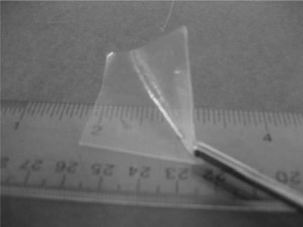
Dimensionally stable, elastic, flexible, polymer gel electrolytes with desirable mechanical strength and other desirable properties can be readily synthesized by mixing Li salt/ionic liquids with PVDF-HFP. Polymer gel electrolyte membranes with different LiTFSI concentrations show similar morphologies and mechanical properties. Figure 2 gives a representative picture of 1 M LiTFSI/P13TFSI/PVDF-HFP polymer gel electrolyte membrane. PVDF-HFP copolymer matrix retains the LiTFSI/P13TFSI very well, up to 70 wt %, and the liquid electrolyte in the membranes is difficult to squeeze out under pressure. Good mechanical properties of the PVDF-HFP based electrolyte membrane also benefit the battery assembly process.
Figure 2.
Photograph of 1 M LiTFSI/P13TFSI/PVDF-HFP polymer gel electrolyte membrane.
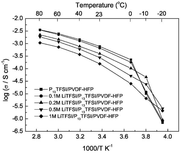
Figure 3 shows the temperature dependence of the ionic conductivity of P13TFSI/PVDF-HFP and xM LiTFSI/P13TFSI/PVDF-HFP (x = 0.1, 0.2, 0.5, and 1) membranes. LiTFSI/P13TFSI/PVDF-HFP polymer gel electrolytes show good ionic conductivities above 0°C albeit lower than those of P13TFSI/PVDF-HFP. For example, the ionic conductivities of 0.5 M LiTFSI/P13TFSI/PVDF-HFP reach 0.05 mS at 0°C, 0.27 mS at room temperature, and larger than 1.1 mS above 60°C. These data are two orders of magnitude higher than conductivity values of PEO-Li salt complex, and these membranes uphold the same advantage of containing no volatile solvents.
Figure 3.
Temperature dependence of the ionic conductivity of P13TFSI/PVDF-HFP and xM LiTFSI/P13TFSI/PVDF-HFP (x = 0.1, 0.2, 0.5, and 1) membranes.
As seen in Fig. 3, the higher Li salt concentration leads to lower ionic conductivity of the membrane at the temperatures above 0°C. The temperature dependent ionic conductivity of the polymer gel electrolyte with pure ionic liquid (i.e., P13TFSI/PVDF-HFP) is very similar to that of the polymer gel electrolyte with very low LiTFSI concentration (0.1 M LiTFSI/P13TFSI/PVDF-HFP). These results are widely reported for liquid electrolytes, the explanation being that adding Li salt increases the viscosity of the liquid electrolyte. For the polymer gel electrolyte membrane containing the highest content of liquid electrolyte, here P13TFSI ionic liquid functions as both a plasticizer for the polymer matrix (note: LiTFSI can also plasticize the polymer due to its high charge delocalization feature) and a solvation medium for electrolyte salt. PVDF-HFP provides mechanical support and dimensional stabilization through polymer chain entanglements and/or chemical cross-linking. Polymer (gel) electrolytes possess both the cohesive properties of solids and the diffusive transport properties of liquid electrolytes 33 at the same time due to their unique hybrid network structure. Figure 3 also shows that temperature dependent ionic conductivities (log σ vs 1/T) of the polymer gel electrolytes exhibit non-Arrhenius VTF behavior at temperatures ≥0°C. This behavior is similar to that of PEO-based lithium ion conducting polymer gel electrolytes, in which ion transport is related to the segmental motion of the polymer chain.40 At temperatures below 0°C, however, the polymer gel electrolyte without Li salt or with lower Li salt concentration (≤0.5 mol/L) shows an abrupt conductivity drop. The presence of more Li salt concentration moves this sudden drop to a lower temperature. This phenomenon becomes insignificant for the polymer gel electrolyte with 1 mol/L LiTFSI in P13TFSI. The conductivity drop may result from the ionic liquid or Li salt/ionic liquid undergoing a freezing transition. Additional evidence of this can be observed from DSC measurements, which will be discussed later. The drop in conductivity indicates that incorporating LiTFSI can suppress the recrystallization/melting process of Li salt/ionic liquid, as has been found for Zn salt/ionic liquid complex.35 To extend the application temperature range of Li batteries, it is preferable to use a high Li salt concentration.
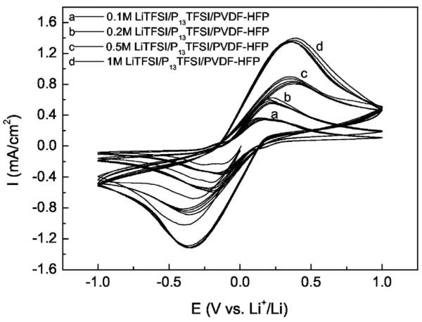
Figure 4 shows the cyclic voltammograms of symmetric Li/PGE/Li cells for the membranes with different Li salt concentration. CV test starts with reduction scanning, i.e., Li plating first. The first cycle shows a slightly lower plating current density, which may be due to an activation step and/or the formation of lithium metal. Highly reversible Li plating/stripping at the Li/PGE interface was observed for all membranes after the second cycle. Reversible Li plating/stripping clearly indicate that Li+ ions are mobile in the PGE membranes containing Li salts, and Li is capable of dissolution into and deposition from these membranes. As seen in Fig. 4, the increase of Li salt concentration leads to the increase of plating/stripping peak current densities. The appearance of the current density peak is due to a balance between a high over-potential driving force and the concentration diffusion limit. High peak current densities ensure a high rate discharge/charge capability, so high Li salt concentration in the membrane is beneficial for the rate capability of lithium batteries. Although higher Li salt concentration leads to lower ionic conductivity as shown in Fig. 3, it is surmised that the increase of Li salt concentration improves the Li ion transport number. However, Li salt concentration cannot be too high because it leads to low conductivity due to high ionic association. Furthermore, Li salt cannot dissolve homogeneously in P13TFSI at a concentration above 1.5 mol/L as experimentally observed.
Figure 4.
Cyclic voltammograms of symmetric Li/PGE/Li cells for the xM LiTFSI/P13TFSI/PVDF-HFP (x = 0.1, 0.2, 0.5, and 1) membranes, scan rate: 10 mV/s.
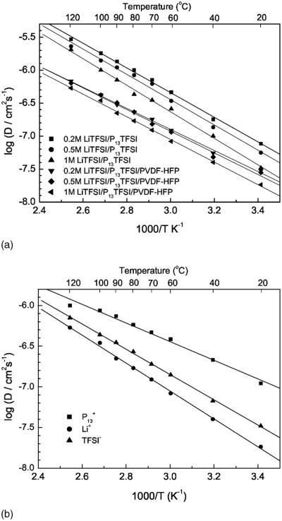
The fundamental understanding of the ionic transport mechanism of Li salt/ionic liquid complex, especially in the polymer gel electrolyte, is still not well understood. NMR has been reported as a powerful method in determining the ionic diffusion coefficient and the degree of ionic association in the liquid system of ionic liquid or Li/EMIBF4.23,24 Arrhenius plots of the self-diffusion coefficient of Li (DLi), both in the Li salt/ionic liquid and in the polymer gel electrolyte membranes with different Li salt concentration, are shown in Fig. 5a. Arrhenius plots of the self-diffusion coefficient of the different ions in the underscored 1 M LiTFSI/P13TFSI/PVDF-HFP polymer gel electrolyte are shown in Fig. 5b. As shown in Fig. 5a, Li+ ions are mobile both in the LiTFSI/P13TFSI solutions and in the membranes blended with PVDF-HFP, although the value of DLi is smaller in the polymer gel electrolytes than in the binary ionic liquids for any specific Li salt concentration. There is a linear relationship between log(DLi) and 1/T for either binary ionic liquid or polymer gel electrolyte in the temperature range of 20–120°C. In both the binary ionic liquids and the corresponding polymer gel electrolytes, increasing the Li salt concentration leads to a decrease in the self-diffusion coefficient of Li ion. The behavior suggests, once again, that an increase of Li salt concentration increases the viscosity of the electrolyte. The investigated LiTFSI/P13TFSI systems follow an inverse correlation between the self-diffusion coefficient of Li ion and viscosity as described by Stokes-Einstein equation23
| [2] |
where k is Boltzmann's constant, T is the absolute temperature, c is a constant, η is the viscosity, and r is the effective hydrodynamic or Stokes radius. The activation energy of Li self-diffusion slightly increases with Li concentration. Also, the results of the binary ionic liquid systems are in agreement with results obtained by Hayamizu and co-workers.24
Figure 5.
Arrhenius plots of the self-diffusion coefficient of Li, P13, and TFSI: (a) self-diffusion coefficient of Li in xM LiTFSI/P13TFSI solution and in xM LiTFSI/P13TFSI/PVDF-HFP membranes (x = 0.2, 0.5, and 1); (b) self-diffusion coefficient of Li, P13, and TFSI in the 1 M LiTFSI/P13TFSI/PVDF-HFP membrane.
Figure 5b compares the self-diffusion coefficient of the different ions in the specified 1 M LiTFSI/P13TFSI/PVDF-HFP polymer gel electrolyte. Unfortunately, the smallest Li ion diffuses the slowest and the biggest organic cation P13 diffuses faster than TFSI, which is similar to results reported in the literature.23,24 These results are, however, somewhat different than results most recently reported by Nicotera et al.,41 who show that TFSI moves faster than P13, and P13 moves faster than Li. Referring to the work of Hayamizu et al.,24 a possible explanation for the observed diffusive behavior in Fig. 5b is that the small Li+ ion has strong attraction with TFSI− anion, and may be coordinated with multiple TFSI− ions at the same time cations are freed from the TFSI− anion. As a result, motion is less encumbered by TFSI− association than Li+. Further study of the ion transport mechanism of these polymer gel electrolytes is under way. From a practical point of view, it is very important to improve the Li ions transport properties so as to improve the rate capability of the lithium batteries because other ions will polarize the electrode. Suppose all ionic species are free, i.e., no ion pairs and no ion association exist, the NMR transference number for Li in the polymer gel electrolyte can be calculated by the following equation24
| [3] |
where N denotes number of charge carriers. In the case of 1 M LiTFSI/P13TFSI/PVDF-HFP, at 20°C, the calculated tLi+,NMR is only 0.034, too low for battery application. Of course, the ion transport mechanism is not the same under NMR testing as under the battery charge/discharge cycling. In the NMR experiment, we attain an average self-diffusion coefficient of the ions and associated ions. In the battery, only net ions contribute to the conductivity. It is important to improve the Li ion transport in these polymer gel electrolytes. Adding EC into the electrolyte should improve the dissociation of Li ion in view of its very high dielectric constant (89.79).42 Moreover, Fig. 1b already shows that adding small amounts of EC more than doubles the Li plating/stripping peak current density. It is worthwhile to study the effect of EC on the performances of this polymer gel electrolyte system.
Effect of EC on the performances of 1 M LiTFSI/P13TFSI/PVDF-HFP
As discussed above, the polymer gel electrolyte with high Li salt content provides high plating/stripping peak current densities, in other words, high concentration of active working ion. In this section, we fix the LiTFSI concentration at 1 mol/L of P13TFSI or of P13TFSI + EC cosolvent (5 wt %, 10 wt %, and 20 wt % of EC in the cosolvent). The content of PVDF-HFP is still fixed at 30 wt % of the total polymer gel electrolyte membrane. The actual calculated percentages of EC in the investigated membranes are then 0 wt %, 2.9 wt %, 5.8 wt %, and 11.6 wt %. The physical appearance of the membranes with EC is the same as the membrane without EC, i.e., freestanding, elastic, flexible, translucent polymer membranes.
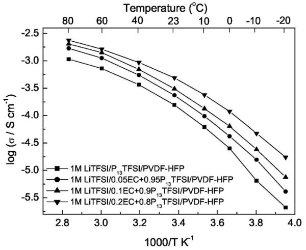
Arrhenius plots of the ionic conductivity of the polymer gel electrolyte with different content of EC are shown in Fig. 6. The ionic conductivity of the polymer gel electrolyte increases with an increase of the EC content. For example, the ionic conductivities of the polymer gel electrolyte with 11.6 wt % EC reaches 0.01 mS/cm at −20°C, 0.5 mS/cm at room temperature and about 1 mS/cm at 40°C. These values are typical of polymer gel electrolytes with common organic solvents PC, EC, DEC, and others.33 The increase in ionic conductivities of the polymer gel electrolytes can be ascribed to the high dielectric constant of EC, which enhances the ionic dissociation of the LiTFSI and P13TFSI and thus improves the concentration of free ions contributing to conduction. Moreover, the value of log(σ) decreases smoothly from 80 to −20°C, i.e., no abrupt dropping occurs, and all plots exhibit VTF behavior. The behavior also reflects that EC functions as a plasticizer in the polymer gel electrolyte.
Figure 6.
Temperature dependence of the ionic conductivity of 1 M LiTFSI/xEC + (1 − x) P13TFSI/PVDF-HFP (x = 0, 0.05, 0.1, and 0.2) membranes.
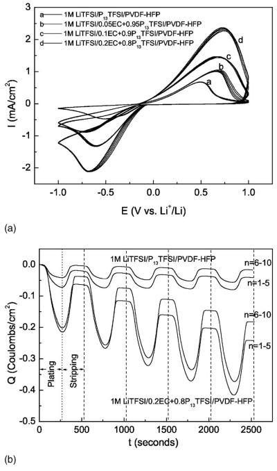
To clearly demonstrate the plating/stripping of Li, polished stainless steel (SS) was implemented as the working electrode of the cyclic voltammogram test cell, with Li foil serving as the counter electrode and reference electrode. Figure 7a shows the cyclic voltammograms of asymmetrical SS/PGE/Li cells for the membranes with different EC content. All polymer gel electrolyte membranes show reversible Li plating/stripping. Adding EC improves the Li plating/stripping current densities. Higher EC content correlates with a higher plating/stripping current density of the polymer gel electrolyte. The highest plating/stripping current densities for the film with highest EC content are 2.0 and 2.2 mA/cm2, respectively, almost a factor of 3 times greater than those values of the membrane without EC. Figure 7b is a plot of the first ten cyclic voltammograms (Li plating/stripping) cycles of the polymer gel electrolyte, shown as charge density vs time. For comparative purposes, only 1 M LiTFSI/0.2EC + 0.8P13TFSI/PVDF-HFP and 1 M LiTFSI/P13TFSI/PVDF-HFP are plotted. For both polymer gel electrolytes, the Coulombic efficiency increases gradually in the initial cycles and reaches a stable efficiency at the sixth cycle. The stable Coulombic efficiency of the 1 M LiTFSI/0.2EC + 0.8P13TFSI/PVDF-HFP is ∼83%, a little lower than that of 1 M LiTFSI/P13TFSI/PVDF-HFP (about 92%). However, there is a continuous increase of the plating charge (Qp) of 1 M LiTFSI/0.2EC + 0.8P13TFSI/PVDF-HFP in the first ten cycles. The Qp of 1 M LiTFSI/P13TFSI/PVDF-HFP, on the other hand, decreases slightly during the first five cycles, and then reaches a constant after the fifth cycle. And the Qp of 1 M LiTFSI/0.2EC + 0.8P13TFSI/PVDF-HFP is almost six times that of the polymer gel electrolyte without EC at the fifth cycle. The Coulombic loss during each plating/stripping cycle may be due to poor contact between interde-posited Li layer on the SS and polymer gel electrolyte, as evidenced by a thin gray-black layer on the SS after dissembling the CV test cell. The formation of SEI film on the SS is also a possible reason and needs to be further investigated. Figures 7a and b clearly demonstrate that adding EC enhances the Li ion transport dramatically.
Figure 7.
Cyclic voltammograms of asymmetrical SS/PGE/Li cells, 1 M LiTFSI/xEC + (1 − x)P13TFSI/PVDF-HFP (x = 0, 0.05, 0.1, and 0.2) membranes [(a) I vs E plots of the 6th to 10th cycles, (b) Q-t plots of the first 10 cycles for selected two polymer gel electrolytes].
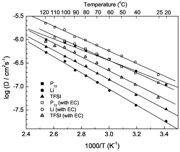
Figure 8 compares the self-diffusion coefficient of different ions (DLi, DP13 and DTFSI) in the 1 M LiTFSI/0.2EC + 0.8P13TFSI/PVDF-HFP and 1 M LiTFSI/P13TFSI/PVDF-HFP polymer gel electrolytes. It is interesting to see that adding EC can remarkably increase the kinetics of Li ion transport. The mobility of Li ions is highest in the membrane with 11.6 wt % EC while they move slowest in the membrane without EC, clearly indicating that adding EC improves the Li ion transference number in the polymer gel electrolyte. The value of DLi of the 1 M LiTFSI/0.2EC + 0.8P13TFSI/PVDF-HFP polymer gel electrolyte is more than three times that of the polymer gel electrolyte without EC. Adding EC also increases the mobility of TFSI ions but has no significant effect on P13 ions.
Figure 8.
Arrhenius plots of the self-diffusion coefficient of Li, P13, and TFSI in the 1 M LiTFSI/P13TFSI/PVDF-HFP and 1 M LiTFSI/0.2EC + 0.8P13TFSI/PVDF-HFP polymer gel electrolyte membranes.
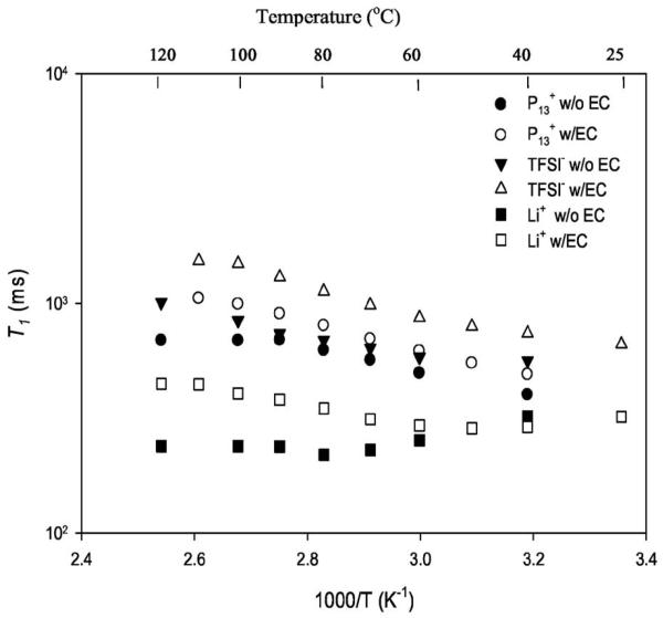
In order to gain additional dynamic information on the effect of EC incorporation, spin-lattice relaxation time (T1) measurements, which are sensitive to rates of molecular/ionic motion occurring in the ∼108 s−1 frequency range, were carried out by use of the inversion recovery method.43 The uncertainties in the values obtained are 3–5%. In the T1 plot shown in Fig. 9, we readily notice that the T1s for the different ions in the polymer gel with EC are higher than the corresponding values in the gel without EC. The only exception to this are the 7Li T1s at low temperature, a point we explore in detail later. The protons associated with the P13 ions do not exhibit a minimum in T1 as this most likely occurs below the lowest temperature of the present set of measurements. Further reduction of motional correlation times at temperatures above the T1 minimum give rise to increasing T1 values. Thus the addition of EC increases the short-range motion of the P13 ion. However, the change in T1 values upon adding EC is still relatively small. The reason for the leveling off of P13 T1 in the gel without EC is not understood. The 19F from the TFSI ions also do not exhibit a clear T1 minimum and, as in the case of P13 indicate enhanced motion (longer T1) with the addition of EC. This effect is still relatively small, although somewhat larger than in the case of P13. In both of these cases, it is likely that rotational mechanisms contribute to relaxation, and the addition of EC apparently enables freer rotation of methyl and trifluoromethyl groups, although the EC effect is a little less pronounced for P13 than for TFSI. Most importantly, from Fig. 9, we observe a minimum occurring for the Li ions at substantially lower temperature for the sample with EC than for the sample without it, providing a clear measure of enhanced motional correlation time upon addition of EC. This is in accord with conductivity and diffusion data (Fig. 6 and Fig. 8).
Figure 9.
Temperature dependence of NMR spin-lattice relaxation measurements of the different ions in 1 M LiTFSI/P13TFSI gels (with and without EC).
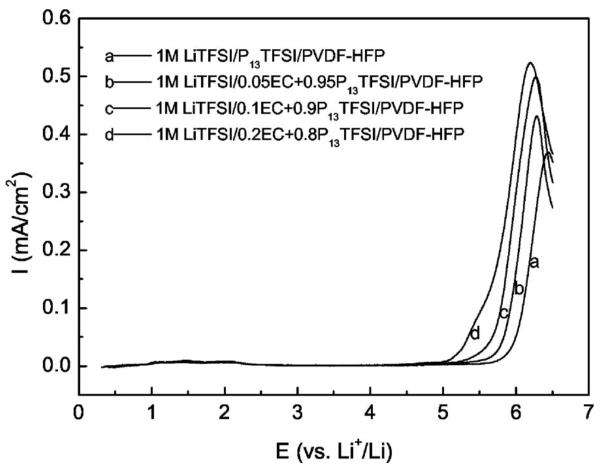
Linear sweep voltammetry was performed on SS/PGE/Li cells to study the electrochemical stability of the membranes with varying content of EC as shown in Fig. 10. All the membranes possess good anodic electrochemical stability. The anodic stability limit (here the potential was set at a current density up to 10 μA/cm2) of 1 M LiTFSI/P13TFSI/PVDF-HFP is as high as 5.75 V vs Li+/Li. Adding EC decreases anodic stability slightly, but all are wide enough for Li/air batteries. In fact, the membrane with highest EC content is still stable up to 5.1 V vs Li+/Li, making this series of polymer gel electrolytes suitable for most high voltage Li intercalation cathode materials, too.
Figure 10.
Linear sweep voltammograms of 1 M LiTFSI/xEC + (1 − x)P13TFSI/PVDF-HFP (x = 0, 0.05, 0.1, and 0.2) membranes using SS/PGE/Li cell; scan rate is 1 mV/s.
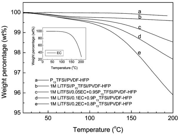
Figure 11 shows TGA results of the membranes containing the ionic liquids or Li salt/ionic liquid with different EC content. There is essentially no weight loss for the membranes with pure ionic liquid and Li salt/ionic liquid without EC when they are heated from room temperature to 200°C, which clearly indicates that no component is volatile inside these membranes. Adding EC slightly decreases the thermal stability of the membranes above 100°C. The weight loss above 100°C is mainly due to the loss of EC as supported by the TGA results of pure EC which is shown in the inset in Fig. 11. The thermal stability of all investigated membranes is still good (weight loss less than 0.5 wt %) below 100°C. The nonvolatility or low volatility of the polymer gel electrolyte is especially important for potential applications in open systems such as solid-state, thin film Li-air batteries.
Figure 11.
TGA of P13TFSI/PVDF-HFP and 1 M LiTFSI/xEC + (1 − x)P13TFSI/PVDF-HFP (x = 0, 0.05, 0.1, and 0.2) membranes.
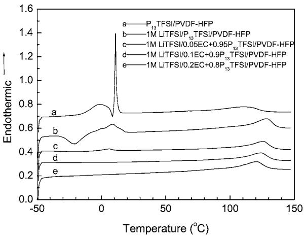
In order to understand the thermal properties as well as interactions among the various components of the polymer gel electrolyte membranes, DSC tests were performed on the polymer membranes containing pure ionic liquids and Li salt/ionic liquid with different EC content. Figure 12 shows DSC curves of the investigated polymer gel electrolyte membranes, with data collected during the second heating step. All membranes show a wide endothermic peak above 100°C which may be ascribed to the melting of polymer. As a reference, the recast PVDF-HFP film has the melting peak at 139.5°C.35 The melting peak for P13TFSI/PVDF-HFP is 110°C which may be due to the plasticization effects of ionic liquid. After adding 1 M LiTFSI, the melting peak of the polymer membrane increases to 128°C. Adding a small amount of EC will decrease the melting peak of the polymer membrane slightly, 126, 124, and 121°C for the polymer membrane with 2.9 wt % EC, 5.8 wt % EC, and 11.6 wt % EC, respectively. This can contribute to the plasticization effect of EC. The EC is well dispersed inside the membranes as evidenced by the lack of an EC melting feature.
Figure 12.
DSC of P13TFSI/PVDF-HFP and 1 M LiTFSI/xEC + (1 − x)P13TFSI/PVDF-HFP (x = 0, 0.05, 0.1, and 0.2) membranes.
As shown in Fig. 12, there is a sharp endothermic peak at 11°C following a wide endothermic peak around 1°C for P13TFSI/PVDF-HFP. The sharp endothermic peak can be ascribed to the melting peak of phase-separated P13TFSI, which is close to the Tm of pure ionic liquid P13TFSI (12°C reported by MacFarlane et al.17 There is no recrystallization peak corresponding to this melting peak for pure ionic liquid shown in Fig. 12 probably due to the test temperature limitation. As reported, there is an exothermic peak around −67°C for pure P13TFSI.17 The metastable phase transformation around −18°C17 for pure P13TFSI does not show up in the investigated membrane either. The wide peak around 1°C can be ascribed to the melting of polymer-solvated P13TFSI because there are only two components in this polymer membrane and recast PVDF-HFP does not show any thermal transform around this temperature.35 There is only one wide endothermic peak for the membrane containing 1 M LiTFSI/P13TFSI at 9°C coupled with a wide exothermic peak around −21°C. This indicates that incorporating LiTFSI improves the solubility of P13TFSI in the PVDF-HFP and makes the whole complex more homogeneous. Adding LiTFSI significantly suppresses the recrystallization process of P13TFSI and decreases the melting of polymer-solvated P13TFSI, reflecting the interaction among Li salt, ionic liquid and PVDF-HFP, as reported in the Zn salt/ionic liquid/PVDF-HFP system.35 It is interesting to see that adding a small amount of EC can further suppress the recrystallization/melting of P13TFSI. As shown in Fig. 12, 2.9 wt % EC decreases the melting of polymer-solvated P13TFSI to 6°C (the small endothermic peak) and totally suppresses the recrystallization process of the membrane. For the membrane with 5.9 wt % EC and 11.6 wt % EC, there is no distinct phase transformation from −45°C to the melting point of polymer gel electrolyte. This feature of the polymer gel electrolyte with EC ≥ 5.8 wt % is particularly advantageous for potential applications of the batteries, such as military and aerospace applications as well as civilian electric and hybrid vehicle applications.
The above DSC results indicate that the ionic liquids and Li salt/ionic liquid with or without EC most likely blend with the PVDF-HFP polymer at the molecular level and there must be strong interactions among the components, leading to the suppression of the individual thermal properties associated with the components. Further analysis of the interaction among different components in the polymer gel electrolyte by different spectroscopy methods is underway.
Preliminary Li/O2 cells
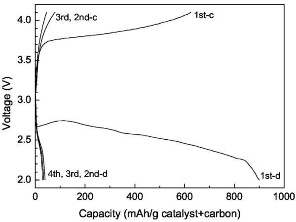
Figure 13 shows the charge/discharge curves of a preliminary Li/O2 cell based on the 1 M LiTFSI/P13TFSI/PVDF-HFP polymer gel electrolyte membrane. The capacity of the first discharge is about 900 mAh/g (carbon plus catalyst) and the voltage plateau is around 2.5 V. The capacity of the first charge is 625 mAh/g (carbon plus catalyst). These data are encouraging considering that the engineering aspects of the air electrode and the cell assembly have not been optimized. The fact that electrocatalytic oxygen reduction can take place with the ionic liquid as the electrolyte solvent is also scientifically interesting, suggesting possible applications of ionic liquids not only for metal/air batteries but also fuel cells. However, subsequent discharge/charge capacities are rather low. Alternating current impedance tests were carried out after the cell setup and after each discharge. The interface resistance between the air electrode and polymer gel electrolyte membrane (RO2/Elyte) and that between the Li foil and membrane (RLi/Elyte) as determined by the tests are listed in Table II. It was found that RO2/Elyte did not increase dramatically upon cycling, suggesting basic stability of the air electrode for repeated discharging/ charging in the solid-state cell based on the polymer gel electrolyte membrane. However, RLi/Elyte increased dramatically upon cycling, preventing further discharge. A thick lithium oxide layer on the Li anode was observed after discharge/charge cycling. A similar thick lithium oxide layer was also observed when the Li/O2 cell was kept in the open circuit state but the air electrode side was exposed to O2 flow for one week. Oxygen crossover from the cathode to the anode to react with Li is likely the cause for the dramatic increase of RLi/Elyte. It appears necessary to suppress the oxygen crossover to achieve rechargeability and improve cycle life of the Li/O2 cells.
Figure 13.
Discharge/charge curves of a preliminary Li/O2 cell based on the 1 M LiTFSI/P13TFSI/PVDF-HFP polymer gel electrolyte membrane; current density is 0.05 mA/cm2 air electrode.
Table II.
Interfacial resistances upon cycling of the Li/O2 cell.
| RO2/Elyte | RLi/Elyte | |
|---|---|---|
| Initial setup state | - | 180 |
| After 1st discharge | 69 | 1958 |
| After 2nd discharge | 80.6 | 2936 |
| After 3rd discharge | 125 | 2571 |
| After 4th discharge | 127 | 2560 |
Conclusion
Ionic liquid 1-methyl-3-propylpyrrolidinium bis(trifluoromethanesulfonyl)imide (P13TFSI) is a promising solvent for the electrolyte of Li batteries because it possesses a wide electrochemical stability window and relatively low viscosity and is stable with respect to Li reduction reaction. Dimensionally stable, elastic, flexible, non-volatile polymer gel electrolyte with desirable properties can be readily synthesized by mixing LiTFSI/P13TFSI solution with PVDF-HFP copolymer.
NMR indicates that the smallest Li ion shows the lowest self-diffusion coefficient among Li+, , and TFSI−, which is ascribed to high degree of association of Li+-xTFSI− ion. Ethylene carbonate (EC) has been demonstrated as a good Li ion transport enhancer in the LiTFSI/P13TFSI/PVDF-HFP polymer gel electrolyte. Adding a small amount of EC can improve ionic conductivity, net Li ion transport number, and Li ion transport kinetic dramatically. The EC with low volatility only slightly decreases the thermal and anodic stability of polymer gel electrolytes which are still stable enough for practical application. Polymer gel electrolytes LiTFSI/P13TFSI/PVDF-HFP with added small amounts of EC are promising for the application of Li batteries including an open system like Li/air cell, as well as conventional Li ion batteries. Preliminary discharge/charge results of Li/O2 cell are encouraging for further improvement. The problem of oxygen crossover in the cell needs to be solved or alleviated for further progress.
Acknowledgments
The portion of this work carried out at Rutgers University was supported by the U.S. Office of Naval Research, grant N00014-04-1-0399. The research performed at Hunter College was supported in part by a grant from the Office of Naval Research and a National Institutes of Health RCMI Infrastructure grant (no. RR-03037).
References
- 1.Tarascon J-M, Armand M. Nature (London) 2001;414:359. doi: 10.1038/35104644. [DOI] [PubMed] [Google Scholar]
- 2.Hamlen RP, Atwater TB. In: Handbook of Batteries. 3rd ed. Linden D, Reddy TB, editors. McGraw-Hill; New York: 2002. p. 38.1. [Google Scholar]
- 3.Abraham KM, Jiang Z. J. Electrochem. Soc. 1996;143:1. [Google Scholar]
- 4.Read J. J. Electrochem. Soc. 2002;149:A1190. [Google Scholar]
- 5.Bonhote P, Dias AP, Papageorgiou N, Kalyanasundaram K, Gratzel M. Inorg. Chem. 1996;35:1168. doi: 10.1021/ic951325x. [DOI] [PubMed] [Google Scholar]
- 6.McEwen AB, Ngo HL, LeCompte K, Goldman JL. J. Electrochem. Soc. 1999;146:1687. [Google Scholar]
- 7.Caja J, Dunstan TDJ, Ryan DM, Katovic V. In: Molten Salts XII. Trulove PC, De Long HC, Stafford GR, Deki S, editors. PV 99-41. The Electrochemical Society Proceedings Series; Pennington, NJ: 2000. p. 150. [Google Scholar]
- 8.Webber A, Blomgrem GE. In: Advances in Lithium-Ion Batteries. Schalkwijk W. A. v., Scrosati B., editors. Kluwer Academic/Plenum; New York: 2002. p. 185. [Google Scholar]
- 9.Sakaebe H, Matsumoto H. Electrochem. Commun. 2003;5:594. [Google Scholar]
- 10.Shin JH, Henderson WA, Passerini S. Electrochem. Commun. 2003;5:1016. [Google Scholar]
- 11.Xu W, Angell CA. Science. 2003;302:422. doi: 10.1126/science.1090287. [DOI] [PubMed] [Google Scholar]
- 12.Noda A, Susan MABH, Kudo K, Mitsushima S, Hayamizu K, Watanabe M. J. Phys. Chem. B. 2003;107:4024. [Google Scholar]
- 13.Doyle M, Choi SK, Proulx G. J. Electrochem. Soc. 2000;147:34. [Google Scholar]
- 14.Rogers RD, Seddon KR. Ionic Liquids: Industrial Applications for Green Chemistry. American Chemical Society; Washington, D.C.: 2002. p. 1. [Google Scholar]
- 15.Matsumoto H, Yanagida M, Tanimoto K, Kojima T, Tamiya Y, Miyazaki Y. In: Molten Salts XII. Trulove PC, De Long HC, Stafford GR, Deki S, editors. PV 99-41. The Electrochemical Society Proceedings Series; Pennington, NJ: 2000. p. 186. [Google Scholar]
- 16.Seki S, Kobayashi Y, Miyashiro H, Ohno Y, Mita Y, Usami A, Terada N, Watanabe M. Electrochem. Solid-State Lett. 2005;8:A577. [Google Scholar]
- 17.MacFarlane DR, Meakin P, Sun J, Amini N, Forsyth M. J. Phys. Chem. B. 1999;103:4164. [Google Scholar]
- 18.Howlett PC, MacFarlane DR, Hollenkamp AF. Electrochem. Solid-State Lett. 2004;7:A97. [Google Scholar]
- 19.Hayashi K, Nemoto Y, Akuto K, Sakurai Y. J. Power Sources. 2005;146:689. [Google Scholar]
- 20.Sutto TE, Trulove PC, De Long HC. In: Molten Salts XIII. Trulove PC, De Long HC, Stafford GR, Deki S, editors. PV 2002-19. The Electrochemical Society Proceedings Series; Pennington, NJ: 2002. p. 134. [Google Scholar]
- 21.Shin J-H, Henderson WA, Passerini S. Electrochem. Solid-State Lett. 2005;8:A125. [Google Scholar]
- 22.Shin J-H, Henderson WA, Passerini S. J. Electrochem. Soc. 2005;152:A978. [Google Scholar]
- 23.Noda A, Hayamizu K, Watanabe M. J. Phys. Chem. B. 2001;105:4603. [Google Scholar]
- 24.Hayamizu K, Aihara Y, Nakagawa H, Nukuda T, Price WS. J. Phys. Chem. B. 2004;108:19527. [Google Scholar]
- 25.Bryne N, Howlett PC, MacFarlane DR, Forsyth M. Adv. Mater. (Weinheim, Ger.) 2005;17:2497. [Google Scholar]
- 26.Tiyapiboonchaiya C, Pringle JM, Sun J, Byrne N, Howlett PC, MacFarlane DR, Forsyth M. Nat. Mater. 2004;204:29. doi: 10.1038/nmat1044. [DOI] [PubMed] [Google Scholar]
- 27.Katayama Y, Yukumoto M, Miura T. Electrochem. Solid-State Lett. 2003;6:A96. [Google Scholar]
- 28.Sato T, Maruo T, Marukane S, Takagi K. J. Power Sources. 2004;138:253. [Google Scholar]
- 29.Fuller J, Breda AC, Carlin RT. J. Electrochem. Soc. 1997;144:L67. [Google Scholar]
- 30.Fuller J, Breda AC, Carlin RT. J. Electroanal. Chem. 1998;459:29. [Google Scholar]
- 31.Watanabe M, Mizumura T. Solid State Ionics. 1996;86–88:353. [Google Scholar]
- 32.Noda A, Watanabe M. Electrochim. Acta. 2000;45:1265. [Google Scholar]
- 33.Song JY, Wang YY, Wan CC. J. Power Sources. 1999;77:183. [Google Scholar]
- 34.Tarascon JM, Gozdz AS, Schmutz CN, Shokoohi F, Warren PC. J. Power Sources. 1996;86–88:49. [Google Scholar]
- 35.Xu JJ, Ye H, Huang J. Electrochem. Commun. 2005;7:1309. [Google Scholar]
- 36.James J, Davis H, Gordon CM, Hilgers C, Wasserscheid P. In: Ionic Liquid in Synthesis. Wasserscheid P, Welton T, editors. Wiley-VCH; New York: 2003. p. 7. [Google Scholar]
- 37.Stejskal EO, Tanner JE. J. Chem. Phys. 1965;42:288. [Google Scholar]
- 38.Stejskal EO. J. Chem. Phys. 1965;43:3597. [Google Scholar]
- 39.Matsumoto H, Yanagida M, Tanimoto K, Nomura M, Kitagawa Y, Miyazaki Y. Chem. Lett. 2000;29:922. [Google Scholar]
- 40.Gray FM. Polymer Electrolytes. The Royal Society of Chemistry; Cambridge: 1997. p. 1. [Google Scholar]
- 41.Nicotera I, Oliviero C, Henderson WA, Appetecchi GB, Passerini S. J. Phys. Chem. B. 2005;109:22814. doi: 10.1021/jp053799f. [DOI] [PubMed] [Google Scholar]
- 42.Xu K. Chem. Rev. (Washington, D.C.) 2004;104:4303. doi: 10.1021/cr030203g. [DOI] [PubMed] [Google Scholar]
- 43.Fukushima E, Roeder SBW. Experimental Pulse NMR: A Nuts and Bolts Approach. Addison-Wesley; Reading, MA: 1981. p. 164. [Google Scholar]


