Abstract
In situ forming drug delivery systems provide a means by which a controlled release depot can be physically inserted into a target site without the use of surgery. The release rate of drugs from these systems is often related to the rate of implant formation. Currently, only a limited number of techniques are available to monitor phase inversion, and none of these methods can be used to visualize the process directly and noninvasively. In this study, diagnostic ultrasound was used to visualize and quantify the process of implant formation in a phase inversion based system both in vitro and in vivo. Concurrently, sodium fluorescein was used as a mock drug to evaluate the drug release profiles and correlate drug release and implant formation processes. Implants comprised of three different molecular weight poly(lactic-co-glycolic acid) (PLGA) polymers dissolved in 1-methyl-2-pyrrolidinone (NMP) were studied in vitro and a 29 kDa PLGA solution was evaluated in vivo. The implants were encapsulated in a 1% agarose tissue phantom for five days, or injected into a rat subcutaneously and evaluated for 48 hrs. Quantitative measurements of the gray-scale value (corresponding to the rate of implant formation), swelling, and precipitation were evaluated using image analysis techniques, showing that polymer molecular weight has a considerable effect on the swelling and formation of the in situ drug delivery depots. A linear correlation was also seen between the in vivo release and depot formation (R2=0.93). This study demonstrates, for the first time, that ultrasound can be used to noninvasively and nondestructively monitor and evaluate the phase inversion process of in situ forming drug delivery implants, and that the formation process can be directly related to the initial phase of drug release dependent on this formation.
Keywords: in situ, ultrasound, scaffold, image analysis, in vitro test, drug delivery
1. Introduction
Treatment of solid tumors using systemic chemotherapy alone is often unsuccessful. Obstacles such as heterogeneous tumor vasculature and elevated intratumoral pressure, among many others, limit drug bioavailability at the site of action and reduce therapeutic efficacy. Approaches that increase the local drug concentration at the target site through physical or chemical targeting can potentially overcome these pitfalls. For example, surgical placement of drug eluting polymer implants directly into the tumor can minimize systemic drug exposure while simultaneously increasing the level of drug within the tumor to several times above the minimum therapeutic dose [1–5]. However, physical placement of pre-formed drug eluting polymer systems is often invasive and can limit their clinical utility [1]. Phase sensitive in situ forming polymer systems that form solid drug depots upon injection into an aqueous environment offer a compelling alternative to solid prefabricated implants because they can be placed through noninvasive image guided procedures [1, 5, 6].
A phase sensitive in situ forming implant system typically consists of a biodegradable hydrophobic polymer dissolved in a water miscible, biocompatible organic solvent [7–9]. An example of this system is poly(lactic-co-glycolic acid) (PLGA) dissolved in either 1-methyl-2-pyrrolidinone (NMP) or triacetin. A similar system has been used successfully in commercial applications for the delivery of leuprolide, which is used for the treatment of prostate cancer. In the Eligard® system, the drug is suspended in the polymer solution and upon injection forms a solid drug depot that can release leuprolide for up to six months [10–13]. Once the polymer solution comes in contact with the aqueous environment, the polymer precipitates forming a solid implant via a process known as phase inversion [14–19]. Phase inversion of the implants begins immediately after the implant comes in contact with the aqueous phase, resulting in the formation of an outer shell surrounding a gel-like interior that consists of the polymer, solvent, drug and, to a significantly lower extent, water. During phase inversion the organic solvent diffuses out of the polymer solution into the surrounding environment, while water diffuses into the implant causing further precipitation of the interior gel-like region [15–18]. These implants have a distinct release pattern consisting of a period of burst release followed by a period of diffusion facilitated release. As the matrix begins to degrade, the release is enhanced until the entire cache of drug has finally been depleted [20]. It has been shown that the drug release from PLGA is directly related to the rate of phase inversion, and that the burst release may be directly correlated to the rate of phase inversion and the resultant morphology of the polymer phase. Some of the variables that are expected to affect the rate of phase inversion are the molecular weight of the polymer, polymer concentration, the hydrophilicity of the solvent, and the non-solvent composition [16, 17, 21].
Currently only a handful of techniques are available to evaluate the phase inversion process of in situ forming systems. Dark ground optics have been used in previous investigations of the phase inversion phenomenon [15–18]. The dark ground optical system uses a filtered laser beam to image the interference fringes that are caused by water diffusion into the polymer solution. Reflected light is used in conjunction with the laser in order to image the polymer that has undergone phase inversion. The dark ground optical system has been invaluable in evaluating the underlying mechanisms involved in the phase inversion process, but is limited to thin films and can only be used for a short time scale relative to the life of the implant [15–18]. Another common technique for imaging in situ forming implants is scanning electron microscopy [3, 16, 17, 20, 22, 23]. One shortcoming of this technique is that the implants are destroyed in the process, since sample preparation most often involves freezing and sectioning of the implants. Electron paramagnetic resonance (EPR) has recently been investigated as a means to nondestructively and noninvasively monitor the phase inversion process of the implant, but this technique cannot be used to generate images of the implants and requires the use of small molecular weight paramagnetic spin probes [24, 25]. EPR is currently the only technique that can be used to noninvasively study the phase inversion process in vivo. Furthermore, none of the aforementioned techniques provide a means for noninvasive quantitative analysis while simultaneously generating images of the implants.
We have recently developed a novel means of evaluating the phase-inversion process of in situ forming implants through the use of diagnostic ultrasound and subsequent quantitative image analysis. Ultrasound refers to sound waves with a frequency above 20 kHz [26]. In diagnostic ultrasound, a piezoelectric transducer converts electrical energy into mechanical pressure waves that propagate through a material. The backscatter is a result of the impedance differences existing within a material, such that the reflectance can be described as:
The resultant image is therefore an acoustic map of the mechanical interactions of the pressure waves with the object, as described by the difference in impedance with the surrounding environment [27]. Since the in situ implants transition from liquid solution to solid implant, the change in phase alters the impedance of the implant, allowing visualization of the phase inversion process with ultrasound. The use of imaging to monitor changes within a system is well established and has several advantages over existing techniques [5, 25, 27, 28]. Most importantly the method is nondestructive, thus the formation data, drug release data, solvent release data, and swelling data can all be obtained from the same implant. In addition, because the technique is noninvasive, the same implants can be imaged over the time scale of seconds to months, providing unprecedented longitudinal information regarding immediate formation as well as implant degradation. These processes can be measured regardless of the geometry of the implant, making it applicable to a wide variety of systems and experiments. Finally, the evaluation can be performed in vitro as well as in vivo to provide an accurate representation of the implant properties in an undisturbed physiological environment. The goal of the current study was to demonstrate the utility of ultrasound as a noninvasive, non-destructive tool to evaluate the phase inversion processes of these implants in vitro and in vivo and to relate this information to the drug release profiles in these environments.
2. Materials and Methods
2.1 Materials
All materials were used as received with no further purification. Poly(DL-lactide-co-glycolide) (PLGA 50:50: 2A, MW 15,000 Da, inherent viscosity 0.16dL/g; 3A, MW 29,000 Da, inherent viscosity 0.28 dL/g; 4A, MW 64,000 Da, inherent viscosity 0.46dL/g) was obtained from Lakeshore Biomaterials, Birmingham, AL. N-methyl pyrrolidinone (NMP) and sodium fluorescein (MW 376.28) were obtained from Sigma Aldrich, St. Louis, MO. Agarose was obtained from Fisher Scientific, Waltham, MA. 1,1′-dioactadecyl-3,3,3′,3′-tetramethyl-indocarbocyanine perchlorate (DiI) was obtained from Invitrogen, Eugene, OR.
2.2 Preparation of Polymer Solutions
Solutions of 40 wt % PLGA in NMP were prepared with 2A, 3A, and 4A polymers. Polymer was added to NMP in scintillation vials and allowed to mix overnight in an incubated shaker at 37°C until the polymer had completely dissolved. Polymer solutions were stored at 4°C for up to three days before use. For release studies, sodium fluorescein was used as a mock drug and polymer solutions were made as described previously using a 60:39:1 mass ratio of solvent:polymer:drug [29].
2.3 Polymer Encapsulation in Agarose
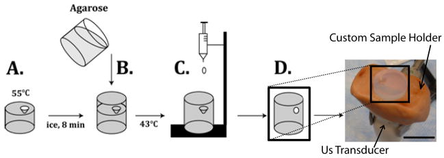
A 1% agarose solution was used to encapsulate the implant in a tissue phantom for the duration of the study. Liquid agarose was stored in a warm water bath. Warm agarose (9ml) was added to the mold and placed on a bed of ice. Before the phase transition of the agarose was complete, an additional 6ml of boiling agarose was added to the mold, and allowed to cool to below the glass transition temperature of the PLGA (43.5°C), at which time a drop of the polymer solution (25 mg) was added and the agarose was allowed to solidify (Figure 1).
Figure 1.
Agarose was added to a mold and allowed to cool for 8 min (A). An additional layer of agarose was then added and allowed to cool below the glass transition temperature of the PLGA (B). Implant was formed by dropping PLGA/NMP solution into the void created by the mold (C) resulting in the final phantom (D) placed in the custom fabricated holder. Scale bar represents 1.75 cm.
The phantom was placed in a 150ml bath of 37°C diH2O, and images were recorded after 40 min, 1 hr, 2 hrs, and then every other hour for the first 10 hrs, and once daily for the next 5 days. Four implants were examined for each molecular weight of PLGA.
2.4 In Vitro Ultrasound Imaging
The implants were imaged using a Toshiba Aplio SSA-770A diagnostic ultrasound. A 12MHz PLT-120 transducer was used with the following parameters: a dynamic range of 55, a mechanical index of 1.1, a gain of 80, and a depth of 3 cm. The transducer was fixed using a clamp, and the phantom was imaged from the bottom, and held in a constant position by a custom fabricated holder. The phantom was rotated in the holder until the center of the implant was found, and then the agarose was marked so that the same plane would be imaged throughout the study. Images were acquired after 40 min, 1 hr, 2 hrs, and then every other hour for the first 10 hrs, and once daily for the next 5 days and stored as TIFF images.
2.5 In Vivo Ultrasound Imaging
All animal experiments were carried out under general gas anesthesia strictly following a protocol approved by the Case Western Reserve University Institutional Animal Care and Use Committee. Five six week old male BDIX rats (average body weight 300g, Charles River Laboratories Inc., Wilmington, MA) were used. 1% isoflurane was used with an oxygen flow rate of 1 L/min (EZ150 Isoflurane Vaporizer, EZ Anesthesia™). Due to the consistent behavior and injectability of the 3A implants during the first 48hrs, these implants were chosen for use in the in vivo studies to determine if a correlation existed with the burst period of drug release and the phase inversion of the polymer implants [14]. 50μl of fluorescein loaded polymer solution was injected subcutaneously at five locations on the dorsal side of the rat using a 21-gauge hypodermic needle. The implants were imaged using a Toshiba Aplio SSA-770A diagnostic ultrasound with a 12MHz PLT-120 transducer using the following parameters: a dynamic range of 55, a mechanical index of 1.1, a gain of 80, and a depth of 3 cm. Images were taken at 1 hr, 4 hrs, 8 hrs, 24 hrs, and 48 hrs.
2.6 Image Analysis
Ultrasound images are the visualization of the backscattered signal that arises due to the difference in mechanical impedance between different materials and phases. The backscattered signal is displayed as a gray-scale array with values ranging from 0–256, with 0 indicating a negligible difference in impedance from the surrounding media, in this case 1% agarose. The liquid polymer solution has low mechanical impedance and generates a negligible backscattered signal, while the phase inverted polymer causes significant reflection of the pressure waves, resulting in an image. The development of an ultrasound signal over time was interpreted as an increase in impedance due to the precipitation of the polymer
The Gray-scale value (GV) was analyzed by measuring the mean GV of the implants over time, so that an index of the matrix impedance could be evaluated and used as a means to evaluate the change in the mechanical properties of the matrix over time. The mean GV was analyzed by first finding all pixels with values greater than zero in the implant. Then the average of the non-zero values was determined. Implants initially form a thin shell that thickens over time as the polymer phase inverts, therefore, the growth of the precipitation front can be determined by measuring the change in shell thickness over time. First, for in vitro analysis the region of interest (ROI) was isolated by using a parametric intensity based segmentation method of mixed Gaussians [30]. Gaussian intersections were used to threshold the image foreground from the background. The image was then converted from gray scale to binary, and then the implant interior was filled to create a total area image (Figure 2). For in vivo analysis, the implants were manually segmented (five images for each implant), and a threshold value was selected using the method of mixed Gaussians after the ROI was isolated in order to remove low intensity noise. The ROI was used to create the total area image. The measurements from the five images were averaged together for each implant.
Figure 2.

Representative isolated gray scale image of the 3A implant (A). The implant after a threshold has been applied (B). The total area image generated from the threshold image (C). The scale bar represents 0.25cm.
The ratio of the number of pixels that comprised the unfilled region of the threshold image to the total number of pixels in the total area image was used to determine the percent formation. The initial 10 hrs of the study were used to quantitatively describe the shell growth in vitro. For the in vitro images, plateau (Pr) and time delay terms (τ) of an exponential equation were fit using the sum of least squares with MATLAB, and these terms were used as a means by which the formation rate of the different polymers could be compared.
Finally, implant swelling was determined in vitro from the total area images. Since the total area images were binary, the number of implant pixels could be determined by summation of the pixels. Then sums were normalized by dividing the number of implant pixels in the total area image at a given time point by the number of implant pixels in the total area image of the first time point. All image analysis was performed using MATLAB.
2.7 Image Validation
Agarose phantoms were constructed as previously described, but the polymer solution was prepared by adding a small amount (less than 0.1 mg) of a hydrophobic DiI dye during solution preparation in order to enhance contrast of the implants. The implants were then imaged with ultrasound at 2 hrs, 6 hrs, and 24 hrs. After ultrasound imaging, the implants were frozen, sliced, and photographed for comparison with the ultrasound images.
2.8 Drug Release
In vitro release studies were carried out by first placing agarose entrapped 3A implants (n=3) in 150 ml of 37°C diH2O, and incubating at 37°C on a rotating shaker table. At 1, 4, 8, 24, and 48 hrs, the implants were removed from the agarose phantom and degraded in 2M NaOH. The agarose was returned to the bath side and both the bath side and implant were left overnight. The total fluorescein mass was determined by measuring the fluorescence from the bath side solution and the dissolved implant solution, then concentration was determined using a standard curve. The cumulative mass release was normalized by calculating the total mass of fluorescein in the implants.
In vivo release studies were performed by determination of residual fluorescein in a subcutaneous 3A implant at 1, 4, 8, 24, and 48 hrs (n=5). After US image acquisition at these time points, the animal was euthanized and the implants were dissected out and degraded overnight in 2M NaOH solution; fluorescein concentration was determined using a standard curve. Cumulative mass release was normalized by the theoretical mass of fluorescein in the implants. For both in vivo and in vitro studies the fluorescence was measured using a Tecan 200 series plate reader at an excitation wavelength of 485nm and an emission wavelength of 525nm.
2.9 Statistical Analysis
ANOVA was used to determine statistical significance (P<0.05, N=4). A Tukey multiple comparison test was used to identify significantly different groups. Error is reported as the standard error of the mean (SEM).
3. Results
3.1 Image Validation
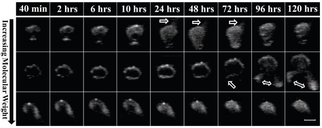
Representative gray-scale images of PLGA implants are shown in Figure 3. Some implants exhibited “leakage” of the polymer into the surrounding agarose (indicated by the arrows) which was caused by an increase in hydrostatic pressure as a result of implant swelling. The constrained nature of implants encapsulated in agarose allows a limited degree of swelling to occur before the implants reach a critical threshold that forces any remaining liquid polymer solution through the agarose along the plane with the lowest resistance. Leakage occurred within 24 hrs of the 2A implants, and could be seen as early as 72 hrs after implantation in the 3A implants. Leakage did not occur in the 4A implants (Figure 3).
Figure 3.
Representative isolated gray scale images of the implants over time, the polymer molecular weight increases from top to bottom with 2A on the top row, 3A in the middle, and 4A on the bottom row. The scale bar represents 0.25cm. The arrow indicates where leakage has occurred.
Validation of the US images was performed by entrapping DiI loaded implants in agarose so that an US image could be obtained and compared with the actual implant (Figure 4).
Figure 4.
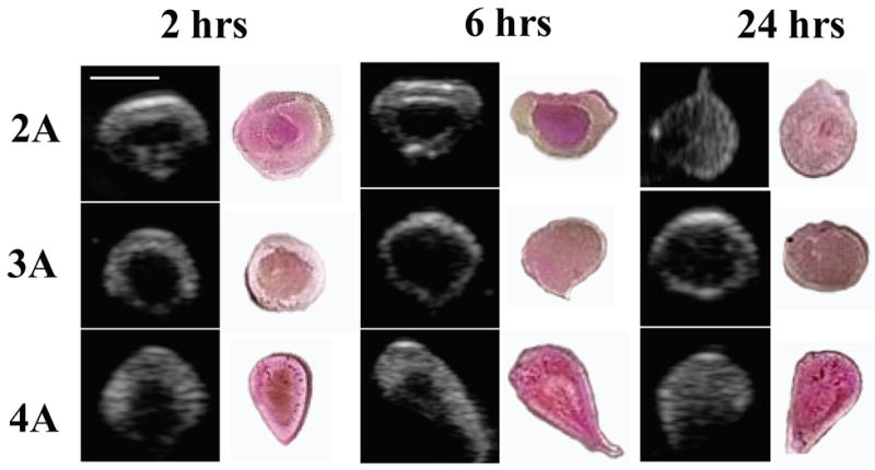
Representative gray-scale images of the implants over time next to photos of the actual implant, the polymer molecular weight increases from top to bottom. Scale bar represents 0.25cm.
Due to the hydrophobicity of the DiI dye, the darker pink regions were assumed to be hydrophobic-rich regions that contained polymer and solvent, while the lighter regions were hydrophilic domains [14]. All US images corresponded to the sectioned implants.
3.2 Gray-Scale Analysis
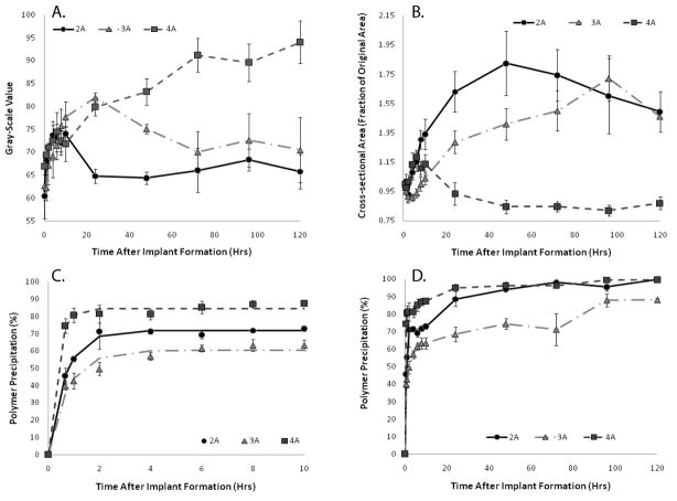
2A polymers had a maximum mean GV of 74±3 after 10 hrs, but the mean GV decreased to 65±3 after 24 hrs in the agarose phantom. 3A polymers had a maximum GV of 82±2 after 24 hrs, but decreased to a value of 70±9 by day 3. The 2A and 3A polymers were no longer statistically different (p<0.05) after 72 hrs in the agarose phantom, with the mean GV of both polymer types decreasing. The 4A polymers attained the highest mean GV, 94±8 after 3 days, and appeared to plateau after 72 hrs in the agarose phantom, becoming statistically different from the other polymer types after 48 hrs of encapsulation in the agarose phantom (Figure 5A). The change in the gray-scale intensity of the implants over time can be seen in Figure 3.
Figure 5.
Changes in mean GV of the three molecular weight polymers over time (A). Quantitative swelling data of the three molecular weight polymers (B). Quantitative formation data for three molecular weight polymer implants over the first 10hrs of formation (C). Formation data for the full 120 hr study (D). 2A(^), 3A( ), 4A(
 )
)
3.3 Implant Swelling
The 2A polymer exhibited the greatest swelling within the first 24 hrs, increasing in size more than 60%. Implant cross-sectional area reached a maximum of 80% total increase after 48 hrs, and then began to shrink gradually. The 3A polymer showed an initial decrease in size, shrinking 10% after one hour in the agarose phantom, but then steadily increased in size, reaching a 20% increase within 24 hrs and an 80% increase after 96 hrs. Finally, the 4A polymer showed an initial increase in cross-sectional area to approximately 120% of the initial area within the first 5 hrs. After 5 hrs, the cross-sectional area decreased slightly and remained constant for the duration of the experiment (Figure 5B).
3.4 Implant Formation
The plateau value (Pr) from the parametric analysis was used to describe the percent of the polymer that had undergone phase inversion sufficient for creation of an echogenic signal. All three polymers had statistically different Pr values, with the 4A polymer having the highest Pr value followed by the 2A and then the 3A (Table 1). Both the 2A and the 4A polymers reached precipitation values above 95% 48 hrs after implantation in the agarose phantom, while the 3A polymer approached 90% precipitation after 96 hrs. A sharp increase in polymer precipitation occurred after the leakage of the polymer solution from the depot with the 2A and 3A polymers (Figure 5C–D).
Table 1.
Summary of parametric analysis for the first ten hours of formation List of and values from.
plateau value indicating extent of precipitation
time delay
statistically significant difference (p<0.05) within parameter group
The time delay value (τ) was used to aid in describing the effect of time on polymer formation. The 4A polymer had a statistically different τ from both the 2A and 3A polymers, but the 2A and 3A polymers were not statistically different from each other (Table 1).
3.5 In Vivo Formation
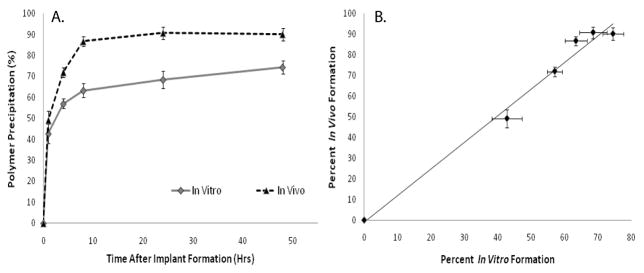
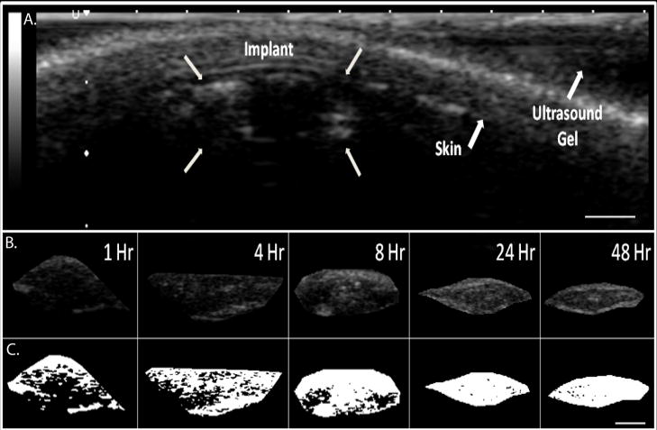
3A polymer implants were evaluated in vivo for 48 hrs following injection. Precipitated polymer occupied 86±5% of the total cross-sectional area within 8 hrs and reached a maximum value of 90±6.4% after 24 hrs at which time the implant formation had reached a plateau (Figure 7A). Representative gray-scale images obtained from the in vivo analysis are shown in Figure 6. A linear correlation was found between the in vivo and in vitro formation (R2=.98, Figure 7B).
Figure 7.
Quantitative formation data for the 3A polymer implants in vivo and in vitro (A), linear correlation of the in vivo and in vitro formation data (R2=0.9845, B). In Vivo (▴), In Vitro ( )
)
Figure 6.
A. Representative ultrasound image of subcutaneous implant after 1 hr; arrows indicate location of the implant, skin, and ultrasound gel. B. isolated gray scale images of the in vivo subcutaneous implants over time, C. threshold image of the same implant (shown in B.). Scale bar represents 0.25cm.
3.6 Drug Release
The in vitro implants released 46±4.8% of the total drug mass within the first 8 hrs, and a total of 50±1.8% mass released after 48 hrs (Figure 8). In comparison, in vivo implants released 61±8.6% of the drug after 8 hrs and released 82±6.3% of the drug after 48 hrs (Figure 8B). Release from the in vivo and in vitro implants was not statistically different until 8hrs (P=0.047) at which time the release was statistically different for the duration of the study. A strong linear correlation was seen between the percent polymer precipitation and the percent mass release in vivo and in vitro (R2=.93 and R2=.9486, Figure 9).
Figure 8.
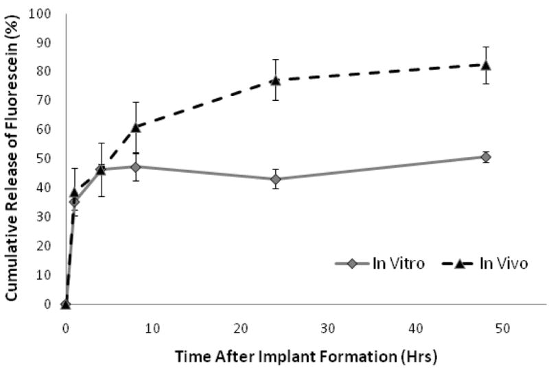
Cumulative release of fluorescein from 3A polymer implants encapsulated in and agarose and subcutaneously injected implants. In Vivo (▴), In Vitro ( )
)
Figure 9.
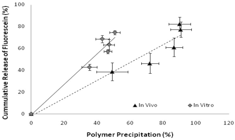
Correlation of in vivo and in vitro release data with in vivo and in vitro formation (in vitro R2=0.9486 and in vivo R2=0.93). In Vivo (▴), In Vitro ( )
)
4. Discussion
The use of diagnostic ultrasound to study the phase inversion process of in situ forming implants is a novel means to evaluate the process in a noninvasive, nondestructive manner. The primary advantage of this technique is the real time visualization of the implant formation process. Through the use of quantitative image analysis techniques, long term information regarding formation and swelling behavior for the same implant over time can be obtained. Additionally, by monitoring the phase inversion process, factors that may affect drug delivery such as polymer leakage or fibrous encapsulation may be monitored. The ability to evaluate these phenomena provides a means by which the effectiveness of the implants can be ascertained clinically. In the current study, the utility of monitoring implant formation using ultrasound was demonstrated by analyzing the effect of polymer MW on the formation and swelling of in situ forming PLGA-NMP.
The behavior of implants embedded in agarose was monitored in a tissue phantom. Change in the implants over time can be seen in Figure 3. Polymer leakage can be seen after 24 hrs with the 2A polymer and after 72 hrs with the 3A polymer. While polymer leaking was not anticipated, it is suspected to have occurred due to the increase in hydrodynamic pressure that corresponded with the increase in implant swelling. Ultimately, because the implant was constrained by the agarose, residual polymer burst from the implant along the weakest plane of the agarose phantom. The driving force for this phenomenon is hypothesized to be the osmolarity of the implants. Due to the small MW, the 2A implants would have the highest number of moles at a given mass resulting in the highest osmotic force; additionally the affinity of the polymer for the solvent would add to the osmotic affect further enhancing the osmotic drive. As a consequence, these implants would swell the fastest and be the first of the polymers to show signs of leakage. The delayed leakage seen in the 3A implants could be a result of the degradation byproducts increasing the osmolarity and subsequently increasing the water content of the implants which would result in increased phase inversion. Consequently, the sudden change in surface area may adversely affect drug delivery resulting in a large burst release of drug, which would not be detectable using any other technique to evaluate phase inversion. The leakage phenomenon could prove to be potentially problematic in environments that would enhance polymer degradation (such as the acidic environment of a tumor). The enhanced degradation may increase the implant osmolarity ultimately resulting in enhanced swelling and leakage of the implants leading to undesirable burst of drug. Therefore, in agreement with prior work it is clear that the environment in which the implant is formed plays a crucial role during implant formation and subsequent drug release process [31]. The propensity for the lower molecular weight polymers to swell highlights the importance of polymer selection when optimizing for specific delivery applications in vivo.
The average GV was intended to be used as an index to determine the degree of depot formation, with lower mean GVs corresponding to a more fluid matrix and large mean GVs correlating to fully-formed solid depots. Using this measurement, it was observed that the 4A PLGA depots attained the highest gray scale value, indicating nearly complete solvent diffusion and implant precipitation. In contrast, the mean GV of 2A implants reached a plateau after 4 hrs, suggesting a lack of further change in matrix stiffness. The 2A implants also showed a reduction in gray-scale value after 24 hrs, which corresponded to leakage of the implant. This limited the mean GV index as a tool for determining the degree of formation. A similar decrease in mean GV was noted in the 3A depot after leakage was seen on day 3.
Implant swelling was measured as a change in cross-sectional area over time. The 2A depot increased in size drastically in 24 hrs, and a high degree of swelling was not seen with the 3A until after 72 hrs. The decrease in cross-sectional area seen in the 3A and 4A depots was most likely caused by diffusion of solvent out of the depot occurring at a faster rate than water influx and resulting in a loss in total implant volume.
Many variables can be manipulated to alter the precipitation rate of the in situ forming polymer system. Often, the desired kinetics can simply be achieved with the appropriate selection of an excipient and solvent [18]. It has been reported that implant formulations comprised of high molecular weight polymers in solvents with high water miscibility will undergo a rapid phase inversion resulting in a characteristic honeycomb like structure of diffusion pores for drug and water to travel through [17, 32]. When NMP is used as the solvent, the critical concentration of water required to induce phase inversion decreases as the molecular weight of the polymer increases, due to the change in affinity of the solvent for the polymer. Therefore, it was anticipated that the rate of polymer precipitation would occur fastest with the 4A PLGA followed by 3A, and 2A PLGA [18, 29]. A parametric analysis of the process showed that while the 4A implants did in fact form the fastest, gelation rates of the 2A and 3A implants were not statistically different. Our data indicated that the 2A polymer had undergone a greater degree of precipitation than the 3A PLGA. This disparity is attributed to the difference in initial osmotic drive. However, although the change in impedance was sufficient to induce backscatter in the 2A implants, it is clear that this data alone cannot be used as a standalone tool to dictate when the implants have completely solidified. Instead, the combination of GV and precipitation must be used to determine the state of the implant.
In vitro analysis of polymer precipitation and drug release showed a high degree of correlation within the first 48 hrs. This relationship is most likely related to the release of drug during the precipitation of the polymer. Interestingly, the correlation begins to wane as the mechanism of delivery transitions from burst release to a form of diffusion mediated release. Differences were seen between the in vitro and in vivo release rates after 8 hrs, which may be attributed to the difference in surface area and more importantly convective removal of solvent and drug, which consequently enhances the polymer precipitation.
Because of the novelty of the ultrasound characterization technique, little data is currently available for direct comparison of our results. In the most applicable study, Kempe et al. noninvasively evaluated the phase inversion dynamics of an in situ forming implant similar to the 3A polymer using EPR [24]. While our results were similar in vivo, they differ with respect to the precipitation rate of the polymer in vitro. The deviations may be explained by the vastly different nature of the two techniques. In particular, the rate of solvent and water exchange is limited in the agarose phantom which may lead to delayed implant formation. Additionally, it is possible that the spin probe required for EPR analysis may affect the phase inversion dynamics of the implants [33]. One benefit of our technique is that phase inversion can be monitored without the need of a probe, which is required for EPR. However, EPR is able to measure the solvent exchange process which currently cannot be examined with ultrasound imaging.
5. Conclusion
This study has demonstrated, for the first time, that it is possible to noninvasively and nondestructively image the phase inversion process using a diagnostic ultrasound. The phase inversion data can then be directly related to the rate of drug release, providing a new means for the study of in situ forming implants in in vivo applications. While ultrasound has several advantages over traditional methods, it is limited by the resolution of the images. This makes ultrasound ideal for analyzing the macro-scale behavior of the implants, but traditional techniques, such as SEM analysis, can provide complimentary, higher resolution information. Additionally, while the study of implants in a constrained environment provided insight into their behavior, additional studies need to be performed in a nonconstrained system, so that the relationship between the GV and the solidification of the implant can be better understood. Overall, this novel technique is a powerful means by which in situ forming drug delivery depots can be monitored and studied noninvasively throughout the lifespan of the implant. Potential applications of this technique include high throughput screening for new implant development and simplified in vitro/in vivo correlation of implant properties. The US technique is not limited to phase sensitive in situ forming polymer systems and may be applied to other in situ forming systems, such as ones undergoing phase transition due to temperature or pH. Furthermore, the noninvasive analysis may be utilized in fields outside of drug delivery to monitor the behavior of polymer implants in tissue engineering and related applications.
Supplementary Material
An in vitro ultrasound video showing the instantaneous formation of a 4A implant injected into diH2O.
An in vivo ultrasound video showing the instantaneous formation of a 4A implant injected into a BDIX rat tumor model.
Time lapse image compilation showing the change in formation of a 2A implant injected into water at 0 min, 5 min, 10 min, 15 min, 20 min, 40 min, 1 hr, 3 hrs, and 5 hrs.
Acknowledgments
This work was supported by NIH grant R01CA118399 to AAE. LS was also supported in part by the NIH grant 1T32EB007509-01 to Case Western Reserve University Interdisciplinary Biomedical Imaging Training Program.
Footnotes
Publisher's Disclaimer: This is a PDF file of an unedited manuscript that has been accepted for publication. As a service to our customers we are providing this early version of the manuscript. The manuscript will undergo copyediting, typesetting, and review of the resulting proof before it is published in its final citable form. Please note that during the production process errors may be discovered which could affect the content, and all legal disclaimers that apply to the journal pertain.
Contributor Information
Luis Solorio, Email: luis.solorio@case.edu, Department of Biomedical Engineering, Case Western Reserve University, 10900 Euclid Ave, Cleveland, OH 44106, phone: 216-844-0077, fax: 216-844-5922.
Brett M. Babin, Email: bbabin@student.umass.edu, Department of Chemical Engineering, University of Massachusetts Amherst, 686 North Pleasant St, Amherst, MA 01003, phone: 413-545-2507, fax: 413-545-1647
Ravi B. Patel, Email: ravi.patel@case.edu, Department of Biomedical Engineering, Case Western Reserve University, 10900 Euclid Ave, Cleveland, OH 44106, phone: 216-983-3011, fax: 216-844-5922
Justyna Mach, Email: justyna.mach@gmail.com, Department of Biomedical Engineering, Case Western Reserve University, 10900 Euclid Ave, Cleveland, OH 44106, phone: 216-844-0077, fax: 216-844-5922.
Nami Azar, Email: nami.azar@uhhospitals.org, Department of Radiology, Case Center for Imaging Research, Case Western Reserve University, 11100 Euclid Ave, Cleveland, OH 44106, phone: 216-844-8417, fax: 216-844-5922.
Agata A. Exner, Email: agata.exner@case.edu, Department of Radiology, Case Center for Imaging Research, Case Western Reserve University, 11100 Euclid Ave, Cleveland, OH 44106, phone: 216-844-3544, fax: 216-844-5922
References
- 1.Exner AA, Saidel GM. Drug-eluting polymer implants in cancer therapy. Expert Opin Drug Deliv. 2008;5(7):775–788. doi: 10.1517/17425247.5.7.775. [DOI] [PubMed] [Google Scholar]
- 2.Jain RK. Delivery of molecular and cellular medicine to solid tumors. Adv Drug Deliv Rev. 2001;46(1–3):149–168. doi: 10.1016/s0169-409x(00)00131-9. [DOI] [PubMed] [Google Scholar]
- 3.Kranz H, Bodmeier R. Structure formation and characterization of injectable drug loaded biodegradable devices: in situ implants versus in situ microparticles. Eur J Pharm Sci. 2008;34(2–3):164–172. doi: 10.1016/j.ejps.2008.03.004. [DOI] [PubMed] [Google Scholar]
- 4.Saltzman WM, Fung LK. Polymeric implants for cancer chemotherapy. Adv Drug Deliv Rev. 1997;26(2–3):209–230. doi: 10.1016/s0169-409x(97)00036-7. [DOI] [PubMed] [Google Scholar]
- 5.Szymanski-Exner A, Stowe NT, Salem K, Lazebnik R, Haaga JR, Wilson DL, Gao J. Noninvasive monitoring of local drug release using X-ray computed tomography: optimization and in vitro/in vivo validation. J Pharm Sci. 2003;92(2):289–296. doi: 10.1002/jps.10295. [DOI] [PubMed] [Google Scholar]
- 6.Qian F, Saidel GM, Sutton DM, Exner A, Gao J. Combined modeling and experimental approach for the development of dual-release polymer millirods. J Control Release. 2002;83(3):427–435. doi: 10.1016/s0168-3659(02)00217-1. [DOI] [PubMed] [Google Scholar]
- 7.Dunn RL, Tipton AJ. Polymeric compositions useful as controlled release implants. 5, 702, 716. US Patent. 1997 Dec 30;
- 8.Dunn RL, English JP, Cowsar DR, Vanderbilt DP. Biodegradable in situ forming implants and methods of producing the same. 4, 938, 763. US Patent. 1990 July 3;
- 9.Royals MA, Fujita SM, Yewey GL, Rodriguez J, Schultheiss PC, Dunn RL. Biocompatibility of a biodegradable in situ forming implant system in rhesus monkeys. J Biomed Mater Res. 1999;45(3):231–239. doi: 10.1002/(sici)1097-4636(19990605)45:3<231::aid-jbm11>3.0.co;2-h. [DOI] [PubMed] [Google Scholar]
- 10.Berges R, Bello U. Effect of a new leuprorelin formulation on testosterone levels in patients with advanced prostate cancer. Curr Med Res Opin. 2006;22(4):649–655. doi: 10.1185/030079906X96425. [DOI] [PubMed] [Google Scholar]
- 11.Sartor O. Eligard: leuprolide acetate in a novel sustained-release delivery system. Urology. 2003;61(2 Suppl 1):25–31. doi: 10.1016/s0090-4295(02)02396-8. [DOI] [PubMed] [Google Scholar]
- 12.Schulman C, Alcaraz A, Berges R, Montorsi F, Teillac P, Tombal B. Expert opinion on 6-monthly luteinizing hormone-releasing hormone agonist treatment with the single-sphere depot system for prostate cancer. BJU Int. 2007;100(Suppl 1):1–5. doi: 10.1111/j.1464-410X.2007.06967.x. [DOI] [PubMed] [Google Scholar]
- 13.Astaneh R, Nafissi-Varcheh N, Erfan M. Zinc-leuprolide complex: preparation, physicochemical characterization and release behaviour from in situ forming implant. J Pept Sci. 2007;13(10):649–654. doi: 10.1002/psc.894. [DOI] [PubMed] [Google Scholar]
- 14.Hatefi A, Amsden B. Biodegradable injectable in situ forming drug delivery systems. J Control Release. 2002;80(1–3):9–28. doi: 10.1016/s0168-3659(02)00008-1. [DOI] [PubMed] [Google Scholar]
- 15.Mchugh AJ, Miller DC. The Dynamics of Diffusion and Gel Growth during Nonsolvent-Induced Phase Inversion of Polyethersulfone. Journal of Membrane Science. 1995;105(1–2):121–136. [Google Scholar]
- 16.Graham PD, Brodbeck KJ, McHugh AJ. Phase inversion dynamics of PLGA solutions related to drug delivery. J Control Release. 1999;58(2):233–245. doi: 10.1016/s0168-3659(98)00158-8. [DOI] [PubMed] [Google Scholar]
- 17.Brodbeck KJ, DesNoyer JR, McHugh AJ. Phase inversion dynamics of PLGA solutions related to drug delivery. Part II. The role of solution thermodynamics and bath-side mass transfer. J Control Release. 1999;62(3):333–344. doi: 10.1016/s0168-3659(99)00159-5. [DOI] [PubMed] [Google Scholar]
- 18.McHugh AJ. The role of polymer membrane formation in sustained release drug delivery systems. J Control Release. 2005;109(1–3):211–221. doi: 10.1016/j.jconrel.2005.09.038. [DOI] [PubMed] [Google Scholar]
- 19.Packhaeuser CB, Schnieders J, Oster CG, Kissel T. In situ forming parenteral drug delivery systems: an overview. Eur J Pharm Biopharm. 2004;58(2):445–455. doi: 10.1016/j.ejpb.2004.03.003. [DOI] [PubMed] [Google Scholar]
- 20.Astaneh R, Erfan M, Moghimi H, Mobedi H. Changes in morphology of in situ forming PLGA implant prepared by different polymer molecular weight and its effect on release behavior. J Pharm Sci. 2009;98(1):135–145. doi: 10.1002/jps.21415. [DOI] [PubMed] [Google Scholar]
- 21.Luan X, Bodmeier R. Influence of the poly(lactide-co-glycolide) type on the leuprolide release from in situ forming microparticle systems. J Control Release. 2006;110(2):266–272. doi: 10.1016/j.jconrel.2005.10.005. [DOI] [PubMed] [Google Scholar]
- 22.Eliaz RE, Kost J. Characterization of a polymeric PLGA-injectable implant delivery system for the controlled release of proteins. J Biomed Mater Res. 2000;50(3):388–396. doi: 10.1002/(sici)1097-4636(20000605)50:3<388::aid-jbm13>3.0.co;2-f. [DOI] [PubMed] [Google Scholar]
- 23.Rafienia M, Emami SH, Mirzadeh H, Mobedi H, Karbasi S. Influence of poly (lactide-co-glycolide) type and gamma irradiation on the betamethasone acetate release from the in situ forming systems. Curr Drug Deliv. 2009;6(2):184–191. doi: 10.2174/156720109787846243. [DOI] [PubMed] [Google Scholar]
- 24.Kempe S, Metz H, Mader K. Do in situ forming PLG/NMP implants behave similar in vitro and in vivo? A non-invasive and quantitative EPR investigation on the mechanisms of the implant formation process. J Control Release. 2008;130(3):220–225. doi: 10.1016/j.jconrel.2008.06.006. [DOI] [PubMed] [Google Scholar]
- 25.Kempe S, Metz H, Pereira PG, Mader K. Non-invasive in vivo evaluation of in situ forming PLGA implants by benchtop magnetic resonance imaging (BT-MRI) and EPR spectroscopy. Eur J Pharm Biopharm. 2009 doi: 10.1016/j.ejpb.2009.06.008. [DOI] [PubMed] [Google Scholar]
- 26.Ng KY, Matsunaga TO. Ultrasound mediated drug delivery. In: Wang B, Siahaan TJ, Soltero R, editors. Drug Delivery: Principles and Applications. John Wiley & Sons, Inc; Hoboken: 2005. pp. 245–278. [Google Scholar]
- 27.Bushberg JT, Seibert JA, Leidholdt EM, Boone JM. Ultrasound. In: Passano WM, editor. The Essential Physics of Medical Imaging. Williams & Wilkins; Baltimore: 1994. pp. 367–416. [Google Scholar]
- 28.Strasser JF, Fung LK, Eller S, Grossman SA, Saltzman WM. Distribution of 1,3-bis(2-chloroethyl)-1-nitrosourea and tracers in the rabbit brain after interstitial delivery by biodegradable polymer implants. J Pharmacol Exp Ther. 1995;275(3):1647–1655. [PubMed] [Google Scholar]
- 29.Patel RB, Carlson A, Solorio L, Exner AA. Characterization of formulation parameters affecting low molecular weight drug release from in situ forming drug delivery systems. Journal of Biomaterials Research Part B. 2009 doi: 10.1002/jbm.a.32724. [DOI] [PMC free article] [PubMed] [Google Scholar]
- 30.Sonka M, Hlavac V, Boyle R. Image Processing, Analysis, and Machine Vision. 3. CL Engineering; Portland, State: 2007. [Google Scholar]
- 31.Mulder M. Basic Principles of Membrane Technology. 2. Kluwer Academic Publishers; Dordrecht, State: 1996. [Google Scholar]
- 32.Raman C, McHugh AJ. A model for drug release from fast phase inverting injectable solutions. J Control Release. 2005;102(1):145–157. doi: 10.1016/j.jconrel.2004.09.022. [DOI] [PubMed] [Google Scholar]
- 33.Tang Y, Singh J. Controlled delivery of aspirin: effect of aspirin on polymer degradation and in vitro release from PLGA based phase sensitive systems. Int J Pharm. 2008;357(1–2):119–125. doi: 10.1016/j.ijpharm.2008.01.053. [DOI] [PubMed] [Google Scholar]
Associated Data
This section collects any data citations, data availability statements, or supplementary materials included in this article.
Supplementary Materials
An in vitro ultrasound video showing the instantaneous formation of a 4A implant injected into diH2O.
An in vivo ultrasound video showing the instantaneous formation of a 4A implant injected into a BDIX rat tumor model.
Time lapse image compilation showing the change in formation of a 2A implant injected into water at 0 min, 5 min, 10 min, 15 min, 20 min, 40 min, 1 hr, 3 hrs, and 5 hrs.


