Abstract
Chronic tissue response to microelectrode implants stands in the way as a major challenge to development of many neural prosthetic applications. The long term tissue response is mostly due to the movement of interconnects and the resulting mechanical stress between the electrode and the surrounding neural tissue. Remotely activated floating micro-stimulators are one possible method of eliminating the interconnects. As a method of energy transfer to the micro-stimulator, we proposed to use a laser beam at near infrared (NIR) wavelengths. FLAMES of various sizes were fabricated with integrated silicon PIN photodiodes. Sizes varied from 120 (Width) × 300 (Length) × 100 (Height) μm to 200 × 500 × 100μm. Devices were bench tested using 850nm excitation from a Ti:Sapphire laser. To test this method, the voltage field of the FLAMES was experimentally tested in saline solution pulsed with a NIR laser beam. The voltage generated is around 196mV in peak at the cathodic contact as a response to a single pulse. When a train of laser pulses was applied at 100Hz, the peak voltage at the cathodic contact remained around 141mV suggesting the feasibility of this approach for applications with pulse frequencies up to 100Hz.
Keywords: Neural Microstimulation, wireless microstimulators
I. INTRODUCTION
Electrical stimulation is currently used as a treatment method for a number of disorders of the central and peripheral nervous systems. Many of these applications demand very localized activation of the neural tissue at multiple sites to produce functional changes in the neural activity. In order to achieve this high spatial selectivity, microelectrode arrays with multiple shanks that are penetrating into the neural tissue have been developed [1], [2]. One of the major challenges of chronically implanted electrodes with penetrating shanks is the mechanical stress and the resulting chronic tissue response induced by the movement of the electrode and the tethering of interconnects. This tethering problem can be solved by replacing the interconnects with telemetry, both for powering the device and controlling the stimulus parameters.
As a potential way of eliminating interconnects, we are investigating the use of NIR light to transfer energy to the microstimulator. To achieve the level of spatial selectivity needed especially in the central nervous system applications, the device needs to be in the submillimeter range and be able to inject sufficient current for neural stimulation.
In the envisioned paradigm, the micro-stimulator will be implanted into the neural tissue at the targeted site of the CNS. The laser source and control electronics will be implanted at a distant site, e.g. subclavicular area, that is most convenient for transcutaneous charging of batteries and programming of the pulse parameters. A multi-mode optical fiber will be used to transfer the laser pulses near the micro-stimulator to activate it. The tip of the optical fiber will be located just above the micro-stimulator, but outside the dura matter, possibly inserted through a hole into the skull or vertebrae. Therefore, the distance that the laser beam has to travel will only be in the order of a few millimeters through the neural tissue above the microstimulator.
For the laser source, near infrared (NIR) wavelengths will be chosen because the wavelengths ranging approximately from 700 to 900nm have the maximum penetration depth into the neural tissue. In general, light photons propagate inside the tissue by scattering off the molecules until they are absorbed. The optical wavelength and tissue type are the primary factors that determine the scattering and absorption coefficients. The penetration depth is primarily determined by the scattering coefficient in the NIR wavelengths since the scattering coefficient is much larger than the absorption coefficient [3], however still relatively low making the NIR wavelengths ideal for penetration into neural tissue [4]. Another motivation for choosing NIR range is that semiconductor lasers available at NIR wavelengths are not bulky as the lasers that operate at longer wavelengths.
In this study, we fabricated various sizes of floating light activated micro-electrical stimulators (FLAMESs) with integrated, Si PIN photodiodes. The electrode sites were coated with TiN to improve the charge injection capacity. The voltage field generated by the FLAMES was tested experimentally by placing the device in a volume conductor and measuring the voltage field generated. Voltage fields generated by floating microstimulators were simulated before using finite element method [5].
II. METHODS
A. Device Fabrication
Ion implantation was used to create the electrically active areas of the photodiodes. Boron was implanted to produce the p-type areas (the anode) and phosphorus to produce the n-type areas (the cathode), as depicted in Fig. 1. Ion implantation provided an abrupt doping profile in the P-I-N regions of the photodiodes, which increased the depletion width of the photodiode and maximized the device efficiency.
Fig. 1.
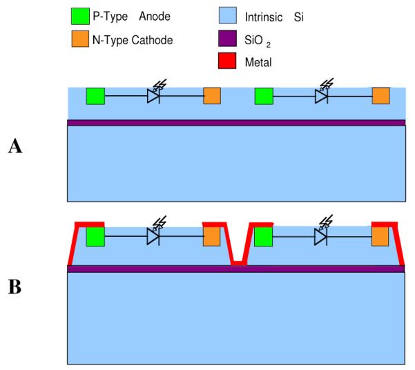
A) Ion implantation is used to fabricate the PIN junctions (photodiodes). B) Individual photodiodes are electrically isolated by etching trenches through the top silicon layer of SOI.
Individual photodiodes had to be electrically isolated. This is a critical step because a leakage path between photodiodes will hinder the voltage summation in cascaded devices. The electrical isolation of individual photodiodes was achieved by implementing the devices on silicon-on-insulator (SOI) wafers. SOI wafers consist of a thin silicon dioxide layer (the buried oxide, purple lines in Figs. 1) that lies between two silicon layers. Following the fabrication of the photodiodes on the top silicon layer, the photodiodes were electrically isolated by etching trenches through the top silicon layer (Fig. 1B). Metal connections were made between anodes and cathodes of adjacent photodiodes, resulting in cascaded (series) diodes.
The last step of the FLAMES fabrication was to release the devices from the wafer. This was done by etching a deep trench, through the entire thickness of the wafer, around the perimeter of the devices. This technique allowed fabrication of devices with custom shapes such as an angled tip that will facilitate the implantation into neural tissue. A scanning electron microscope (SEM) image of a FLAMES with three cascaded photodiodes is shown in Fig. 2. We fabricated devices with sizes varying from 120 (Width) × 300 (Length) × 100 (Depth) μm to 200×500×100μm with various active and contact areas. Final device thickness was made 100μm in the current design. Fig.3 shows pictures of a version of the FLAMES with a shank. The long shank was needed to handle the devices with ease during testing.
Fig. 2.
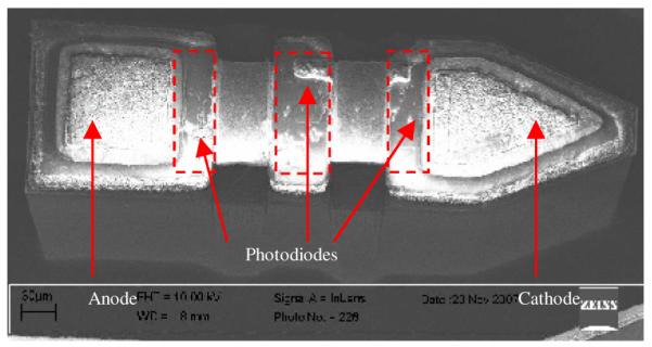
SEM image of a fabricated FLAMES that has three cascaded photodiodes and no shank.
Fig. 3.
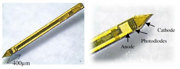
Left: A version of the FLAMES fabricated with a shank (4mm length) for handling the device during testing. Right: The active part of the device for converting NIR light to electrical current.
A parallel resistor (not shown in the figures) was incorporated into some of the photodiodes by implanting a long p+ strip into the p− bulk. The function of this parallel resistance is to discharge the contact interface capacitance during the off cycles. By controlling the concentration of the dopants as well as the dimensions of the implants, we varied the leakage resistors from 50 to 200k. These resistors will shunt about 10% of device current during the on cycles.
B. Volume Conductor Measurements
Volume conductor measurements were conducted in normal saline (0.9%) diluted ten times to simulate the specific resistivity of the CNS white matter (~700 cm [6]). The device was secured at the bottom of a petri dish. A tungsten micro-electrode and a large Ag/AgCl reference was used to record the voltage field generated by the device, in response to a laser beam at 830nm, pulsing at 1, 10, 20, or 100Hz (PW= 0.2ms). The laser source (DLS-500-830FS-100, StockerYale, Canada, 74mW) and acquisition of the signals into the computer were controlled by a custom LabVIEW program (National Instruments, TX). The laser beam size and power were sufficiently large to saturate the photodiodes during each pulse. The voltage field generated inside the solution was recorded with the tungsten electrode placed immediately above the cathode, without making a direct contact.
III. RESULTS
A. On Bench Measurements
Photodiodes were tested using standard electronic test equipment and 850nm excitation from a Ti:Sapphire laser. The devices displayed expected photodiode characteristics and satisfied the predicted performance criteria. Voltage-current characteristics for single and multiple photodiodes in series are shown in Fig. 4. As expected, the turn on voltage for cascaded devices increases linearly. Two important benchmark parameters for photodiodes are small dark currents and high reverse bias breakdown voltages. Dark current measurements showed less than 100nA current at - 4V bias and no evidence of breakdown was observed for a reverse bias voltage of 15V.
Fig. 4.
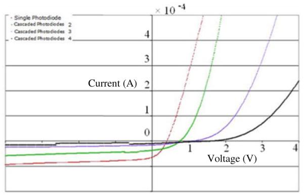
Voltage – Current characteristics of FLAMES. Single, two, three and four series connected devices are shown. The illumination power is 700μW, λ = 850nm. Red: Single photodiode, Green: two cascaded photodiodes, Purple: three cascaded photodiodes, Black: four cascaded photodiodes.
B. Volume Conductor Measurements
Figure 5 shows the voltage field generated in saline immediately above the cathode of the FLAMES. The response of the FLAMES is largely capacitive. It decays slowly as the TiN interface capacitance is charging. The cathode voltage peak is about 196mV. A positive voltage spike is expected at the beginning of the off cycle while the contact capacitance is discharging through the parallel resistor. The absence of this spike suggests that the parallel resistor value may be too large in this case.
Fig. 5.
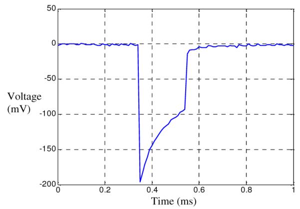
Volume conductor measurements. The waveform recorded above the center of the cathode as a response to a single pulse.
In Fig. 6, a train of laser pulses at 100Hz is applied to the device and the field potentials are recorded immediately above the cathode. The volume conductor voltage peak is about 141mV in steady state after several pulses. The voltage peak remains constant with each successive pulse. Similar pulse waveforms were observed at 10 and 20Hz with voltage peaks of 189, and 186mV respectively.
Fig. 6.
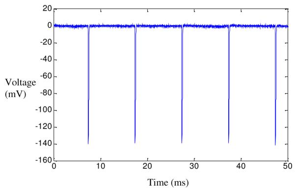
Volume conductor measurements. The waveform recorded above the center of the cathode while applying a train of laser pulses at 100Hz to the device active area.
IV. DISCUSSION
In this study, we tested prototype FLAMES activated by NIR laser. Both the bench and volume conductor results suggest that the FLAMES approach is feasible for neural stimulation. The voltage-current characteristics for the photodiodes were as expected. The differential voltage generated between the two contacts seems sufficiently large to activate nearby nerve cells. The voltage is directly proportional to the specific resistivity of the medium which is assumed to be 700 c m in this study. Haueisen et al. reports resistivity values as high as 450 c m for the gray matter and an average value of 700 c m for the white matter [6].
After applying a train of laser pulses at 100Hz, the peak voltage at the cathodic contact remained around 141mV demonstrating the feasibility of this approach for applications that require frequencies up to 100Hz. Devices that were capable of generating similar voltage fields were tested in the sciatic nerve of an adult rat by our group [7]. Each laser pulse was followed by an EMG response, demonstrating that FLAMES could generate sufficient current for stimulation of peripheral nerves.
A floating, wireless stimulator with micrometer dimensions can be an important step towards realization of many neural prosthetic ideas that require localized activation of neural tissue, especially in the most mobile parts of the nervous system such as the spinal cord. The human spinal cord experiences substantial translational and rotational displacements that make chronic implantation of microwire electrodes nearly impossible. Implantation of sufficient number of FLAMES in the visual cortex for a visual prosthesis may prove to be challenging at the end. In the spinal cord, however, a few channels of stimulation can be sufficient to restore function [8]-[10].
ACKNOWLEDGMENT
This study was funded by the National Institutes of Health/NINDS Grant (R21 NS050757).
REFERENCES
- [1].Perlin GE, Wise KD. A compact for three-dimensional neural microelectrode arrays. IEEE Int. Engr. In Med. and Biol. Conf.; Vancouver, BC. August 2008; pp. 5806–5809. [DOI] [PubMed] [Google Scholar]
- [2].Bhandari1 R, Negi1 S, Rieth L, Normann RA, Solzbacher F. A novel masking method for high aspect ratio penetrating microelectrode arrays. J. Micromech. Microeng. 2009;vol. 19 [Google Scholar]
- [3].Gurnani P. Master Thesis. University of Texas at Arlington; 2003. Near infrared spectroscopic measurement of human and animal brain structures. [Google Scholar]
- [4].Eggert HR, Blazek V. Optical properties of human brain tissue, meninges, and brain tumors in the spectral range of 200 to 900nm. Neurosurgery. 1987;vol. 21(no 4) doi: 10.1227/00006123-198710000-00003. [DOI] [PubMed] [Google Scholar]
- [5].Sahin M, Ur-Rahman SS. Finite element analysis of a floating microstimulator. IEEE Tran. on Neural Systems and Rehab. 2007;vol. 15(no 2):227–234. doi: 10.1109/TNSRE.2007.897027. [DOI] [PMC free article] [PubMed] [Google Scholar]
- [6].Haueisen J, Ramon C, Czapski P, Eiselt M. On the influence of volume currents and extended sources on neuromagnetic fields: a stimulation study. Ann. Biomed. Eng. 1995;vol. 23:728–739. doi: 10.1007/BF02584472. [DOI] [PubMed] [Google Scholar]
- [7].Gray KM, Sahin M. Floating light activated micro-electrical stimulator. 35th Neural Interface Workshop; Bethesda, MD. Sept. 2004. [Google Scholar]
- [8].Saiga R, Renzi C, Mushahwar VK. Intraspinal microstimulation generates functional movements after spinal-cord injury. IEEE Tran. on Neural Systems and Rehab. 2004;Vol. 12:430–440. doi: 10.1109/TNSRE.2004.837754. [DOI] [PubMed] [Google Scholar]
- [9].Mushahwar VK, Gillard DM, Gauthier MJA, Prochazka A. Intraspinal microstimulation generates locomotor-like and feedback-controlled movements. IEEE Tran. On Neural Systems and Rehab. Eng. 2002;vol. 10:68–81. doi: 10.1109/TNSRE.2002.1021588. [DOI] [PubMed] [Google Scholar]
- [10].Tai C, Booth AM, Robinson CJ, de Groat WC, Roppolo JR. Multi-joint movement of the cat hindlimb evoked by microstimulation of the lumbosacral spinal cord. Exp. Neur. 2003;vol. 183:620–627. doi: 10.1016/s0014-4886(03)00210-3. [DOI] [PubMed] [Google Scholar]


