

Abstract
We designed, constructed, and tested a single-beam optical trapping instrument employing twin electro-optic deflectors (EODs) to steer the trap in the specimen plane. Compared to traditional instruments based on acousto-optic deflectors (AODs), EOD-based traps offer a significant improvement in light throughput and a reduction in deflection-angle (pointing) errors. These attributes impart improved force and position resolution, making EOD-based traps a promising alternative for high precision nanomechanical measurements of biomaterials.
Optical traps are formed by focusing an intense laser to a diffraction-limited spot using a microscope objective of high numerical aperture (NA), and allow the precise manipulation of micron-scale polarizable objects, such as polystyrene or silica beads [1]. The force response of an optical trap is Hookean for small displacements and scales linearly with laser power. Once trap stiffness is appropriately calibrated, a constant force can be exerted on a moving particle by implementing a force clamp, which typically uses feedback to maintain a fixed separation between the particle and trap center [2-6]. By applying forces to biomolecules, the energy landscapes for mechanochemical reactions can be tilted in controlled ways, revealing mechanistic details of biological processes involving motion [6-8].
When a trapping instrument is operated in force-clamp mode, the position of the beam must be rapidly updated with high precision. This task is commonly performed using an acousto-optic deflector (AOD), a crystal subjected to ultrasound that generates an optical diffraction grating with a period set by the acoustic wavelength and a diffraction efficiency that scales with amplitude [2, 4, 6]. Using an AOD, it is possible to control trap position and stiffness by modulating the acoustic drive frequency and amplitude, respectively. The first-order diffracted light is deflected through an angle, θ, that depends on frequency, f, through θ = λf/v, where λ is the optical wavelength and v is the acoustic wave velocity. Maximum deflections around ±1° are possible at λ = 1064 nm. AODs suffer from disadvantages that limit their usefulness in high-resolution applications. Transmittance varies over the working range of drive frequencies, which can cause trap stiffness to change as it is moved. More importantly, AODs exhibit ‘wiggles’: systematic angular deviations from a linear response to the acoustic drive frequency. These small nonlinearities lead to tracking errors in position, resulting in uncertainties for the applied force and measured position.
To improve transmission and pointing characteristics of the beam-steering optics, we constructed an instrument that incorporates twin electro-optic deflectors (EODs; Conoptics 4CryLTA, 302RM; 200 kHz bandwidth) to deflect the beam along orthogonal axes. An EOD is based on a gradient in refractive index across a crystal subjected to an external electrostatic field. Light is deflected through θ = cLV/w2, where L and w are the crystal length and diameter, V is the applied voltage, and the proportionality constant, c, depends on material properties. For a device with L = 11 cm, w = 2 mm, and V = 375 V, maximal deflections around ±0.1° are possible. In contrast to AODs, which deflect a fraction of the incoming light, EODs, deflect the entire beam, leading to increased throughput and higher trap stiffness.
In our design, we formed a single-beam trap using a continuous wave, near-infrared laser (5 W; 1064 nm) (Fig. 1). Because it is not possible to modulate EOD transmittance, beam intensity was adjusted using halfwave plate (HWP) and polarizing beam-splitting cube (PBS) pairs. One such pair included a motorized rotary HWP (MHWP), allowing computer control of trap stiffness. A single HWP was placed immediately before EOD1 to align polarization to the input axis of the crystal.
Fig. 1.
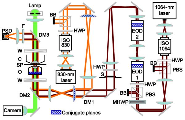
(Color online) Schematic layout for the EOD-based optical trap. Dichroic mirror (DM) DM1 combines trapping (dark red) and detection (light orange) beams. DM2 directs both beams through a Wollaston prism (W) into a high-NA (1.40) microscope objective (O); an optical trap is formed in the specimen plane (SP). A series of lens pairs placed in both laser paths image the objective back focal plane onto the steering lenses and EODs (conjugate planes are indicated by blue hatching). An NA-matched condenser lens (C) collects forward-scattered laser light. DM3 reflects the trapping and detection beams while passing brightfield illumination light from an arc lamp (solid green). A short-pass filter (F) blocks the trapping laser, and a duolateral position-sensitive detector (PSD) collects the detection light. S = shutter, BB = beam block, PBS = polarizing beam splitter, ISO = optical isolator, HWP = halfwave plate, MHWP = motorized halfwave plate.
For angular deviations from the optimal polarization, a “shadow” beam was observed exiting the EODs, with polarization different from that of the primary beam and deflected to a lesser extent. With optimal alignment however, the power in this parasitic beam could be reduced to ~1-2% of that of the fully-deflected beam. To minimize the contribution of the shadow beam, we placed all HWP-PBS pairs in front of both EODs. We verified that the shadow beam did not significantly perturb the trapping potential by measuring trap stiffness over the range of deflections. Trap stiffnesses measured by three standard methods (the mean-squared displacement for a trapped bead, the corner frequency of its power spectrum, and the drag force at constant fluid velocity) agreed to within 20% at a fixed trap position [1]. Measurements at different trap deflection positions by any single method agreed within 10%; for all positions, power spectra were Lorentzian and distributions of displacements were Gaussian.
EODs were situated such that their axes of deflection were positioned in planes optically conjugate to the back focal plane (BFP) of the objective [1], which produces pure rotations of the beam at the objective entrance pupil. Rotations in this plane, in turn, generate pure translations of the focal spot in the specimen plane. Despite the length of the EOD, a narrowly-defined deflection plane could be identified empirically by measuring deflections over a range of voltages and tracing the beams back to a single vertex within the crystal body.
To characterize our instrument, we measured the transmission and tracking error of the two EODs placed in series. We then compared the performance of this device to one where trap steering was performed by two AODs in series and aligned for maximal throughput.
The transmittance of both EODs (measured by a meter placed after EOD2) was 81% and varied by <0.5% over the deflection range, which corresponded to a trap displacement of ±0.76 μm in the specimen plane (Fig. 2). For two AODs (IntraAction DTD-274HA6, ATD-274HA1-6, CVE), the transmittance in the first-order diffracted beam was 55% at maximal amplitude. Transmission varied by ~5% for displacements of ±0.75 μm; for larger displacements of ±2.5 μm, >20% variation in transmittance was observed (Fig. 2).
Fig. 2.

Transmittance as a function of trap position for orthogonal deflectors. The EOD-based optical trap (left) displayed ~81% transmittance with <0.5% variation for displacements of ±0.76 μm in the specimen plane (corresponding to the full working range), whereas the AOD-based optical trap (right) displayed ~55% transmittance with >20% variation for displacements of ±2.5 μm (±2.5 MHz around center frequencies of 21.8 MHz in the x-dimension; 30 MHz in the y-dimension).
We compared the accuracy of AOD- and EOD-based deflection by moving a particle along a programmed, linear trajectory. To test deflections at different angles, a 0.44 μm diameter bead was moved in an eight-armed ‘star’ pattern as position was determined by monitoring the scattering of a detection laser (830 nm wavelength), as described previously [3, 5]. For EOD-based deflection, measured displacements corresponded quite well with the target trajectories (Fig. 3, left). For deflections along the positive y-axis, the std. dev. in position on the x-axis was 0.5 nm. For AOD-based deflection, significant and reproducible deviations from target trajectories were observed (Fig. 3, right). These quasi-periodic wiggles arise from unwanted back-reflections from absorbers glued to the crystal inside the AOD, resulting in interference between forward and counter-propagating acoustic traveling waves. The positions and amplitudes of wiggles can change with the amplitude and frequency of the drive signal, as well as with the age of the device, making it difficult to remove these by any simple calibration process; systematic pointing errors have been observed for all AOD crystals used in our laboratory. For deflections along the positive y-axis, the std. dev. in position on the x-axis was 2.0 nm.
Fig. 3.
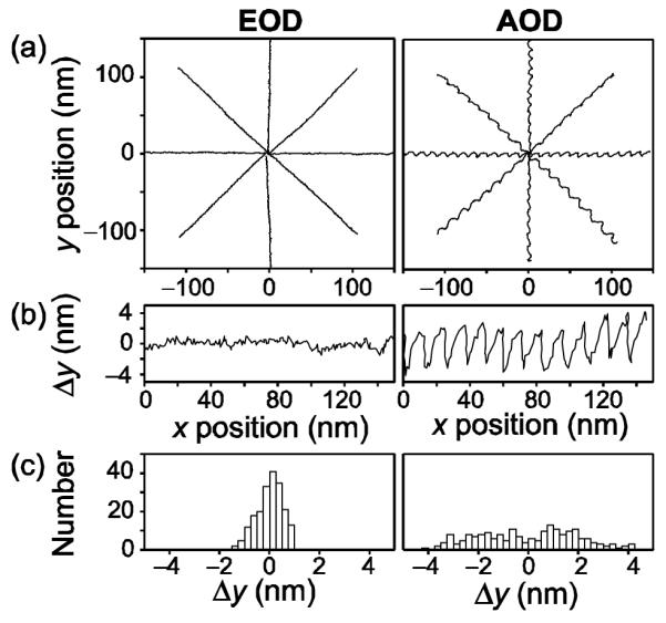
Linearity of EOD and AOD response. (a) A particle trapped ~500 nm above the coverslip surface was moved in an eight-armed star pattern by EOD- (left) or AOD-driven (right) deflections of the trapping beam. Data were sampled at 50 kHz and Bessel filtered at 25 kHz; 1000 samples were averaged at each of 200 positions per arm. The x and y trap stiffnesses (κ) were determined by averaging values estimated by two methods: (1) the mean-squared displacement and (2) the corner frequency of the Lorentzian power spectrum [1]. For the EOD-based device, κx = 0.16 pN nm−1 and κy = 0.20 pN nm−1; for the AOD-based device, κx = 0.27 pN nm−1 and κy = 0.16 pN nm−1. (b) EOD-driven beads accurately followed the targeted trajectory, as seen in an expanded view (left). AOD-driven particles (right) displayed characteristic wiggles (see text). (c) Histograms of the displacement data in panel (b).
To demonstrate the resolution attained by the EOD-based optical trap, we performed single-molecule motility assays using recombinant kinesin protein, as previously described [9]. Individual molecular steps taken by bead-bound kinesin motors, measuring 8.2 nm, could be clearly resolved (Fig 4, black trace), as a constant (hindering) load of −4.9 pN was maintained using EOD-based feedback to control trap position (red line).
Fig. 4.

(Color online) Experimental record showing the displacement of a single kinesin molecule bound to a bead (black) and the corresponding trap position (red) vs. time under force-clamped conditions [6], showing steps of 8.2 nm (dashed grey). A recombinant derivative of D. melanogaster kinesin (DmK612) was used in this assay [9], with [ATP] =100 μM, trap stiffness = 0.07 pN nm−1, and hindering force = −4.9 pN. Inset: cartoon showing the experimental geometry (not to scale), where a single kinesin motor, bound to a bead held in the optical trap, steps along a microtubule attached to the coverslip.
In summary, there are clear advantages to the use of EODs for steering optical traps. EODs offer comparatively greater throughput (~50% more), reduced variation in transmittance with deflection (ten-fold less), and increased linearity in deflection (a four-fold improvement). These features facilitate more precise control over trap stiffness and position. Furthermore, in conjunction with nanoscale distance standards, the improved deflection accuracy may simplify the process of instrument calibration [10]. Excepting applications requiring large-scale deflections, future high-resolution biomechanical measurements stand to benefit from this technology.
Acknowledgments
This work is supported by grant R01-GM51453 from the NIGMS; MTV was supported by a Career Award at the Scientific Interface from the Burroughs Wellcome Fund and NRG and ANF by NSF Predoctoral Fellowships.
Footnotes
OCIS codes: 230.0230, 180.0180, 140.7010, 160.2100.
References
- 1.Neuman KC, Block SM. Optical trapping. Rev. Sci. Instrum. 2004;75:2787–2809. doi: 10.1063/1.1785844. [DOI] [PMC free article] [PubMed] [Google Scholar]
- 2.Simmons RM, Finer JT, Chu S, Spudich JA. Quantitative measurements of force and displacement using an optical trap. Biophys. J. 1996;70:1813–1822. doi: 10.1016/S0006-3495(96)79746-1. [DOI] [PMC free article] [PubMed] [Google Scholar]
- 3.Visscher K, Block S. Versatile optical traps with feedback control. Meth. Enzymol. 1998;298:460–489. doi: 10.1016/s0076-6879(98)98040-5. [DOI] [PubMed] [Google Scholar]
- 4.Visscher K, Schnitzer MJ, Block SM. Single kinesin molecules studied with a molecular force clamp. Nature. 1999;400:184–189. doi: 10.1038/22146. [DOI] [PubMed] [Google Scholar]
- 5.Lang MJ, Asbury CL, Shaevitz JW, Block SM. An automated two-dimensional optical force clamp for single molecule studies. Biophys. J. 2002;83:491–501. doi: 10.1016/S0006-3495(02)75185-0. [DOI] [PMC free article] [PubMed] [Google Scholar]
- 6.Block SM, Asbury CL, Shaevitz JW, Lang MJ. Probing the kinesin reaction cycle with a 2d optical force clamp. Proc. Natl. Acad. Sci. U. S. A. 2003;100:2351–2356. doi: 10.1073/pnas.0436709100. [DOI] [PMC free article] [PubMed] [Google Scholar]
- 7.Veigel C, Molloy JE, Schmitz S, Kendrick-Jones J. Load-dependent kinetics of force production by smooth muscle myosin measured with optical tweezers. Nat. Cell Biol. 2003;5:980–986. doi: 10.1038/ncb1060. [DOI] [PubMed] [Google Scholar]
- 8.Woodside MT, Anthony Peter C., Behnke-Parks WM, Larizadeh K, Hershlag D, Block SM. Direct measurement of the full, sequence-dependent folding landscape of a nucleic acid. Science. 2006;314:1001–1004. doi: 10.1126/science.1133601. [DOI] [PMC free article] [PubMed] [Google Scholar]
- 9.Asbury CL, Fehr AN, Block SM. Kinesin moves by an asymmetric hand-over-hand mechanism. Science. 2003;302:2130–2134. doi: 10.1126/science.1092985. [DOI] [PMC free article] [PubMed] [Google Scholar]
- 10.Rickgauer JP, Fuller DN, Smith DE. DNA as a metrology standard for length and force measurements with optical tweezers. Biophys. J. 2006;91:4253–4257. doi: 10.1529/biophysj.106.089524. [DOI] [PMC free article] [PubMed] [Google Scholar]