Abstract
A 700-mm bore superconducting magnet was built and operated in our laboratory to demonstrate the feasibility of newly developed MgB2 superconductor wire for fabricating MRI magnets. The magnet, an assembly of 10 coils each wound with a reacted and s-glass insulated wire ~1-km long, was immersed in solid nitrogen rather than in a bath of liquid cryogen. This MgB2 magnet was designed to operate in the temperature range 10–15 K, maintained by a cryocooler. A combination of this “wide” temperature range and immersion of the winding in solid nitrogen enables this magnet to operate under conditions not possible with a low temperature superconductor (LTS) counterpart. Tested individually at 13 K, each coil could carry current up to 100 A. When assembled into the magnet, some coils, however, became resistive, causing the magnet to prematurely quench at currents ranging from 79 A to 88 A, at which point the magnet generated a center field of 0.54 T. Despite the presence of a large volume (50 liters) of solid nitrogen in the cold body, cooldown from 77 K to 10 K went smoothly.
Keywords: High-temperature superconductors, magnetic resonance imaging (MRI), MgB2, solid cryogen, superconducting magnets
I. Introduction
SINCE the discovery of superconductivity in MgB2 at temperature of 39 K in year 2001, conductor development has advanced to the stage where MgB2 superconducting wire in kilometer-length is commercially available [1]. A variety of applications have been proposed in making use of the new conductor [2]. In this paper, we report our progress in the construction and test of an MgB2 superconducting magnet. This program aims to demonstrate the feasibility and practicality of low-cost MRI magnet system. As the performance/price ratio of MgB2 becomes competitive to LTS, a wide operating temperature range of MgB2, much wider than that possible with LTS, should make MgB2 the conductor of choice for magnets now dominated by LTS. Instead of operation in the liquid helium temperature range, we are developing a cryogenic system that combines solid nitrogen and cryocooler to maintain the working temperature of an MgB2 magnet. Such a magnet will not depend on helium supply and the presence of solid nitrogen in the cold body enables the magnet (in persistent mode operation) to keep its operating field intact even during a short period of electric power disruption.
II. MgB2 Conductor
The MgB2 wire used in the construction of our magnet was developed by Hyper Tech Research [3]. It is designated as an “18+1 Nb/Cu/Monel” multifilament wire. Fig. 1 shows a photograph of the cross section of the wire. The wire is manufactured with the so-called continuous tube filling and forming (CTFF) process. During this process, MgB2 powder are mixed and wrapped inside niobium strip to form a tube. The tube is then inserted inside a seamless copper tube and drawn to form a monofilament strand. For the 18+1 multifilament wire, 18 monofilament strands and one center copper filament are restacked into seamless Monel tube and then drawn into the final size. The wire is insulated with s-glass sleeve and wound on stainless steel spool of about half meter in diameter. Reaction is done through heat treatment in 700°C for 20 to 40 minutes. Twelve spools, each with ~1-km long MgB2, were delivered to MIT, from which ten spools were used to build our magnet.
Fig. 1.
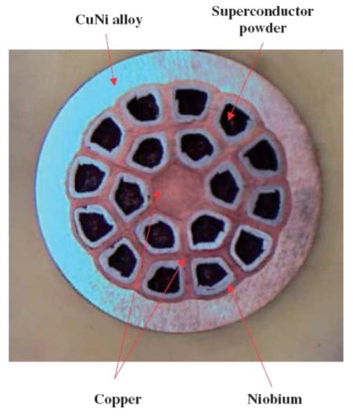
Photograph of the cross section of 0.84-mm diameter 18+1 multifilament MgB2 wire, with key components identified [1].
MgB2 filament is very brittle, and bending of small diameter will degrade its current-carrying capacities. A large diameter MRI magnet is a logical starting point for application of reactivated wire. The strain tolerance of the conductor was reported to be 0.48%. For a winding diameter of 770 mm and a wire diameter of 0.84 mm, the bending strain is well below the permissible strain of 0.48%. Fig. 2 shows the critical current Ic as a function of magnetic field for the multifilament MgB2 wire. The criterion for Ic is Vc = 1 μV across 1 cm. The exponential index n defined as
| (1) |
is shown in Fig. 3. It is worth pointing out that in a magnet normally made of wire with a total length in the order of 104 m, the current it can carry is much less than the Ic specified with the above criterion. In a typical MRI magnet running in persistent current mode, the total resistance is less than 10−10 Ω. Using (1), we estimate the current in the magnet to see if the wire can meet our goal. At the upper limit of the system’s working temperature, 15 K, Ic = 200 A and n = 30, with a total conductor length of 104 m, the magnet can carry a current of 117 A to meet the criterion of 10−10 Ω, which would allow us to run the magnet in a persistent mode. In driven mode, the total magnet resistance can be larger but the Joule heating will still set a limit on its operating current. For the same Ic, n, and the total wire length as above and for a Joule heating limit of 100 mW, the operating current should not exceed 156 A. In the design, the maximum current in the magnet is set at 100 A with a center field of 0.61 T and a peak field in the magnet of 1.2 T.
Fig. 2.
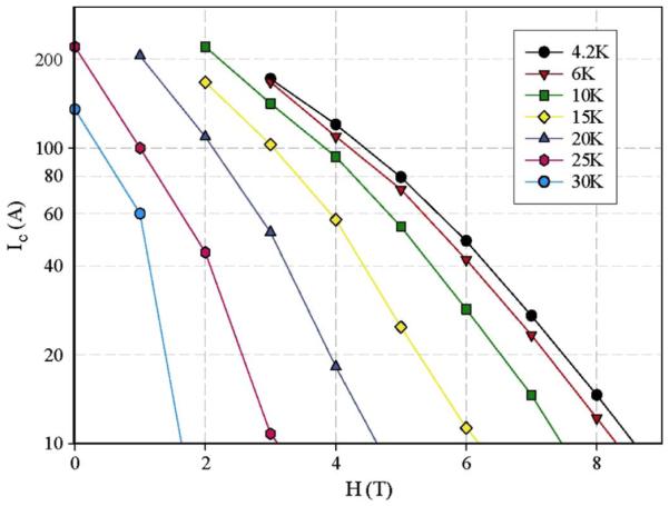
Critical current Ic vs. magnetic field plots at selected temperatures for multifilament MgB2 wire [1].
Fig. 3.
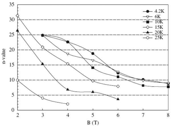
n value versus magnetic field plots for multifilament MgB2 conductors [1].
III. Construction of Coils
The magnet consists of 10 coils, each 770 mm in diameter and 25.4 mm long. On average, 415 turns were wound in each coil. The 10 coils were stacked together and fixed with tie rods. The connections between wires were soldered with 50-50 Sn-Pb solder: the joints are not superconducting at the working temperature between 10 and 15 K. The typical joint resistance is below 1 μΩ. Superconducting joints will replace these connections in the future. The magnet is enclosed inside an annular can and during the test the can is filled with nitrogen. The can is thermally connected to the second stage of a GM cryocooler. The first stage of the cooler is anchored to the radiation shield between the room temperature and the cold body.
To prevent the wire from sticking together during the reaction, the wire is insulated with s-glass sleeve. After the heat treatment, the insulation became very fragile and in some part of the wire, broken, which caused short circuits from time to time during the winding process on a metal coil former. Since the fragile s-glass insulation was a concern, the wire, wound with a tension of 5 N, was not packed very tightly against each other. For react-and-wind magnet fabrication, insulation such as Formvar is definitely preferable to s-glass, because it enables the winding to be tightly packed for mechanical integrity. The winding was not impregnated by epoxy in the current stage of experiment.
IV. Nitrogen Cryogen
LTS (NbTi, Nb3Sn) superconducting magnets are usually immersed in liquid helium to maintain a stable working temperature of 4.2 K. The external heating from room temperature and any dissipation in the magnet is absorbed through evaporation of liquid helium, which has a latent heat of 2.6 J/cm3. The higher transition temperature for MgB2 makes it possible to avoid using liquid helium as cryogen. In our project, we are experimenting to combine a cryocooler and a volume of solid nitrogen to maintain a working temperature between 10 and 15 K.
Unlike liquid helium which provides cooling through evaporation, the vapor pressure of solid nitrogen in the range10–15 K is below 10−13 torr. Here, the magnet operating temperature is maintained by a cryocooler, which has a cooling power of 6 W at 10 K and 15 W at 15 K. The magnet immersed inside solid nitrogen is cooled through the conduction of solid nitrogen. The magnet will remain in the low temperature range even when the cryocooler is temporary shut down, e.g., power outage, for a short period of time. Also, sometime it is necessary to turn off the cryocooler intentionally to eliminate its vibration to create a noise-free measurement environment. For these applications, a volume of solid nitrogen in the cold body acts primarily as a heat reservoir. Fig. 6 shows the heat capacity vs. temperature plots of solid neon, solid nitrogen, and as a reference, copper. Between 10 and 15 K, neon has highest heat capacity and thus is the best thermal reservoir material. Although solid neon would provide a thermal reservoir in the temperature range 10–15 K more than twice solid nitrogen would, we chose solid nitrogen, because it is 500 times cheaper than neon. The amount of cryogen used in our system is 50 liters. If this solid cryogen based cryogenics is adapted in a commercial magnet system, neon may replace nitrogen in such a closed system without significantly increasing the expense of the magnet system.
Fig. 6.
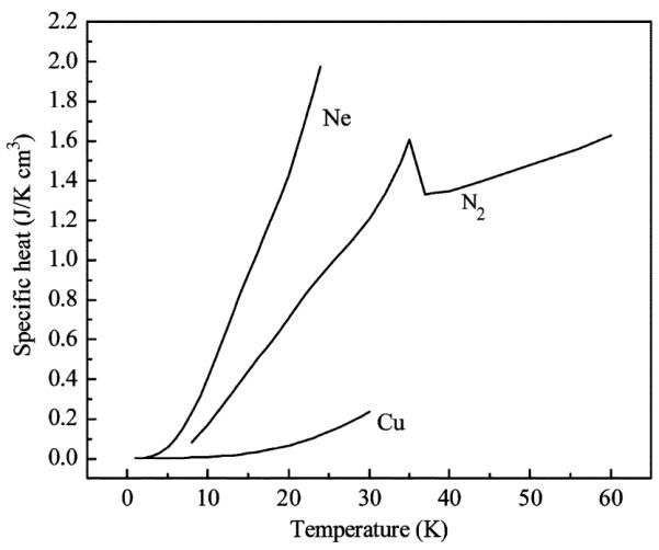
Heat capacity vs. temperature plots of Ne [4], N2 [5] and Cu.
Due to the relatively broad transition between the superconducting and resistive state, or in other words, a small index value n for the MgB2 conductor, unless the magnet runs far below Ic, there is always some resistive heating due to the so-called index voltage, V, at current, I, as given by (1). Conducting the heat away from the conductor is crucial to sustain the conductor at its operating temperature. Table II lists the thermal conductivities of solid Ne [6], N2 [7], and epoxy (Stycast 2850 FT) [8] at 10 K. The thermal conductivities of two cryogens are greater than that of epoxy. If conduction cooling is critical in the winding, it seems better not to cast the winding inside epoxy. Energy disturbances can produce local heating in the winding that may prematurely quench the magnet. Fast thermal diffusion of the surrounding cryogen can also improve the magnet’s stability against transient heat disturbance. In Table II, the thermal diffusivities DT = λ/cp are compared. Note that solid nitrogen at 10 K works better to disperse transient heat than liquid helium at 4.2 K.
TABLE II.
Thermal Properties of Cryogens
|
He (4.2K) |
Solid Ne (at 10K) |
Solid N2 (at 10K) |
Epoxy (at 10K) |
|
|---|---|---|---|---|
| cp(J/cm3 K) | 0.56 | 0.4 | 0.17 | 0.015 |
| (mW/cm K) | 0.2 | 20 | 15 | 4 |
| DT(cm2/s) | 3.5×10⁻⁴ | 5×10⁻² | 8.8×10⁻² | 2.6×10⁻¹ |
From 62 K, the solidification temperature of nitrogen, to 10 K, the density increases by 10%. Solid nitrogen also undergoes a structure phase transition at a temperature of 35.6 K, which is shown in the sharp turn of its heat capacity in Fig. 6. The elastic moduli of solid nitrogen are very similar to those of epoxies such as Stycast 1266. In this sense, solid nitrogen impregnation will prevent the conductor from moving in a strong magnetic field. So far, it is not clear to us if the solid nitrogen uniformly fills the gap between the winding.
V. Test of the Magnet
The magnet can was first filled up with liquid nitrogen. Pumping on the nitrogen lowered its temperature to around 52 K. Then the cryocooler was switched on to further cool the nitrogen. Because of a poor thermal contact between the cryocooler’s second stage and the solid nitrogen can, it usually took 5 to 7 days to reach the lowest temperature of 14 K on the coils. Although the total external heat load to the magnet is less than 1 W, the poor thermal contact thus far prevented the cold body from reaching 10 K, while the temperature of the second stage itself was usually below 7 K. Fig. 7 shows a set of temperature versus time curves recorded during a cool-down sequence.
Fig. 7.
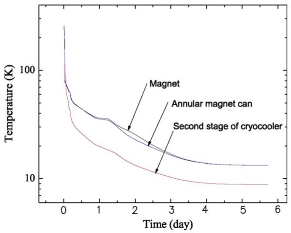
Temperature versus time curves during the cool-down.
Before assembled into the magnet, each coil was individually tested and it successfully reached a current of 100 A. However, in one of the test sequences of the whole magnet, the magnet prematurely quenched at a current of 87.7 A, much lower than 156 A, an estimated critical current for the magnet. At 87.7 A the magnet generated a center field of 0.54 T.
Fig. 8 shows the voltage vs. time plots across individual coils and the magnet current vs. time plot recorded in another test sequence, in which the magnet prematurely quenched at 79 A. The voltage traces clearly indicate that the quench originated in coil #3, located at the very top of the magnet assembly. The traces also indicate that for a period of more than 30 s prior to the quench the magnet was quiescent at a constant current of 79 A.
Fig. 8.
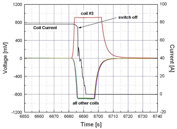
Voltage vs. time plots recorded across each coil and current vs. time plot of the magnet in one test sequence when the magnet quenched at 79 A. Each voltage channel saturates at ±900 mV.
A premature quench in “adiabatic” HTS magnets may be induced by a local or global temperature rise in the winding: this solid nitrogen filled magnet may be considered adiabatic. In an adiabatic HTS magnet, the only heating that may possibly induce a premature quench is either AC losses or resistive heating in the winding. As noted above these coils displayed no resistive voltage when tested individually up to 100 A at 13 K, but resistive voltages, though not discernible from the pre-quench voltage traces shown in Fig. 8, were indeed measured in most of these coils (three exceptions), starting at currents as low as 10 A. Obviously, Joule heating in these resistive coils was too excessive for conduction cooling of the solid nitrogen filled winding. A quench during a quiescent period also implies that dI/dT-induced AC losses are not responsible for this quench. From the respect of conductor development, it is important to distinguish whether the heating is caused by local defects or the overall performance of the wire (small index value n). As a practical approach for our test magnet, made of ten coils, each consisting of 1 km of wire, we made each of them individually replaceable.
VI. Conclusion
A 700-mm bore superconducting magnet was built and operated in our laboratory to demonstrate the feasibility of newly developed MgB2 superconductor wire for fabricating MRI magnets. The magnet, an assembly of 10 coils each wound with a reacted and s-glass insulated wire ~1-km long, was immersed in solid nitrogen. The magnet was designed to operate in the temperature range 10–15 K, maintained by a cryocooler. Tested individually at 13 K, each coil could carry current up to 100 A. When assembled into the magnet, however, some coils became resistive, causing the magnet to prematurely quench at currents ranging from 79 A to 88 A, at which the magnet generated a center field of 0.54 T. These resistive coils must be replaced for the magnet to generate a design center field of 0.61 T at 100 A. Despite the presence of a large volume (50 liters) of solid nitrogen in the cold body, cooldown from 77 K to 10 K went smoothly. To fulfill the potential of MgB2 conductor for large diameter MRI magnet, further development is needed in the following two areas, producing conductor with consistent performance and developing superconducting joints between two conductors.
Fig. 4.
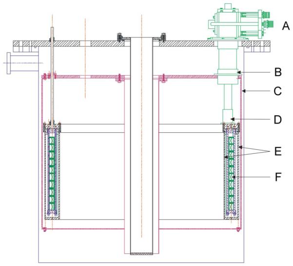
Schematic drawing of a cross section view of the magnet in its cryostat. A: cryocooler, B: the first stage of cryocooler, C: radiation shield, D: the second stage of cryocooler, E: annular can for solid nitrogen, F: coils.
Fig. 5.
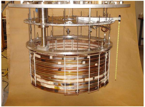
Picture of the magnet with the solid nitrogen can removed.
TABLE I.
Coil Parameters
| Inner Diameter | 773 mm |
| Length | 25.4 mm |
| Turns/layer | 25 |
| Layers | 16 |
| Bare wire diameter | 0.83 mm |
| Diameter with insulation |
1.01 mm |
| Center field for single coil at 100 A |
0.06 T |
| Peak field for single coil at 100 A |
0.71 T |
Acknowledgments
This work was supported by the National Institute of Health.
Footnotes
Color versions of one or more of the figures in this paper are available online at http://ieeexplore.ieee.org.
References
- [1].Tomsic M, Rindfleisch M, Yue J, McFadden K, Phillips J. Overview of MgB2 superconductor applications. Int. J. Appl. Ceram. Technol. 2007;vol. 4(no. 3):250–259. [Google Scholar]
- [2].Iwasa Y, Larbalestier DC, Okada M, Penco R, Sumption MD, Xi XX. A round table discussion on MgB2 toward a wide market or a niche production? A summary. IEEE Trans. Appl. Supperconduc. 2006;vol. 16(no. 2):1457–1464. [Google Scholar]
- [3].Hyper Tech Research, Inc. 1275 Kinnear Road. Columbus, OH, 43212.
- [4].Fenichel H, Serin B. Low-temperature specific heats of solid neon and solid xenon. Phys. Rev. 1966;vol. 142:490–495. [Google Scholar]
- [5].Scott TA. Solid and liquid nitrogen. Phys. Rep. 1976;vol. 27C:89–157. [Google Scholar]
- [6].Weston HT. Temperature and volume dependence of the thermal conductivity of solid neon. Phys. Rev. B. 1984;vol. 29:2709–2716. [Google Scholar]
- [7].Stackowiak R, Sumarokov VV, Mucha J, Jezowsi A. Thermal conductivity of solid nitrogen. Phys. Rev. B. 1994;vol. 50:543–546. doi: 10.1103/physrevb.50.543. [DOI] [PubMed] [Google Scholar]
- [8].Tsai CL, Weinstock H, Overton WC., Jr. Low temperature thermal conductivity of Stycast 2850 FT. Cryogenics. 1978;vol. 18:562–563. [Google Scholar]


