Abstract
Ultrahigh sensitivity detection of particles in solution implies the ability to detect at very low concentrations. At the single-particle level, this is achieved through fluorescence detection, reaching down to single fluorophores. Sensitivity may also be improved by concentrating many particles into a compact cluster, thus “integrating” the signal of many particles. We show how both ways can be combined on an optofluidic chip in a fully planar geometry utilizing counterpropagating liquid-core waveguide modes to form a loss-based optical trap. This all-optical concentrator can increase the concentration of particles by more than 2 orders of magnitude and also provides a convenient, nondispersive means of transport for particle ensembles.
There is a perpetual effort to boost the sensing capabilities of optical detection devices to obtain unambiguous and differentiated information. The goal is to improve the signal-to-noise ratio beyond some acceptable decision threshold with minimal processing effort. In a fluorescence-based detection scheme, there are basically two ways to do this. One way is to increase the signal by strong labeling, to reduce background luminescence from device materials, or to use lock-in modulation techniques. There are drawbacks to this approach. Heavy labeling with multiple fluorophores may interfere with biological viability [1] and may require additional cleaning and separation steps that are not practical for an integrated solution. The restriction to exotic device materials may make the manufacturing process complicated and expensive and may inhibit the incorporation of additional functional components into the analysis platform. Signal modulation and recovery techniques will also severely raise the device cost and the level of complexity in production and operation. The other way is the active concentration of the analyte at the sensing location to gain many orders of magnitude in signal strength by a local increase in particle number density.
There exist a number of examples of separation and concentration [2] techniques for microfluidic devices utilizing dielectrophoretic, acoustic, magnetic, and electrostatic effects and optical chromatography [3–5]. Nonetheless, a truly integrated device capable of simultaneous high sensitivity detection and sample concentration enhancement has been lacking. For highest versatility, it should possess the following properties: continuous operation (unlike “deadend” methods, e.g., filtration), reconfigurability, operational conditions that preserve viability and characteristic properties, conformation with standard sample-preparation steps, and insensitivity to buffer composition and a minimum of experimental parameters to be controlled. All-optically induced forces fulfill all these requirements [6] and stand out as a highly versatile tool in other areas of research (e.g., optical tweezers). To date, most efforts in this direction employed optical fibers or capillaries that are not integrable [7], make use of evanescent fields above integrated waveguides that suffer from limited efficiency in both particle capture and optical signal detection [8], or utilize supplementary, nonoptical forces that introduce additional experimental complexity [4].
Here we propose and demonstrate an all-optical fully planar particle concentrator based on optofluidic, antiresonant reflecting optical waveguide (ARROW) networks [9–13] that is capable of monitoring a fluorescence signal during the aggregation process. The noninvasive nature of this technique is particularly suited for living material and does not put any restrictions on the buffer used. Based on an optical trap, it offers the possibility of transporting a collection of particles without dispersion along the chip for analysis, routing, or further processing, merely through the adjustment of beam powers. Capture of particles can also be accomplished from a continuous flow with unit efficiency and paired with other methods of particle manipulation that could introduce additional discriminative properties [14] or selectivity through particle-specific staining.
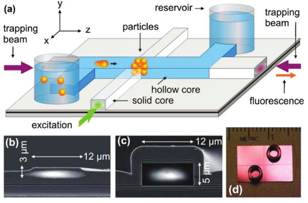
An ARROW is a dielectric layer sequence that defines a highly reflecting surface around a waveguide core and confines light regardless of the indices surrounding the structure [10]. It offers four major advantages over conventional integrated waveguides: structures can be deposited on high-index substrates (here SiO2/SiN on an Si substrate), materials can be chosen to conform with standard lithographic technology, the waveguide properties can be adjusted by the layer thicknesses, and the core may be hollow or liquid filled. The latter is of particular interest here, since it allows copropagaation of guided modes with analyte solution within a common cross section on the micrometer scale over long distances on the order of centimeters, limited only by residual waveguide loss. A network of solid- and liquid-core ARROWs forms the basis of our optofluidic platform (see Fig. 1). Notable features are optical access to the liquid core through solid-core extensions, intersections for local optical excitation and detection, and reservoirs at the channel terminations through which an analyte solution can be introduced into the device.
Fig. 1.

(Color online) (a) Design layout of the ARROW optofluidic analysis platform. Particles are trapped by counterpropagating trapping beams inside the hollow waveguide at an intersection with a solid-core waveguide. (b), (c) Electron micrographs of waveguide cross sections overlayed with guided-beam profiles. (d) Photograph of a chip with reservoirs.
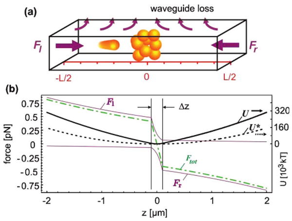
Local-concentration enhancement at a desired location along the channel is achieved using the optical scattering force. Intrinsic propagation loss causes the power and hence the force to decline exponentially on the way through the waveguide [11]. When a second counterpropagating wave is applied, a stable point can be established at which the particle stops and becomes trapped axially as well as transversely owing to gradient forces of both waves. Although similar to the conventional dual-beam trap [15,16], this new trap is based on loss, a waveguide design property, rather than on beam divergence. This reduces the level of setup complexity, improves the device efficiency, extends the longitudinal working range, and offers control at the design level. Since the trapping point is determined by the ratio of the injected powers, it can be shifted to arbitrary locations along the waveguide, allowing easy particle transport (see [11] and [13] for single particles). The transport of particle clusters was observed to be nondispersive, enabling batch processing of tight particle bunches in different physical and chemical microenvironments on the chip where specific reactions can be initiated.
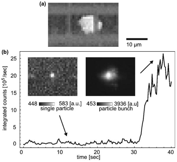
The loss-based trap (LB trap) enables a new all-optical method for locally enhancing particle concentrations: If multiple particles are present in the waveguide channel, they are all subject to the longitudinal scattering force that forms the LB trap. Consequently, particles accumulate in bunches at the trapping locations as shown, for example, for ∼120 1 μm beads (Invitrogen, Tetraspeck, ∼10−4/μm3) in Fig. 3(a). The perfect overlap of the fluidic volume with the optical mode allows one to “sweep up” all particles residing in the waveguide channel. This is a clear advantage over evanescent optical concentrators, whose operation range represents only a fraction of the fluidic volume. In this experiment 2 ×125 mW of IR light (Coherent, Mira 900F at 820 nm) was coupled through single-mode fibers end-to-end into the waveguide of the ARROW chip. The particles were observed from above the chip with a microscope. The particle accumulation process itself is nontrivial. It is enhanced by the effect that upstream particles attenuate the traversing trapping beam. For the outermost particles the local force balance is thus shifted toward the particle bunch. Assuming Mie scattering at low concentration, the forces and the resulting trapping potential are plotted in Fig. 2 for a bunch that extends over Δz = 200 nm around the waveguide center. While the potential for a single particle already forms a well, the shadowing effect on the order of 90% further deepens the trap and accelerates the formation of densely compressed particle bunches. Subsequently, even smaller particles will be attracted and concentrated in the local region of high loss that is created by the initial seeding particles.
Fig. 3.

(a) Concentrated 1 μm particles at a waveguide intersection. (b) Temporal evolution of the fluorescence signal during the optical concentration of 500 nm particles. Insets, fluorescence snapshots of a single particle and the final particle ensemble, single-frame excerpts from Media 1.
Fig. 2.

(Color online) (a) Illustration of the working principle of the loss-based particle concentrator. (b) Spatial dependence of the trapping forces and potentials for a particles ensemble (solid curves, for 120 1 μm microbeads of σscaMie=1.1 μm2) and a single particle (broken curve) with typical loss and power parameters.
From the perspective of particle concentration (total number/total volume), we have thus achieved an increase by a factor of 240. If the powers of the trapping beams are balanced, particles can be collected in the fluorescence detection region at a waveguide intersection for fully planar fluorescence analyis [see Fig. 1(a)]. The concentration enhancement is then accompanied by a growing fluorescence signal. This process is illustrated in Fig. 3 for 500 nm particles (∼10−3/μm3) where the signal enhancement reaches a value of ∼80 for an estimated 170 particles. Fluorescence was excited using a fiber-coupled Nd:YAG laser at 532 nm at microwatt powers and observed through the microscope. The ratio of the channel volume (4000×12×5 μm3) to the fluorescence excitation volume (4×4×6 μm3) provides an estimate for the achievable concentration enhancement, which corresponds to a factor of 2400. The enhancement can be increased even further by supplying additional particles from the reservoir to the excitation volume. The signal in Fig. 3(b) (see also Media 1) remains at low levels as the trap is engaged (t ∼ 10 s) but shows a marked increase once remote particles arrive in the excitation volume (t ∼ 30 s), marking the passage time through one half of the waveguide. The signal increase is rather sudden, since the concentrator beams act on the dispersed particles similar to a snowplow, sweeping up particles along the waveguide as discussed above. For the 1 μm particles, where the number increase was ∼ 120, we notice that the signal enhancement of ∼60 scales sublinearly with the particle number. This we attribute to the shadowing that also affects the excitation light if the particles are large in size or opaque. Some particles of the cluster also reside at the edges of the excitation/detection volume and have a lower probability of detection.
While large, brightly fluorescing particles can be detected without further concentration, one can envision a situation in which the bunching effect can serve as a controllable reaction starter. One example are beads that are surface coated with two reaction agents and are brought into contact by the trap in a matter of seconds rather than relying on slow diffusion.
It is important to recognize the limits of the LB concentrator. These are imposed at low particle numbers (here, <25) in the Mie regime by optical repulsion processes and at higher trapping powers by chaotic particle dynamics [17]. Rayleigh particles, such as silver nanoparticles, on the other hand, tend to arrange into continuous or periodically modulated strings owing to filamentation and self-trapping [18]. It is also expected that the size scaling for the axial confinement Δzrms will nontrivially deviate from the single-particle scaling law of Δzrms ∼1/volume (polarizability) [13] owing to such interparticle optical forces. The details of these processes are beyond the scope of this Letter.
To summarize, we have introduced an all-optical particle concentrator capable of increasing the detection limit of small, weakly fluorescing particles. The concentrator requires virtually no preparational steps and can be reconfigured and operated continuously. Within a simple design, it thus performs most steps for on-chip ultrasensitive particle detection and processing.
Acknowledgments
This work was supported by the National Institutes of Health (NIH)/National Institute of Biomedical Imaging and BioEngineering under grant R01EB006097, the National Science Foundation (NSF) under grants ECS-0528730 and ECS-0528714, and the W M. Keck Center for Nanoscale Optofluidics at the University of California Santa Cruz.
References
- 1.Berman HM, Young PR. Annu Rev Biophys Bioeng. 1981;10:87. doi: 10.1146/annurev.bb.10.060181.000511. [DOI] [PubMed] [Google Scholar]
- 2.Auroux PA, Iossifidis D, Reyes D, Manz A. Anal Chem. 2002;74:2637. doi: 10.1021/ac020239t. [DOI] [PubMed] [Google Scholar]
- 3.Song S, Singh A. Anal Bioanal Chem. 2006;384:41. doi: 10.1007/s00216-005-0206-3. [DOI] [PubMed] [Google Scholar]
- 4.Terray A, Ladouceur HD, Hammond M, Hart SJ. Opt Express. 2009;17:2024. doi: 10.1364/oe.17.002024. [DOI] [PubMed] [Google Scholar]
- 5.Cordovez B, Psaltis D, Erickson D. Appl Phys Lett. 2007;90:024102. [Google Scholar]
- 6.Buican TN, Smyth MJ, Crissman HA, Salzman GC, Stewart CC, Martin JC. Appl Opt. 1987;26:5311. doi: 10.1364/AO.26.005311. [DOI] [PubMed] [Google Scholar]
- 7.Mandal S, Erickson D. Appl Phys Lett. 2007;90:184103. [Google Scholar]
- 8.Yang AHJ, Moore SD, Schmidt BS, Klug M, Lipson M, Erickson D. Nature. 2009;457:71. doi: 10.1038/nature07593. [DOI] [PubMed] [Google Scholar]
- 9.Hawkins A, Schmidt H. Microfluid Nanofluid. 2007;4:17. doi: 10.1007/s10404-007-0194-z. [DOI] [PMC free article] [PubMed] [Google Scholar]
- 10.Schmidt H, Hawkins A. Microfluid Nanofluid. 2008;4:3. doi: 10.1007/s10404-007-0199-7. [DOI] [PMC free article] [PubMed] [Google Scholar]
- 11.Measor P, Kühn S, Lunt EJ, Phillips BS, Hawkins AR, Schmidt H. Opt Lett. 2008;33:672. doi: 10.1364/ol.33.000672. [DOI] [PMC free article] [PubMed] [Google Scholar]
- 12.Yin D, Barber JP, Hawkins AR, Schmidt H. Appl Phys Lett. 2005;87:211111. [Google Scholar]
- 13.Küehn S, Measor P, Lunt EJ, Phillips BS, Deamer DW, Hawkins AR, Schmidt H. Loss-based optical trap for on-chip particle analysis. Lab Chip. doi: 10.1039/b900555b. to be published. [DOI] [PMC free article] [PubMed] [Google Scholar]
- 14.Jonáscaron A, Zemánek P. Electrophoresis. 2008;29:4813. doi: 10.1002/elps.200800484. [DOI] [PubMed] [Google Scholar]
- 15.Ashkin A. Phys Rev Lett. 1970;24:156. [Google Scholar]
- 16.Cran-McGreehin S, Krauss TF, Dholakia K. Lab Chip. 2006;6:1122. doi: 10.1039/b605237a. [DOI] [PubMed] [Google Scholar]
- 17.Kawano M, Blakely JT, Gordon R, Sinton D. Opt Express. 2008;16:9306. doi: 10.1364/oe.16.009306. [DOI] [PubMed] [Google Scholar]
- 18.Conti C, Ruocco G, Trillo S. Phys Rev Lett. 2005;95:183902. doi: 10.1103/PhysRevLett.95.183902. [DOI] [PubMed] [Google Scholar]


