Abstract
Elastography is an emerging imaging technique that focuses on assessing the resistance to deformation of soft biological tissues in vivo. Magnetic resonance elastography (MRE) uses measured displacement fields resulting from low-amplitude, low-frequency (10 Hz–1 kHz) time-harmonic vibration to recover images of the elastic property distribution of tissues including breast, liver, muscle, prostate, and brain. While many soft tissues display complex time-dependent behavior not described by linear elasticity, the models most commonly employed in MRE parameter reconstructions are based on elastic assumptions. Further, elasticity models fail to include the interstitial fluid phase present in vivo. Alternative continuum models, such as consolidation theory, are able to represent tissue and other materials comprising two distinct phases, generally consisting of a porous elastic solid and penetrating fluid. MRE reconstructions of simulated elastic and poroelastic phantoms were performed to investigate the limitations of current-elasticity-based methods in producing accurate elastic parameter estimates in poroelastic media. The results indicate that linearly elastic reconstructions of fluid-saturated porous media at amplitudes and frequencies relevant to steady-state MRE can yield misleading effective property distributions resulting from the complex interaction between their solid and fluid phases.
Keywords: Finite-element method (FEM), magnetic resonance elastography (MRE), poroelasticity, reconstructive imaging
I. INTRODUCTION
Elastography [1], [2] generally assumes that biological tissues can be modeled as linearly elastic, single phase (i.e., solid), isotropic, nearly incompressible media. Magnetic resonance elastography (MRE) [2] has emerged as a noninvasive, quantitative imaging technique that often employs these assumptions to estimate the elastic properties of biological tissues including breast [3]–[5], liver [6], [7], muscle [8]–[10], and prostate [11]. Recently, however, there has been interest in evaluating the time-dependent deformation of cartilage [12], brain [13], [14], and lymphedematous tissues [15], whose behavior is not well described by linear elasticity. Driving this interest is the recognition that many soft tissues comprise separate solid and fluid phases.
Brain tissue has long been acknowledged to display time-dependent deformation behavior [16]. Studies performed by Miller et al. [17] indicate that use of linear viscoelastic theory is inappropriate for modeling brain deformation. While theoretical nonlinear viscoelastic mechanical models have been found to agree reasonably well with deformation response at higher strain rates [18], these models fail to include the effects of the interstitial fluid phase present in tissue. Recent studies by Franceschini et al. [19], and Cheng and Bilston [20] have shown that incorporation of poroelastic constitutive relations into combined tissue models is better at capturing the total deformation behavior of brain. Further, Weaver et al. [21] have investigated the relationship between reconstructed elastic parameters and brain interstitial fluid pressure (IFP) in porcine subjects. The average shear modulus over the brain was observed to decrease with time after anesthesia, following a general trend of decreasing arterial blood pressure. This trend continued after euthanasia and was found to correlate with decreasing brain IFP. Although the deformation behavior of the brain was demonstrated to be affected by IFP, failure to produce repeatable elastic parameter estimates may have been, in part, due to the inability of the linearly elastic model to appropriately interpret measured data that are better described by a more complete set of governing equations.
Poroelastic models have been used to approximate the transient mechanical behavior of porous media such as tofu [22], [23]. Originally developed for soil mechanics [24], [25], poroelasticity models the deformation of a solid matrix in which mechanical displacement is affected by the resistance to fluid flow through a network of interconnected pores under a pressure gradient. In 2001, Konofagou et al. [26] demonstrated the potential of employing ultrasound elastography to image the deformation of poroelastic materials during stress relaxation. The mechanism driving the time-dependent behavior was attributed to fluid flow occurring in the material as a result of pressure gradients induced by localized compression. Though these methods show considerable potential, displacements measured using ultrasound techniques are generally unstable in the off-axis directions and in the presence of uncontrolled tissue motion [27]. In addition, ultrasound methods inherently lack the ability to investigate deep tissue structures including brain, to which access is limited by the closed cranium. MRE, on the other hand, offers the opportunity to measure displacements in three directions with equal accuracy and precision. Further, it is likely that poroelastic deformation phenomena observed with ultrasound may also be captured using MRE, and that these effects may prove to be particularly important when tissues are perturbed dynamically.
Poroelastic modeling of the brain using finite elements has already been employed to study hydrocephalus and edema [28]–[30], as well as brain-shift and interstitial pressure fluctuations occurring during stereotactic neurosurgery [31]–[35]. While successful in capturing quasi-static deformation, no information exists regarding the ability of these models to accurately describe the motion and pressure distribution resulting from low-frequency harmonic vibration. Lack of model equations that modify the relationship between force and displacement due to the presence of a pressure gradient may result in a misrepresentation of the “true” elastic parameter distribution. Presented here is an exploration of the effect of assuming a purely elastic model on the distribution of reconstructed shear modulus given displacement fields obtained in fluid-saturated porous media during steady-state MRE. The results show that systematic over-/underestimation of the shear modulus of the solid matrix is influenced by the resistance to volumetric deformation caused by pressure gradients that develop in the pore fluid. This type of response is expected to be sensitive to the mechanical excitation frequency, length scale, and inherent flow properties within a region of interest. Understanding and ultimately accounting for those effects is likely to be critical to the success of clinical MRE in tissues that exhibit strong poroelastic mechanical behavior. The goal of this paper is to emphasize the differences observed between the poroelastic and estimated elastic response in fluid-saturated porous media similar to tofu, and highlight the inability of a purely elastic reconstruction to account for the observed poroelastic effects at frequencies applicable to MRE.
II. METHODS
Three-dimensional (3-D) finite-element method (FEM) algorithms were developed by Perriñez et al. [36] to solve both the elastic and poroelastic equations for the respective real-and complex-valued displacement fields under time-harmonic forcing. Estimates of the elastic parameter distribution for the simulated data were subsequently obtained in the absence of measurement noise by providing the displacement fields to the finite-element-based nonlinear inversion scheme described by Van Houten et al. [37], [38]. The resulting elastic parameter distributions were compared with the model input values in order to identify systematic misinterpretations of the true poroelastic property distribution due to the underlying data model mismatch. The effective shear modulus distributions were then compared to distributions of the absolute difference in volumetric strain between elastic and poroelastic models, the magnitude of the pore pressure, and the magnitude of the gradient in pore pressure. The mechanical properties used in the FEM solutions correspond to those of commercially available tofu (Mori-Nu Silken Extra-Firm, Morinaga Nutritional Foods, Inc.), which were measured using a TA Q800 dynamic mechanical analyzer (TA Instruments) and a custom-built confined-compression device. The tofu was modeled as a linear, homogeneous, isotropic, porous medium consisting of a solid elastic matrix and viscous penetrating fluid.
A. Material Properties
Tofu has been recognized to behave as a fluid-saturated porous material [22], [23] that exhibits acoustic properties similar to those of some soft biological tissues [39]. Though ultrasound poroelastography has been successful in producing time-dependent lateral-to-axial strain ratio images (poroelastograms) of tofu [22] and lymphedematous tissues [15] under sustained axial loading, little is known about the response of these materials to the dynamic loading that would be experienced during steady-state MRE.
To better understand the differences between the long-term (quasi-static) and acute (dynamic) material response, a series of mechanical tests was performed on cylindrical disks of commercially available tofu obtained from the center of spatially varying core samples taken from four different slabs. The elastic modulus of the solid matrix was determined by unconfined, quasi-static compression (0.05 N/min) of the cylindrical samples (diameter 28 mm, 9 mm thick), which were compressed between two flat, impermeable plates that allowed fluid to flow freely through the cylinder sidewall. Compressing the material at a sufficiently slow rate allowed the fluid to flow through the pores with negligible resistance and without contributing to the bulk material stiffness. Removing the dependence on time ensured that the measured resistance to deformation was a function of the material properties of the porous solid alone. The quasi-static elastic modulus for the tofu matrix in each slab was determined to be between 6 and 14 kPa from data in the linear region with an average variation of about 3% for samples originating from the same slab.
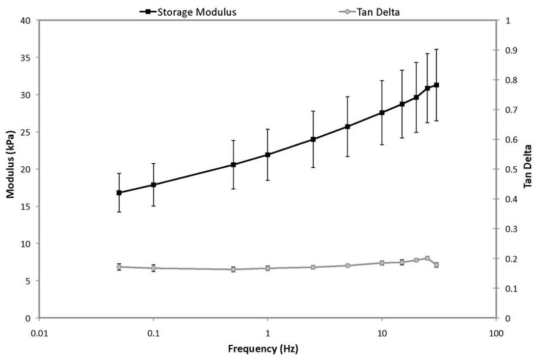
Employing the same experimental setup used to measure the quasi-static modulus, the dynamic viscoelastic properties [storage modulus and tan(δ)] of similar cylindrical samples were determined by applying an oscillating axial compression at frequencies ranging between 0.05 and 100 Hz. A small preload of 0.01 N was applied to ensure that the samples remained in compression throughout the testing procedure. A typical plot of the dynamic viscoelastic properties of tofu as a function of frequency is provided in Fig. 1. This graph shows the material to be predominately elastic, with a relatively small tan(δ), which is approximately constant over the frequency range tested. The storage modulus was observed to increase with frequency between 0.05 and 35 Hz, possibly, in part, due to increased pressure in the material’s pores resulting from insufficient time to allow for fluid flow during the compression cycle. Viscoelasticity of the solid matrix may have also contributed to the observed behavior. Data beyond 35 Hz were not included as this region was dominated by resonance resulting from inertial effects. Comparison of the storage modulus data with the estimated quasi-static elastic modulus suggests that tofu, when subjected to compressive loading at frequencies relevant to MRE (O(102 ) Hz), may appear to be significantly stiffer than would be predicted by a linear elasticity analysis based on the quasi-static curve. Further, a preliminary investigation of the flow parameters relevant to the FEM model was performed using a custom-built confined-compression device. Core samples (diameter 0.5 in, 2 in long) were subjected to quasi-static confined compression where fluid was allowed to leave through a porous filter. By fitting the time evolution of displacement to the analytic solution for 1-D consolidation of poroelastic media [24], the hydraulic conductivity (κ) of the tofu was estimated to be O(10−9 ) m3 · s/kg. The bulk material density (ρ) was determined from mass and volume measurements to be approximately 1020 kg/m3. The material porosity (ϕ) was found to be about 0.2 based on analysis of stained histological sections.
Fig. 1.
Representative frequency sweep of the viscoelastic properties of extra firm silken tofu undergoing unconfined compression.
B. Mathematical Model
The equations used to model the time-harmonic deformation of poroelastic tofu are based on those developed by Biot in 1956 [40], [41] as an extension of his earlier work involving quasi-static poroelasticity [24]. The frequency response of Biot’s dynamic poroelasticity equations was later explored by Cheng et al. [42]. The dynamic parameters used by Cheng et al. were formulated to be consistent with the notation in Biot’s earlier work [24], which was written in terms of total stress (σ) and pore pressure (p) as opposed to “partial solid stress” and “partial fluid stress.” Following Cheng’s description, which assumes full saturation, the coupled set of partial differential equations (PDEs) governing the material behavior under time-harmonic vibration and in the absence of body forces can be expressed as
| (1a) |
| (1b) |
where the vector ū contains the complex-valued x-, y-, and z-components of displacement, and p̄ is the complex fluid pressure. Here, the overbar (¯) indicates the frequency-dependent part of the dependent variable after subsequent removal of the time-harmonic factor. The parameters α,R, φ, and β are defined as
| (2) |
| (3) |
| (4) |
| (5) |
where α is the Biot effective stress coefficient, R is a measure of the change in water content (ζ) for a given change in water pressure (p), and ϕ is the material porosity. The densities of the bulk material and pore fluid are given by ρ and ρf, respectively. The parameter ρa is defined as the apparent mass density and is a measure of the work done by relative motion between the solid and fluid phases. In addition, the matrix shear modulus and excitation frequency are represented by μ and ω, while ν and νu designate the drained and undrained Poisson ratios, respectively. The parameterB is often referred to as the Skempton pore pressure coefficient [43] and is defined as the ratio of change in pore pressure to the change in applied stress under no flow conditions (ζ = 0). In essence, B is a measure of how an applied load is distributed between the solid matrix and the pore fluid, assuming a value between 0 and 1 [44]. Furthermore, the hydraulic conductivity (κ) is assumed to be isotropic and spatially uniform. For simplicity, we neglect any potential frequency dependence of parameters κ and ρa. We may further simplify this model by assuming that the individual material constituents are incompressible, as given by K/Ksolid ≪ 1 and K/Kfluid ≪ 1, where K is the bulk modulus of the porous media, and Ksolid and Kfluid denote the bulk modulus of the matrix material and pore fluid, respectively. Following the development of the constitutive relations as outlined by Detournay and Cheng [45], and Schanz and Diebels [46], we rewrite the parameters α and R in terms of the bulk moduli
Carrying through the assumption of incompressible constituents, the governing equations can be rewritten as
| (6a) |
| (6b) |
C. Finite-Element Formulation
Neglecting gravity and the presence of any pressure source, the weak form of (6) with scalar weighting functions ϕi(x, y, z) is written as
| (7a) |
| (7b) |
An alternate weak form of (7) is obtained through application of the divergence integral identities
| (8) |
| (9) |
yielding
| (10a) |
| (10b) |
where ∮ denotes integration over the domain boundary and n̂ is the outward-pointing normal vector. The 3-D stress–strain relations for a linearly elastic solid containing an infiltrating pore fluid can be written in the following form [47]:
| (11a) |
| (11b) |
where σE is the Cauchy stress tensor, λ is a Lame constant, and ε is the infinitesimal strain tensor. Expanding the first term in (10a) we achieve
| (12) |
Applying the identity
| (13) |
the second term in (12) becomes
| (14) |
Substituting (14) and simplifying, (12) is reduced to
| (15) |
In order to quantify the effect of poroelastic displacement fields on our current linearly elastic reconstruction algorithm, it was necessary to develop a 3-D FEM solver for the solution to the dynamic poroelasticity problem described by (6). The 3-D FEM formulation requires that the approximate solution variables û, v̂, ŵ, and p̂ be expanded on a basis set (ϕ), yielding
| (16) |
| (17) |
| (18) |
| (19) |
Developing the Galerkin weak form of (10) leads to a system of equations in terms of an unknown solution vector {χ̂} under the influence of a known forcing vector {b}
| (20) |
where {χ̂} is defined as
| (21) |
and where {b} is defined as
The system stiffness matrix [A] is composed of integrals of the basis functions, their derivatives, and the continuum’s physical properties [48], and is described by the set of subelements
Given the nature of these equations, the resulting system is sparse, complex, and unsymmetric. For these reasons, it was solved using multifrontal massively parallel sparse direct solver (MUMPS), a freely available package based on parallel processing software developed during the Esprit IV European project PARASOL (1996–1999) [49]–[51]. Solutions to the equations of motion for a linearly elastic continuum were obtained via the finite-element formulation described by Van Houten et al. [38] and solved using MUMPS, yielding a real-valued displacement field. Displacements generated through the solution of (20) were supplied to a reconstruction algorithm based on linear elasticity, requiring a real-valued displacement field (i.e., all points within the domain have a 0° or 180° phase value) extracted from the poroelastic solution as
| (22) |
where Ai and Pi represent the amplitude and phase in the x-, y-, and z-directions derived from the poroelastic model. This procedure is also a required step in the postprocessing of clinical data reconstructed with linear elasticity and is used to identify the direction of motion in the case where the imaginary part of the measured data is small (as would be the case if the material were purely elastic). Numerical solutions were computed on a Linux cluster comprising 75 PSSC AMD Opteron nodes, each containing two dual-core Opteron CPUs.
D. Numerical Simulations
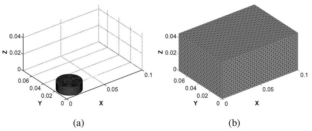
Simulated data was generated for two different geometries (Fig. 2), a 28-mm-diameter, 10-mm-thick cylindrical disk consistent with the dimensions of the tofu core samples used in mechanical testing, and a 10 × 7.5 × 4.5 cm rectangular prism corresponding to the dimensions of the unmodified tofu slab.
Fig. 2.
3-D tetrahedral finite-element mesh used for analysis of the (a) tofu cylinder (15 998 nodes, 81 159 elements) and (b) tofu slab (45 749 nodes, 259 200 elements).
The boundary conditions imposed on the cylindrical disk were those of: 1) unconfined compression and 2) unconfined shear. For the compression case, in an attempt to simulate the conditions experienced during mechanical testing, the cylinder base was fixed in all directions (u = v = w = 0), while the top was fixed in the x- and y-directions and excited by an applied stress (20 Pa) varying sinusoidally in the z-direction. The magnitude of the applied stress was determined as the value required to produce deformations on the order of those measured by MRE (O(10−6 ) m). The force applied at each node was calculated by integrating over the participating boundary elements. Consistent with the experimental setup, fluid flow was allowed through the exposed sidewall (p = 0 Pa) but not through the top or bottom surfaces (∂p/∂n = 0 Pa). For the case of shear, the conditions applied were intended to simulate unconfined shear excitation of the tofu cylinder fixed to an impermeable plate. Unidirectional excitation (10 µm) was imposed at the base along the x-direction (v = w = 0) and a zero-stress condition was applied to all other surfaces (∂ū/∂n = 0). Fluid flow was allowed only through the top and sidewall. The slab geometry was also excited (50 µm) in unconfined shear at its base along the x-direction. As with the tofu cylinder, a zero-stress condition was applied to the top and sides of the slab while fluid flow was allowed only through the exposed surfaces. In all cases, the excitation frequency was 100 Hz. The dynamic elasticity and poroelasticity problems were solved using the MUMPS-based FEM implementation described in Section II-C. Inverse calculations based on the elastic model were performed on the same mesh and without noise. This idealized case was used to asses the systematic misinterpretation of the poroelastic displacement data by the reconstruction algorithm. The relevant parameters for both models are provided in Table I.
TABLE I.
Model Parameters
| Simulation | E | μ | ν | ϕ | κ | ρ | ρf | ρa |
|---|---|---|---|---|---|---|---|---|
| Elastic | 12 kPa | 4.138 kPa | 0.45 | − | − | 1020 kg/m3 | − | − |
| Poroelastic | 12 kPa | 4.138 kPa | 0.45 | 0.20 | 1e-9 m3s/kg | 1020 kg/m3 | 1000 kg/m3 | 150 kg/m3 |
III. RESULTS
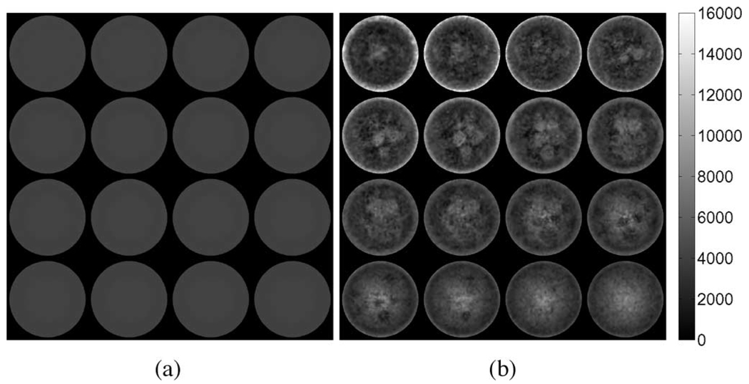
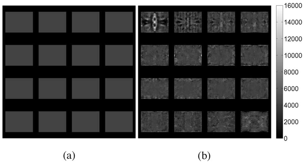
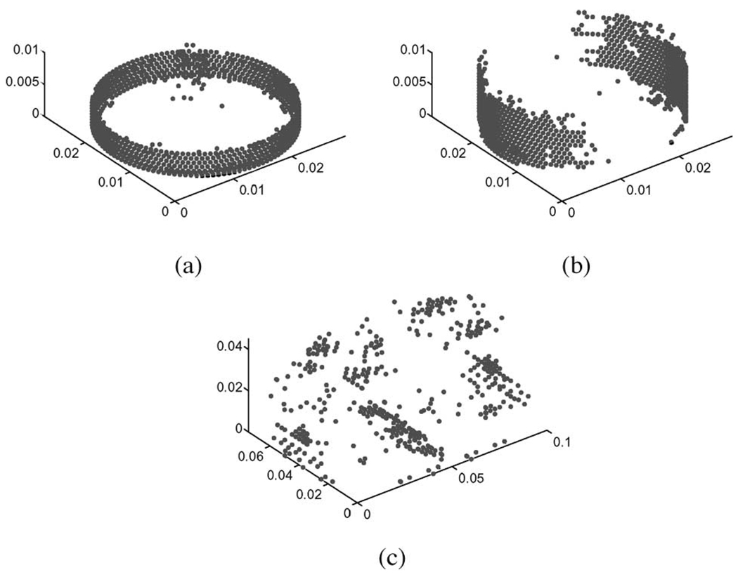
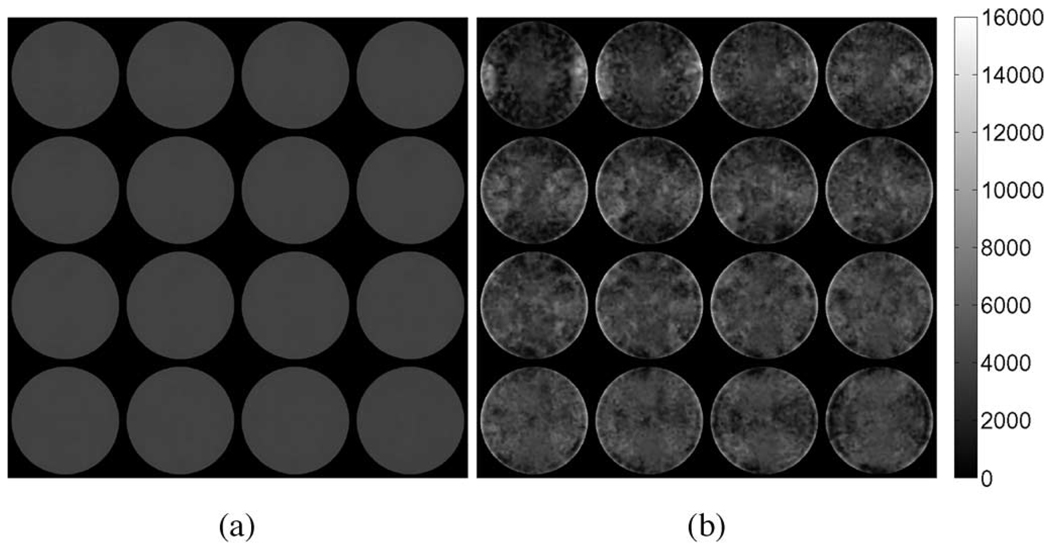
To visualize the results, the elastic parameter reconstructions were interpolated onto 16 2-D slices along the z-axis (Fig. 3–Fig. 5). The bottom slices begin in the upper left-hand corner of the image and continue left-to-right with the topmost slice occurring in the lower right. A summary of the results for the tofu cylinder and the tofu slab is provided in Table II. The values for average shear modulus and standard deviation were computed across the entire problem domain. Reconstructions obtained from elastic displacement fields were found to be consistent with the values used in the model inputs. Reconstructions obtained from the poroelastic displacement fields, however, contain anomalous regions of high and low shear modulus, regardless of actuation method. In the case of the tofu cylinder, the maximum shear modulus overestimate was found to be 5.9 times greater in compression, and 5.0 times greater in shear than that of the input value. For the tofu slab, the maximum overestimation was found to be 4.4 times that of the input value. Overestimates for the tofu cylinder undergoing compression appeared to be uniformly distributed along the mesh perimeter at the base, while overestimates for the cylinder undergoing shear excitation appeared to be concentrated on opposing sides of the mesh. For the tofu slab, the spatial distribution of shear modulus overestimates was more complex, yet still contained patterning consistent with shear excitation. It should be noted that the horizontal in-plane axes of the interpolated images correspond to the global x-direction (i.e., the direction in which shear displacement was applied). Fig. 6 provides images indicating nodal locations where the estimated shear modulus value for the poroelastic input data is greater than or equal to 100% of the true value for each case.
Fig. 3.
Interpolated linear-elasticity-based shear modulus reconstructions for the simulated tofu cylinder in compression obtained from the respective (a) elastic and (b) poroelastic displacement fields. Axial excitation applied in the z-direction corresponds to the out-of-plane direction in these images.
Fig. 5.
Interpolated linear-elasticity-based shear modulus reconstructions for a simulated tofu slab obtained from (a) elastic and (b) poroelastic displacement fields. Shear excitation applied in the x-direction corresponds to the horizontal direction (left–right) in these images.
TABLE II.
Results From Linear-Elasticity-Based Shear Modulus Reconstruction
| tofu cylinder (compression) | tofu cylinder (shear) | tofu slab (shear) | ||||
|---|---|---|---|---|---|---|
| Simulation | Avg. [kPa] | Std. Dev. [kPa] | Avg. [kPa] | Std. Dev. [kPa] | Avg. [kPa] | Std. Dev. [kPa] |
| Elastic | 4.138 | ± 1.283 × 10⁻⁴ | 4.138 | ± 1.785 × 10⁻⁴ | 4.138 | ± 6.523 × 10⁻⁴ |
| Poroelastic | 5.399 | ± 2.537 | 3.867 | ± 2.495 | 4.116 | ± 1.334 |
| H0: μe = μpe | (p < 0.0001) | (p < 0.0001) | (p < 0.001) | |||
Fig. 6.
Nodal locations containing reconstructed shear modulus values obtained from poroelastic displacement fields greater than or equal to 100% of the true value for the tofu cylinder in (a) compression, (b) shear, and (c) tofu slab.
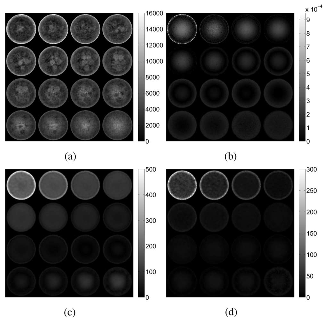
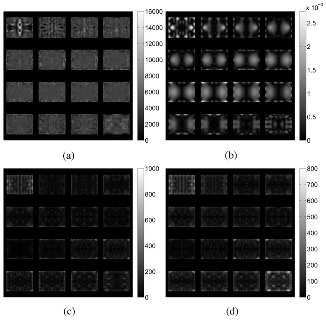
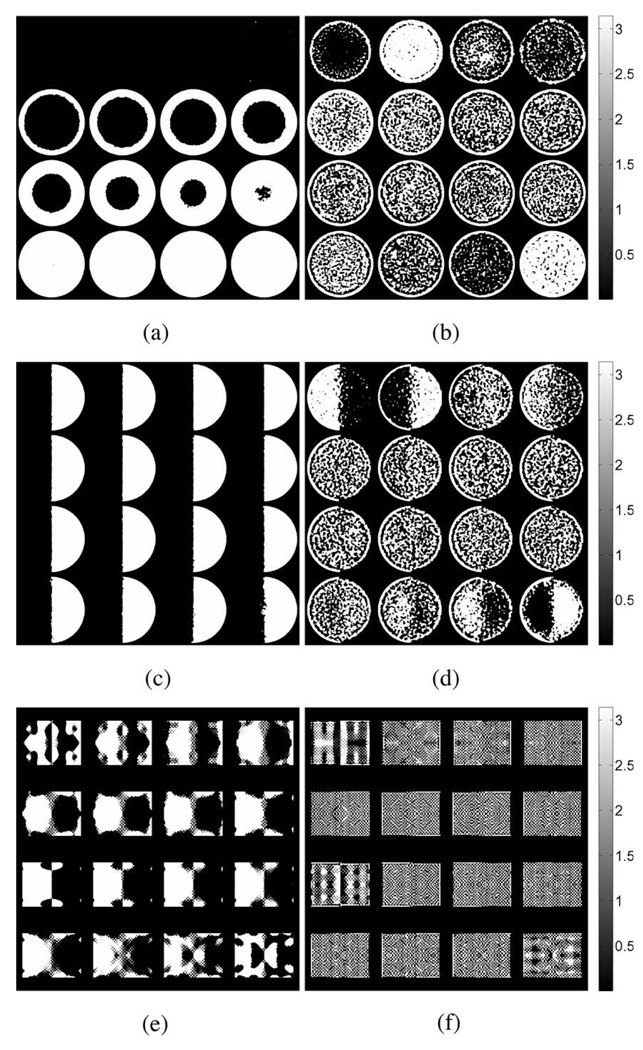
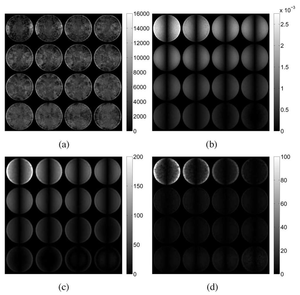
From (6a), it is clear that Navier’s equations of motion for a linearly elastic solid are modified by the presence of a gradient pressure and a nonzero fluid density. Further, the flow of fluid through the porous material described in (6b) is coupled to the matrix deformation through the divergence of the displacement field (∇ · ū) or volumetric strain. Given that the displacement fields generated by an elastic forward solver are inherently real-valued, while those generated by the poroelastic forward solver are complex, simply comparing their amplitudes is not sufficient to explain the differences observed in the resulting reconstructions as the phase of each component of displacement plays an important role. For this reason, distributions of the absolute difference in volumetric strain between the elastic and poroelastic models, the magnitude of the pressure field, and the magnitude of the gradient in pressure were computed and are presented for each case in Fig. 7–Fig. 9 against the appropriate shear modulus distribution, respectively. In addition, the phase of the volumetric strain computed from the elastic and real parts of the poroelastic displacement fields for each case is presented in Fig. 10. Qualitative inspection of Fig. 10(a) and (b) indicates that differences in spatial variation in the phase of the volumetric strain for the tofu cylinder in compression correlate with the presence of effective shear modulus estimates at the base. Similarly, the most striking differences in phase for the tofu cylinder in shear [Fig. 10(c) and (d)] occur on opposing sides along the length of the mesh. In both cases, the regions are found to be in agreement with the nodal distribution shown in Fig. 6(a) and (b). The plots for the tofu slab presented in Fig. 10(e) and (f) show intricate phase distributions that result from the presence of multiple wavelengths. Still, shear modulus overestimates appear to correspond with phase differences occurring at the top and bottom of the mesh in locations where clear patterns are discernible.
Fig. 7.
(a) Reconstructed shear modulus (in pascals), (b) absolute difference in volumetric strain, (c) pressure magnitude (in pascals), and (d) magnitude of the gradient in pressure (in pascals per meter) for the tofu cylinder experiencing unconfined compression.
Fig. 9.
(a) Reconstructed shear modulus (in pascals), (b) absolute difference in volumetric strain, (c) pressure magnitude (in pascals), and (d) magnitude of the gradient in pressure (in pascals per meter) for the tofu slab experiencing unconfined shear.
Fig. 10.
Interpolated views of the phase of the volumetric strain for both the elastic (left) and real parts of the poroelastic data (right). Images are provided for [(a) and (b)] the tofu cylinder in compression, [(c) and (d)] the tofu cylinder in shear, and [(e) and (f)] the tofu slab. Units are given in radians.
IV. DISCUSSION
Experimental measurements on tofu samples show a considerably larger stiffness (modulus) during dynamic testing relative to static, suggesting that resistance to fluid motion may have a significant impact on the resulting deformation behavior of tofu and other poroelastic materials. These data indicate that MRE, which elicits a dynamic response, will produce different mechanical property results than would be expected from static tests such as indentation.
Agreement between reconstructed shear modulus and actual (input) modulus values is dependent on whether the mathematical model used in the reconstruction agrees with that used to generate the data. The numerical simulations show that shear modulus reconstructions obtained from elastic displacement fields in both the cylindrical disc and slab geometries yielded accurate and precise parameter distributions as expected because of the agreement between the mechanical model used in the inversion and that used to generate the synthetic data. On the other hand, reconstructions performed using poroelastic displacement fields appear to exhibit systematic shear modulus overestimates as well as underestimates. Qualitative inspection of Figs. 7 and 8 indicates that regions of higher predicted shear modulus correspond with regions of high nodal pressure and pressure gradient, in agreement with the observations reported by Weaver et al. [21]. In addition, regions of high pressure gradient corresponded to areas where significant differences in volumetric strain occurred between the two models. This is because these regions experienced time-dependent fluid flow invoked by conditions of rapidly changing volume that served to resist deformation, producing a gradient in pressure. Applying this same rationale to the case of the tofu slab (Fig. 9) again indicates that the regions with the greatest difference in volumetric strain correlate with regions of high pressure gradient and over-/underestimated shear modulus. While distinct patterning is apparent, it is clear that the deformation behavior across the simulated phantom is more complicated and harder to interpret than that observed in the tofu cylinder. This behavior is attributed to the complex motion patterns, including resonance and surface wave propagation, owing to the large size of the problem domain relative to the mechanical wavelength involved. Poroelastic data containing significant imaginary components in the displacement and pressure fields indicate the presence of time-harmonic pressure and elemental volume changes that are likely to occur out of phase with respect to the equivalent elastic data, thus requiring a different metric to accurately predict regions of artifactual shear modulus values. Using (22) to obtain the real-valued displacements from the fully complex data can have a significant effect on the spatial distribution of the phase of the volumetric strain for the resulting time-harmonic field. From the images presented in Fig. 10, it is apparent that simply taking the real-part of the complex displacement data is not sufficient to capture a representative displacement field for the purposes of MRE reconstruction. Processing the data in this way can disrupt the smooth distribution of phase across the problem domain, thereby invoking additional artifactual deformation behavior, which may exacerbate the data model mismatch due to the poroelastic effects within a region of interest.
Fig. 8.
(a) Reconstructed shear modulus (in pascals), (b) absolute difference in volumetric strain, (c) pressure magnitude (in pascals), and (d) magnitude of the gradient in pressure (in pascals per meter) for the tofu cylinder experiencing unconfined shear.
In addition, it is important to note that the spatial distribution of the estimated elastic parameters obtained from poroelastic input data will likely vary with a number of mechanical and geometrical parameters, including density, hydraulic conductivity, length scale, pressure boundary conditions, as well as the frequency and amplitude of vibration. Differences between the actual and recovered shear modulus for the poroelastic material are influenced by differences in the perceived stiffness of the material. Stiffness is the relationship between force and displacement. In linear elasticity, there is a direct relationship between stiffness and modulus, although that relationship is more complicated for 3-D stress fields, such as those being treated here. In poroelasticity, however, the presence of time-dependent fluid flow and related pressure gradients modifies the stiffness–modulus relationship. Boundary conditions also affect the deformation behavior of the material. Unlike simple elasticity where a solution for the displacement field requires knowledge of only the displacement or the stress vector at each node on the boundary, a solution to the poroelastic forward problem requires additional knowledge of the pore pressure or its gradients everywhere on the boundary. If fluid flow is restricted by low hydraulic conductivity or by impermeable boundaries, displacement can be substantially smaller than would be expected in the elastic case under the same loading conditions, even though the modulus of the material may remain unchanged. In addition, the expression of this phenomenon in the distributions presented here is likely influenced by the symmetry of both the geometry and excitation mode, especially at the boundaries. Modulus artifacts observed in vivo are expected to occur throughout the volume due to nonuniform excitation and be more pronounced at anatomical boundaries, which limit/prevent fluid flow.
Owing to the complex nature of tissue composition, it is likely that viscoelasticity may also contribute in part to the time- and frequency-dependent deformation behavior observed in tofu, and in normal and diseased tissue. Therefore, viscoelastic material models should be considered in future developments. While viscoelastic reconstructions do not include a fluid phase and cannot take into account pore pressure changes in tissue, use of the fully complex dataset should compensate for some of the shortcomings of a purely elastic model and may be able to capture some of the effects of poroelasticity. Given the significant inaccuracies that can occur in recovering elastic properties of poroelastic tissue using conventional linearly elastic MRE, further investigation is warranted leading to the development of a reconstruction algorithm that incorporates the poroelastic constitutive relations.
V. CONCLUSION
Results from this investigation suggest that shear moduli obtained from common linear-elasticity-based parameter reconstructions of displacements fields measured in fluid saturated media may not be representative of the true solid matrix parameter distribution. Further, harmonic excitation of simulated poroelastic media was found to produce a signature in the displacement fields on time scales relevant to MRE but too short for significant bulk fluid flow to occur. Here, the observed poroelastic effect is related to the resistance to volumetric deformation of the solid matrix in the presence of pressure gradients that develop in the pores; the significance of this will likely change with frequency, length scale, and hydraulic conductivity. Clinically, these findings are relevant in that useful diagnostic information obtained from MRE reconstructions will depend on either the absolute or relative estimated parameter values between normal and diseased tissues. While viscoelastic effects in the solid matrix are likely to augment the complex deformation behavior observed in simulation, it is clear that accounting for the poroelastic effects in fluid saturated media will be important in capturing the total deformation behavior. To this end, incorporation of the poroelastic equations into a parameter reconstruction may be required for investigations of many soft biological tissues. Though in vivo estimation of hydraulic conductivity remains a challenge, poroelasticity-based MRE offers an opportunity to estimate variations in the volumetric pressure distribution within fluid-saturated porous media noninvasivley, which may be useful in monitoring pathology such as cancer, diabetes, stroke, and other disease associated with edema, increased oncotic pressures, and ischemia.
Fig. 4.
Interpolated linear-elasticity-based shear modulus reconstructions for the simulated tofu cylinder in shear obtained from the respective (a) elastic and (b) poroelastic displacement fields. Shear excitation applied in the x-direction corresponds to the horizontal direction (left–right) in these images.
Biographies

Phillip R. Perriñez received the B.S. degree in mechanical engineering from the University of New Hampshire, Durham, in 2003, and the M.S. and Ph.D. degrees in engineering science from the Thayer School of Engineering, Dartmouth College, Hanover, NH, in 2005 and 2008, respectively.
He is currently a Research Associate at the Thayer School of Engineering, Dartmouth College. His research interests include computational biomechanics and elastographic imaging.

Francis E. Kennedy received the B.S. degree in mechanical engineering from Worcester Polytechnic Institute, Worcester, MA, the M.S. degree in mechanical engineering from Stanford University, Stanford, CA, and the Ph.D. degree in mechanics from Rensselaer Polytechnic Institute, Troy, NY.
In 1974, he was a faculty member at the Thayer School of Engineering, Dartmouth College, Hanover, NH, where he is currently a Professor (Emeritus) of engineering. His current research interests include biomechanics of the brain and the vascular system, and tribology of polymers, knee prostheses, and machine elements. He has authored or coauthored over 130 technical papers and numerous abstracts related to his research, six book chapters, and has edited four books.
Prof. Kennedy is a Fellow of the Society of Tribologists and Lubrication Engineers (STLE) and ASME. From 1993 to 1998, he was the Chief Technical Editor of the American Society of Mechanical Engineers (ASME) Journal of Tribology.

Elijah E.W. Van Houten was born in Littleton, NH, in 1974. He received the B.S. degree in mechanical engineering and the B.A. degree in music from Tufts University, Medford, MA, in 1997, and the Ph.D. degree in engineering science from the Thayer School of Engineering, Dartmouth College, Hanover, NH, in 2001.
Since 2001, he has been with the Department of Mechanical Engineering, University of Canterbury, Christchurch, New Zealand, where he is currently a Senior Lecturer in computational solid mechanics. His current research interests include computational methods and the inverse problem in elastodynamics.

John B. Weaver received the B.S. degree in engineering physics from the University of Arizona, Tucson, in 1977, and the Ph.D. degree in biophysics from the University of Virginia, Charlottesville, in 1983.
He is currently the Chief Diagnostic Physicist in the Department of Radiology, Dartmouth Hitchcock Medical Center, Lebanon, NH, where he is also a Professor at Dartmouth Medical School. He is also an Adjunct at the Thayer School of Engineering, Dart-mouth College, Hanover, NH. His current research interests include magnetic resonance elastography and the magnetic spectra of nanoparticles in an alternating field.
Dr. Weaver has been a member of several national advisory committees for the National Institutes of Health including those on molecular imaging and lung cancer imaging.

Keith D. Paulsen (S’85–M’86) received the B.S. degree in biomedical engineering from Duke University, Durham, NC, in 1981, and the M.S. and Ph.D. degrees from Dartmouth College, Hanover, in 1984 and 1986, respectively.
He is the Robert A. Pritzker Chair in Biomedical Engineering at the Thayer School of Engineering, Dartmouth College, Hanover, NH. He is also a Professor of radiology at Dartmouth Medical School, Dartmouth Hitchcock Medical Center, Lebanon, NH, where he is also the Director of the Advanced Imaging Center. He is also the Co-Director of the Cancer Imaging and Radiobiology Research Program at Norris Cotton Cancer Center, Lebanon. His current research interests include in cancer imaging techniques in the breast and brain. He has authored or coauthored over 200 articles published in peer-reviewed scientific and medical literature.
Prof. Paulsen has received numerous awards for funding his research from the National Institutes of Health. He is an Associate Editor of the IEEE Transactions on Medical Imaging.
Contributor Information
Phillip R. Perriñez, Thayer School of Engineering, Dartmouth College, Hanover, NH 03755 USA.
Francis E. Kennedy, Thayer School of Engineering, Dartmouth College, Hanover, NH 03755 USA.
Elijah E. W. Van Houten, Department of Mechanical Engineering, University of Canterbury, Christchurch 08140, New Zealand
John B. Weaver, Thayer School of Engineering, Dartmouth College, Hanover, NH 03755 USA Dartmouth Hitchcock Medical Center, Lebanon, NH 03756 USA.
Keith D. Paulsen, Thayer School of Engineering, Dartmouth College, Hanover, NH 03755 USA; Dartmouth Hitchcock Medical Center, Lebanon, NH 03756 USA; Norris Cotton Cancer Center, Lebanon, NH 03756 USA..
REFERENCES
- 1.Ophir J, Cespedes I, Ponnekanti H, Yazdi Y, Li X. Elastography: A quantitative method for imaging the elasticity of biological tissues. Ultrason. Imag. 1991 Apr.vol. 13(no. 2):111–134. doi: 10.1177/016173469101300201. [DOI] [PubMed] [Google Scholar]
- 2.Muthupillai R, Ehman RL. Magnetic resonance elastography. Nat. Med. 1996 May;vol. 2(no. 5):601–603. doi: 10.1038/nm0596-601. [DOI] [PubMed] [Google Scholar]
- 3.McKnight AL, Kugel JL, Rossman PJ, Manduca A, Hartmann LC, Ehman RL. MR elastography of breast cancer: Preliminary results. Amer. J. Roentgenol. (AJR) 2002 Jun.vol. 178(no. 6):1411–1417. doi: 10.2214/ajr.178.6.1781411. [DOI] [PubMed] [Google Scholar]
- 4.Lorenzen J, Sinkus R, Lorenzen M, Dargatz M, Leussler C, Roschmann P, Adam G. MR elastography of the breast: Preliminary clinical results. Rofo. 2002 Jul.vol. 174(no. 7):830–834. doi: 10.1055/s-2002-32690. [DOI] [PubMed] [Google Scholar]
- 5.Van Houten EEW, Doyley MM, Kennedy FE, Weaver JB, Paulsen KD. Initial in vivo experience with steady-state subzone-based MR elastography of the human breast. J. Magn. Reson. Imag. 2003 Jan.vol. 17(no. 1):72–85. doi: 10.1002/jmri.10232. [DOI] [PubMed] [Google Scholar]
- 6.Rouvière O, Yin M, Dresner MA, Rossman PJ, Burgart LJ, Fidler JL, Ehman RL. MR elastography of the liver: Preliminary results. Radiology. 2006 Aug.vol. 240(no. 2):440–448. doi: 10.1148/radiol.2402050606. [DOI] [PubMed] [Google Scholar]
- 7.Yin M, Woollard J, Wang X, Torres VE, Harris PC, Ward CJ, Glaser KJ, Manduca A, Ehman RL. Quantitative assessment of hepatic fibrosis in an animal model with magnetic resonance elastography. Magn. Reson. Med. 2007 Aug.vol. 58(no. 2):346–353. doi: 10.1002/mrm.21286. [DOI] [PubMed] [Google Scholar]
- 8.Dresner MA, Rose GH, Rossman PJ, Muthupillai R, Manduca A, Ehman RL. Magnetic resonance elastography of skeletal muscle. J. Magn. Reson. Imag. 2001 Feb.vol. 13(no. 2):269–276. doi: 10.1002/1522-2586(200102)13:2<269::aid-jmri1039>3.0.co;2-1. [DOI] [PubMed] [Google Scholar]
- 9.Bensamoun SF, Ringleb SI, Littrell L, Chen Q, Brennan M, Ehman RL, An K-N. Determination of thigh muscle stiffness using magnetic resonance elastography. J. Magn. Reson. Imag. 2006 Feb.vol. 23(no. 2):242–247. doi: 10.1002/jmri.20487. [DOI] [PubMed] [Google Scholar]
- 10.Ringleb SI, Bensamoun SF, Chen Q, Manduca A, An K-N, Ehman RL. Applications of magnetic resonance elastography to healthy and pathologic skeletal muscle. J. Magn. Reson. Imag. 2007 Feb.vol. 25(no. 2):301–309. doi: 10.1002/jmri.20817. [DOI] [PubMed] [Google Scholar]
- 11.Kemper J, Sinkus R, Lorenzen J, Nolte-Ernsting C, Stork A, Adam G. MR elastography of the prostate: Initial in-vivo application. Rofo. 2004 Aug.vol. 176(no. 8):1094–1099. doi: 10.1055/s-2004-813279. [DOI] [PubMed] [Google Scholar]
- 12.Lopez O, Amrami KK, Manduca A, Ehman RL. Characterization of the dynamic shear properties of hyaline cartilage using high-frequency dynamic MR elastography. Magn. Reson. Med. 2008 Feb.vol. 59(no. 2):356–364. doi: 10.1002/mrm.21474. [DOI] [PubMed] [Google Scholar]
- 13.Green M, Sinkus R, Cheng S, Bilston L. Proc. ISMRM. no. 13. Honolulu, HI: 2005. May, 3D MR-elastography of the brain at 3 tesla; p. 2176. [Google Scholar]
- 14.Kruse SA, Rose GH, Glaser KJ, Manduca A, Felmlee JP, Jack CRJ, Ehman RL. Magnetic resonance elastography of the brain. Neuroimage. 2008 Jan.vol. 39(no. 1):231–237. doi: 10.1016/j.neuroimage.2007.08.030. [DOI] [PMC free article] [PubMed] [Google Scholar]
- 15.Righetti R, Garra BS, Mobbs LM, Kraemer-Chant CM, Ophir J, Krouskop TA. The feasibility of using poroelastographic techniques for distinguishing between normal and lymphedematous tissues in vivo. Phys. Med. Biol. 2007 Nov.vol. 52(no. 21):6525–6541. doi: 10.1088/0031-9155/52/21/013. [DOI] [PubMed] [Google Scholar]
- 16.Hakim S, Venegas JG, Burton JD. The physics of the cranial cavity, hydrocephalus and normal pressure hydrocephalus: Mechanical interpretation and mathematical model. Surg. Neurol. 1976 Mar.vol. 5(no. 3):187–210. [PubMed] [Google Scholar]
- 17.Miller K, Chinzei K, Orssengo G, Bednarz P. Mechanical properties of brain tissue in-vivo: Experiment and computer simulation. J. Biomech. 2000 Nov.vol. 33(no. 11):1369–1376. doi: 10.1016/s0021-9290(00)00120-2. [DOI] [PubMed] [Google Scholar]
- 18.Miller K, Chinzei K. Constitutive modelling of brain tissue: Experiment and theory. J. Biomech. 1997 Nov./Dec.vol. 30(no. 11/12):1115–1121. doi: 10.1016/s0021-9290(97)00092-4. [DOI] [PubMed] [Google Scholar]
- 19.Franceschini G, Bigoni D, Regitnig P, Holzapfel G. Brain tissue deforms similarly to filled elastomers and follows consolidation theory. J. Mech. Phys. Solids. 2006 Dec.vol. 54(no. 12):2592–2620. [Google Scholar]
- 20.Cheng S, Bilston LE. Unconfined compression of white matter. J. Biomech. 2007;vol. 40(no. 1):117–124. doi: 10.1016/j.jbiomech.2005.11.004. [DOI] [PubMed] [Google Scholar]
- 21.Weaver JB, Perriñez PR, Bergeron JA, Kennedy FE, Doyley MM, Hoopes PJ, Paulsen KD. The effects of interstitial tissue pressure on the elastic shear modulus in MR elastography. Proc. ISMRM. 2005 May;(no. 13):618. [Google Scholar]
- 22.Righetti R, Ophir J, Srinivasan S, Krouskop TA. The feasibility of using elastography for imaging the Poisson’s ratio in porous media. Ultrasound Med. Biol. 2004 Feb.vol. 30(no. 2):215–228. doi: 10.1016/j.ultrasmedbio.2003.10.022. [DOI] [PubMed] [Google Scholar]
- 23.Righetti R, Ophir J, Krouskop TA. A method for generating permeability elastograms and Poisson’s ratio time-constant elastograms. Ultrasound Med. Biol. 2005 Jun.vol. 31(no. 6):803–816. doi: 10.1016/j.ultrasmedbio.2005.02.004. [DOI] [PubMed] [Google Scholar]
- 24.Biot MA. General theory of three-dimensional consolidation. J. Appl. Phys. 1941 Feb.vol. 12(no. 2):155–164. [Google Scholar]
- 25.Biot MA. Theory of elasticity and consolidation for a porous anisotropic solid. J. Appl. Phys. 1955 Feb.vol. 26(no. 2):182–185. [Google Scholar]
- 26.Konofagou EE, Harrigan TP, Ophir J, Krouskop TA. Poroelastography: Imaging the poroelastic properties of tissues. Ultrasound Med. Biol. 2001 Oct.vol. 27(no. 10):1387–1397. doi: 10.1016/s0301-5629(01)00433-1. [DOI] [PubMed] [Google Scholar]
- 27.Righetti R, Ophir J, Kumar AT, Krouskop TA. Assessing image quality in effective Poisson’s ratio elastography and poroelastography: II. Phys. Med. Biol. 2007 Mar.vol. 52(no. 5):1321–1333. doi: 10.1088/0031-9155/52/5/008. [DOI] [PubMed] [Google Scholar]
- 28.Nagashima T, Shirakuni T, Rapoport SI. A two-dimensional, finite element analysis of vasogenic brain edema. Neurol. Med. Chir. (Tokyo) 1990 Jan.vol. 30(no. 1):1–9. doi: 10.2176/nmc.30.1. [DOI] [PubMed] [Google Scholar]
- 29.Nagashima T, Tada Y, Hamano S, Skakakura M, Masaoka K, Tamaki N, Matsumoto S. The finite element analysis of brain oedema associated with intracranial meningiomas. Acta Neurochir. Suppl. (Wien) 1990;vol. 51:155–157. doi: 10.1007/978-3-7091-9115-6_52. [DOI] [PubMed] [Google Scholar]
- 30.Nagashima T, Tamaki N, Takada M, Tada Y. Formation and resolution of brain edema associated with brain tumors. A comprehensive theoretical model and clinical analysis. Acta Neurochir. Suppl. (Wien) 1994;vol. 60:165–167. doi: 10.1007/978-3-7091-9334-1_44. [DOI] [PubMed] [Google Scholar]
- 31.Paulsen KD, Miga MI, Kennedy FE, Hoopes PJ, Hartov A, Roberts DW. A computational model for tracking subsurface tissue deformation during stereotactic neurosurgery. IEEE Trans. Biomed. Eng. 1999 Feb.vol. 46(no. 2):213–225. doi: 10.1109/10.740884. [DOI] [PubMed] [Google Scholar]
- 32.Miga MI, Paulsen KD, Lemery JM, Eisner SD, Hartov A, Kennedy FE, Roberts DW. Model-updated image guidance: Initial clinical experiences with gravity-induced brain deformation. IEEE Trans. Med. Imag. 1999 Oct.vol. 18(no. 10):866–874. doi: 10.1109/42.811265. [DOI] [PubMed] [Google Scholar]
- 33.Miga MI, Paulsen KD, Hoopes PJ, Kennedy FEJ, Hartov A, Roberts DW. In vivo quantification of a homogeneous brain deformation model for updating preoperative images during surgery. IEEE Trans. Biomed. Eng. 2000 Feb.vol. 47(no. 2):266–273. doi: 10.1109/10.821778. [DOI] [PubMed] [Google Scholar]
- 34.Miga MI, Paulsen KD, Hoopes PJ, Kennedy FE, Hartov A, Roberts DW. In vivo modeling of interstitial pressure in the brain under surgical load using finite elements. J. Biomech. Eng. 2000 Aug.vol. 122(no. 4):354–363. doi: 10.1115/1.1288207. [DOI] [PubMed] [Google Scholar]
- 35.Platenik LA, Miga MI, Roberts DW, Lunn KE, Kennedy FE, Hartov A, Paulsen KD. In vivo quantification of retraction deformation modeling for updated image-guidance during neurosurgery. IEEE Trans. Biomed. Eng. 2002 Aug.vol. 49(no. 8):823–835. doi: 10.1109/TBME.2002.800760. [DOI] [PubMed] [Google Scholar]
- 36.Perriñez PR, Marra SP, Kennedy FE, Paulsen KD. 3D finite element solution to the dynamic poroelasticity problem for use in MR elastography. Proc. SPIE. 2007 Mar.vol. 6511(no. 1):65111B. [Google Scholar]
- 37.Van Houten EE, Paulsen KD, Miga MI, Kennedy FE, Weaver JB. An overlapping subzone technique for mr-based elastic property reconstruction. Magn. Reson. Med. 1999 Oct.vol. 42(no. 4):779–786. doi: 10.1002/(sici)1522-2594(199910)42:4<779::aid-mrm21>3.0.co;2-z. [DOI] [PubMed] [Google Scholar]
- 38.Van Houten EE, Miga MI, Weaver JB, Kennedy FE, Paulsen KD. Three-dimensional subzone-based reconstruction algorithm for mr elastography. Magn. Reson. Med. 2001 May;vol. 45(no. 5):827–837. doi: 10.1002/mrm.1111. [DOI] [PubMed] [Google Scholar]
- 39.Wu J. Tofu as a tissue-mimicking material. Ultrasound Med. Biol. 2001 Sep.vol. 27(no. 9):1297–1300. doi: 10.1016/s0301-5629(01)00424-0. [DOI] [PubMed] [Google Scholar]
- 40.Biot MA. Theory of propagation of elastic waves in a fluid-saturated porous solid. I. Low-frequency range. J. Acoust. Soc. Amer. 1956 Mar.vol. 28(no. 2):168–178. [Google Scholar]
- 41.Biot MA. Theory of propagation of elastic waves in a fluid-saturated porous solid. II. Higher frequency range. J. Acoust. Soc. Amer. 1956 Mar.vol. 28(no. 2):179–191. [Google Scholar]
- 42.Cheng AH-D, Badmus T, Beskos DE. Integral equation for dynamic poroelasticity in frequency domain with BEM solution. J. Eng. Mech. 1991 May;vol. 117(no. 5):1136–1157. [Google Scholar]
- 43.Skempton AW. The pore-pressure coefficients A and B. Geotechnique. 1954;vol. 4:143–147. [Google Scholar]
- 44.Wang HF. Theory of Linear Poroelasticity. Princeton, NJ: Princeton Univ. Press; 2000. [Google Scholar]
- 45.Detournay E, Cheng AH-D. Fundamentals of Poroelasticity, vol. II, Comprehensive Rock Engineering: Principles, Practice & Projects. New York: Pergamon; 1993. ch. 5; pp. 113–171. [Google Scholar]
- 46.Schanz M, Diebels S. A comparative study of Biot’s theory and the linear theory of porous media for wave propagation problems. Acta Mech. 2003 Apr.vol. 161:213–235. [Google Scholar]
- 47.Lai WM, Rubin D, Krempl E. Introduction to Continuum Mechanics. 3rd ed. London, U.K.: Butterworth-Heinemann; 1999. [Google Scholar]
- 48.Lynch DR. Numerical Partial Differential Equations for Environmental Scientists and Engineers: A First Practial Course. New York: Springer Science and Business Media; 2005. [Google Scholar]
- 49.Amestoy PR, Duff IS, L’Excellent J-Y. Multifrontal parallel distributed symmetric and unsymmetric solvers. Comput. Methods Appl. Mech. Eng. 2000 Apr.vol. 184(no. 2–4):501–520. [Google Scholar]
- 50.Amestoy PR, Duff IS, L’Excellent J-Y, Koster J. A fully asynchronous multifrontal solver using distributed dynamic scheduling. SIAM J. Matrix Anal. Appl. 2001 Jan.vol. 23(no. 1):15–41. [Google Scholar]
- 51.Amestoy PR, Guermouche A, L’Excellent J-Y, Pralet S. Hybrid scheduling for the parallel solution of linear systems. Parallel Comput. 2006 Feb.vol. 32(no. 2):136–156. [Google Scholar]


