

Abstract
The ability to analyze human movement is an essential tool of biomechanical analysis for both sport and clinical applications. Traditional 3D motion capture technology limits the feasibility of large scale data collections and therefore the ability to address clinical questions. Ideally, the measurement system/protocol should be non-invasive, mobile, generate nearly instantaneous feedback to the clinician and athlete, and be relatively inexpensive. The Retro-Grate Reflector (RGR) is a new technology that allows for three-dimensional motion capture using a single camera. Previous studies have shown that orientation and position information recorded by the RGR system has high measurement precision and is strongly correlated with a traditional multi-camera system across a series of static poses. The technology has since been refined to record moving pose information from multiple RGR targets at sampling rates adequate for assessment of athletic movements. The purpose of this study was to compare motion data for a standard athletic movement recorded simultaneously with the RGR and multi-camera (Motion Analysis Eagle) systems. Nine subjects performed three single-leg land-and-cut maneuvers. Thigh and shank three-dimensional kinematics were collected with the RGR and Eagle camera systems simultaneously at 100 Hz. Results showed a strong agreement between the two systems in all three planes, which demonstrates the ability of the RGR system to record moving pose information from multiple RGR targets at a sampling rate adequate for assessment of human movement and supports the ability to use the RGR technology as a valid 3D motion capture system.
Keywords: Motion capture, Kinematics, Gait analysis, Anterior Cruciate Ligament
Introduction
The ability to analyze human movement is an essential tool of biomechanical analysis for both sport and clinical applications. For example, it has been shown that three-dimensional (3D) kinematics of the lower limb during dynamic activities may be predictive of anterior cruciate ligament (ACL) injury (Hewett et al., 2005). Traditionally, 3D motion capture requires a laboratory environment, limiting the feasibility of large scale data collections and the ability to address clinical questions. In a clinical environment where instrumented 3D gait analysis is generally not feasible, observational gait analysis (OGA) techniques are employed. However, the reliability and validity of these techniques are moderate at best (Kawamura et al., 2007). Therefore, the ability to quantify 3D motion outside of the laboratory can greatly impact clinical assessment.
Ideally, the measurement system/protocol should be non-invasive and minimize subject preparation time. It should allow for measuring of subjects in their natural environment such as their work place, home, or on sport fields. Furthermore, this system should generate nearly instantaneous feedback to the clinician and athlete, and be relatively inexpensive. No technology currently exists on the market that can meet these criteria. The Retro-Grate Reflector (RGR), with a unique ability to track six degree-of-freedom (DOF) optical motion through the use of a single camera, is such a system (Armstrong et al., 2009; Armstrong et al., 2002).
An RGR target is constructed by applying artwork on the front and back of a transparent substrate, such as a glass or plastic plate (Figure 1). The three-layer structure of substrate and artwork produces moiré patterns revealing the out-of-plane rotations. The remaining DOF are measured from the image using standard photogrammetric techniques. Armstrong et al. (2002) reported a 0.5 arc-minute (0.0082 degree) RMS error with a 200-mm glass target and a 2.2 arc-minute (0.0367 degree) RMS error with a 65-mm plastic RGR target over a 60° measurement range. O’Connor et al. (2007) compared the orientation and position information recorded by the RGR system with data recorded with a traditional multi-camera system. The 6-DOF pose data correlated greater than 0.99 between systems. That study used a series of static poses, and the technology has since been refined to record moving pose information from multiple RGR targets at sampling rates adequate for assessment of athletic movements (minimally 100Hz). Therefore, the purpose of this study was to compare motion data for standard athletic movements recorded simultaneously with the RGR system and a multi-camera system.
Figure 1.
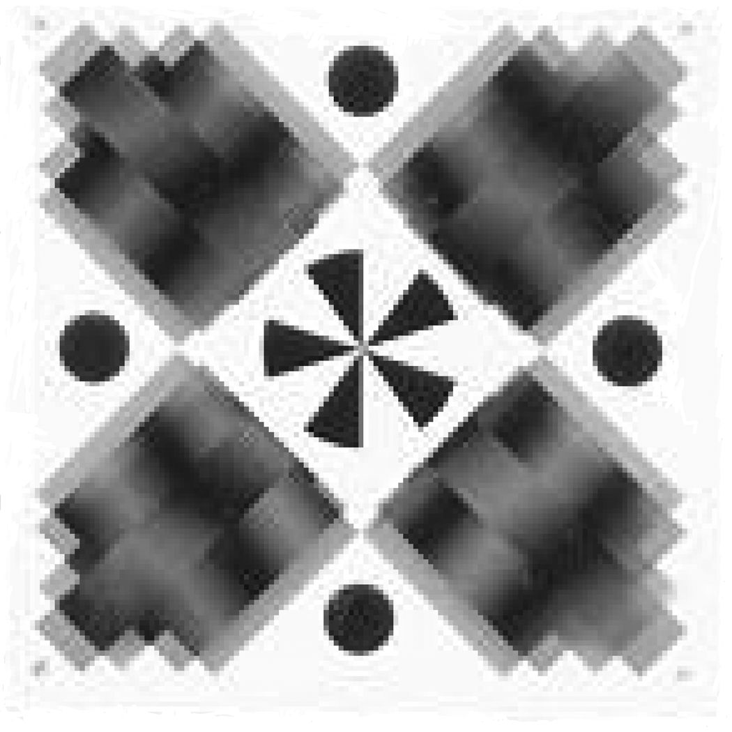
RGR target. Moiré patterns co-vary with out-of-plane rotations, permitting 6-DOF tracking with a single camera system.
Methods
Nine individuals (25.6±5.0years, 78.2±15.8kg, 1.75±0.07m) volunteered to participate in this study. An informed consent form was read and signed by all volunteers prior to the beginning of the study. The protocol was approved by the university Institutional Review Board. Volunteers were accepted in the study if they had not suffered a knee injury requiring surgery and have been free of any other injury within the previous six months that could interfere with normal movements.
Prior to data collection, the multi-camera and RGR coordinate systems were co-registered using a sequence of 30 static poses of a four marker plate with an RGR target rigidly attached. The static poses were captured over a range of 270°, 120°, 120° for pitch, roll, and yaw respectively; and 0.6, 0.6, and 1.2m in the X, Y, and Z directions respectively. An optimization scheme was then used to find the transformation between the coordinate systems. The RMS errors between RGR-target and multi-camera pose information were 0.57°, 0.68°, and 0.79° for pitch, roll, and yaw respectively. The spatial RMS errors were 3.4, 1.9, and 1.0mm respectively for the X, Y, and Z directions.
In order to track knee kinematics, plates with four reflective spheres were attached to the thigh and shank with elastic Velcro straps, and an RGR target was mounted to the center of each plate (Figure 2). Subjects wore standard laboratory footwear (Saucony Jazz, Lexington, MA). Marker and RGR target trajectories were collected simultaneously at 100Hz with a seven-camera Motion Analysis Eagle System (Santa Rosa, CA, USA), and a Basler A501k (Ahrensburg, Germany) 1.3 megapixel (Mp) camera located 3.5m from the center of the capture volume. Ground reaction force (GRF) data were collected synchronously at 500Hz to determine the floor contact phase with an AMTI OR6-5 force platform (Watertown, MA, USA).
Figure 2.

Sagittal plane camera image of the thigh and shank retro-reflective marker plates with an RGR target mounted in the center.
After attaching the plates, a two-second standing calibration trial was collected. Each subject then completed three single-leg land-and-cut maneuvers, initiated from a 35cm raised platform placed approximately 10cm behind the back edge of the force platform. During each landing task, subjects were encouraged to land with their right foot on the center of the force platform. Unsuccessful landings because of loss of balance, or touching the floor with the contralateral limb (prior to the cutting maneuver) were immediately repeated.
The raw 3D kinematic data were filtered using a fourth-order, zero lag, recursive Butterworth filter with a cutoff frequency of 12 Hz. 6-DOF pose of the thigh and shank were calculated for the Eagle-based measurements using a standard cross product approach (Areblad et al., 1990). Segment poses were also calculated based on the information intrinsic to the RGR target moiré patterns (Armstrong et al., 2002). The methodology behind interpreting moiré patterns generated by the RGR targets is elaborated on by Armstrong et al. (2002). Three-dimensional knee angles were calculated using a joint coordinate system approach (Grood & Suntay, 1983), and all joint angles were reported relative to the neutral calibration position. Processed data were time normalized to 101 data points. To assess the relationship between the two measurement systems, the coefficient of determination (R2) and root mean square (RMS) error between the time series were calculated to depict the similarity of the two systems. Additionally, touchdown (TD) and peak angles of the knee were reported in all three planes and compared using a paired t-test (p<0.05).
Results
The time series of the thigh and shank segment angles, and knee joint angles in the sagittal, frontal, and transverse planes matched closely (Figure 3). Most of the R2 values between the two measurement systems for the two plates were >0.9 (Table 1). The RMS errors for the thigh and shank angular degrees of freedom were 2–3 degrees. The spatial measurement RMS errors were ~1 cm in the vertical and anterior-posterior directions, while the mediolateral differences were 1.5–2 cm. This direction represents the depth axis of the single camera and is the degree of freedom with the greatest uncertainty for the RGR system. There were no statistical differences in the discrete knee kinematic variables between the Eagle and RGR measurements in any plane (Table 2). The only discrepancies appeared in the frontal plane, where there was trend suggesting a difference in peak angles and only a moderate correlation in touchdown angles.
Figure 3.

Mean thigh, shank, and knee angle curves during the ground contact phase for the Eagle system (solid black line) and RGR system (solid gray line).
Table 1.
Mean R2 and RMS values for the thigh and shank targets, and knee joint angles. Pitch, roll, and yaw equate to the sagittal, frontal, and transverse planes of the subject. The spatial variables X, Y, and Z, are the corresponding axes.
| R2 | RMS | ||
|---|---|---|---|
| Shank | |||
| Pitch (deg) | 0.995 (0.004) | 2.38 (1.50) | |
| Roll (deg) | 0.804 (0.141) | 3.04 (1.34) | |
| Yaw (deg) | 0.902 (0.129) | 2.77 (1.05) | |
| X(mm) | 0.863 (0.143) | 14.9 (4.9) | |
| Y(mm) | 0.986 (0.012) | 8.0 (1.9) | |
| Z (mm) | 0.990 (0.010) | 11.8 (3.2) | |
| Thigh | |||
| Pitch (deg) | 0.997 (0.003) | 2.74 (1.47) | |
| Roll (deg) | 0.906 (0.131) | 2.17 (1.33) | |
| Yaw (deg) | 0.967 (0.025) | 2.67 (0.65) | |
| X(mm) | 0.966 (0.032) | 21.8 (16.5) | |
| Y(mm) | 0.998 (0.001) | 10.8 (4.4) | |
| Z (mm) | 0.978 (0.000) | 10.8 (6.9) | |
| Knee | |||
| Flexion (deg) | 0.998 (0.001) | 1.65 (0.60) | |
| Adduction (deg) | 0.845 (0.159) | 2.42 (1.42) | |
| Int. Rotation (deg) | 0.839 (0.146) | 2.19 (1.68) | |
Table 2.
Comparison of knee joint touchdown and peak angles collected with the Eagle and RGR systems in all three planes.
| Sagittal | Frontal | Transverse | ||||
|---|---|---|---|---|---|---|
| TD | Peak | TD | Peak | TD | Peak | |
| Eagle | −13.8(7.6) | −68.4(13.6) | 1.9(2.1) | −6.8(6.9) | −2.6(4.9) | 7.7(4.7) |
| RGR | −14.0(7.6) | −68.9(13.8) | 1.4(2.8) | −5.6(7.7) | −2.7(5.9) | 8.6(5.8) |
| Difference | 0.2 | 0.5 | 0.5 | −1.2 | 0.1 | −0.9 |
| p-value | 0.823 | 0.191 | 0.477 | 0.107 | 0.881 | 0.204 |
| R2 | 0.97 | 0.99 | 0.57 | 0.97 | 0.94 | 0.95 |
Discussion
The purpose of this study was to compare motion data for standard athletic movements recorded simultaneously with the RGR system and a multi-camera system. Previous studies have shown that orientation and position information recorded by the RGR system has high measurement precision (Armstrong et al., 2002) and is strongly correlated with a traditional multi-camera system across a series of static poses (O'Connor et al., 2007). The results of this study demonstrate the ability of the RGR system to record moving pose information from multiple RGR targets at a sampling rate adequate for assessment of human movement and strongly support the ability to use the RGR technology as a valid 3D motion capture system.
The frontal plane kinematic patterns in the current study differ somewhat from previous work (O'Connor et al., 2009), which is likely a product of the definition of the segment coordinate systems. A secondary purpose of this study was to utilize an experimental protocol that can be quickly and easily implemented for kinematic field testing. As such, segment local coordinate systems were not defined based on anatomical landmarks. All kinematics were reported relative to the standing condition, which assumed that the thigh and shank local coordinate systems were aligned with the global coordinate system for the standing trial. This assumption is certainly violated to some degree, leading to misorientation of the knee axes (Blankevoort et al., 1988; Piazza & Cavanagh, 2000; Ramakrishnan & Kadaba, 1991). While sagittal plane angle are minimally affected by this misalignment, the effects are dramatic in the frontal and transverse planes (Blankevoort et al., 1988; Ramakrishnan & Kadaba, 1991; Woltring, 1994). To maintain the relative ease and speed of data collection in the field, further work is ongoing to adapt methods for correcting potential knee axis misalignment that are currently employed for purposes of quantitative gait analysis (Rivest, 2005; Schache et al., 2006). It should be noted that this issue existed for both systems and did not affect reported comparisons.
The RGR system has unique requirements for human motion capture. The RGR target moiré patterns require a visible footprint of 60×60 pixels (Armstrong et al., 2002). Capture volume is then determined based on the size of the RGR target, resolution of the camera, and focal length of the lens. In the current study, a 1.3Mp camera and 65×65mm targets were used, resulting in a capture volume of approximately 1.0×1.0×1.5m in the X (M-L), Y (A-P), and Z (vertical) directions respectively. One of the next steps is to implement a 4.5Mp camera that will allow for a larger capture volume, smaller targets, or some combination of the two. Additionally, we are currently working to incorporate automated event detection to increase the effectiveness of the RGR system as a stand-alone mobile measurement system.
While numerous clinical questions can be addressed with RGR technology, the development of the RGR technology for human motion capture has focused on ACL injury screening. Quantifying an individual’s movement patterns during athletic maneuvers through 3D motion analysis has been shown to have the greatest promise in identifying those at increased risk of ACL injuries (Hewett et al., 2005). Early identification of these individuals will allow for targeted prevention strategies that can substantially reduce this risk (Hewett et al., 2006). Motion analysis as a clinical diagnostic tool must have adequate selectivity and sensitivity to inform clinical decisions, both developing and validating protocols will require prospectively tracking far greater numbers of individuals than have been studied to date. Reaching a large pool of study subjects, as well as eventual clinical deployment of motion analysis, will require a diagnostic tool that can be distributed to multiple clinical environments, to facilitate collection of much larger subject pools than can be currently accomplished by bringing athletes to specialized laboratories. The RGR technology, with the unique ability to track 3D motion through the use of a single camera, is such a system. It is our belief that RGR motion capture technology offers the promise of expanding the applicability of human movement capture while maintaining an accurate description of the individuals’ movement pattern.
Acknowlegments
The authors would like to thank the UWM Research Growth Initiative and the NIH (1R15AR056117-01) for their financial support of this project.
Footnotes
Conflict of Interest Statement
Weinhandl, O'Connor and Barrows have no personal or commercial relationships related to this work that would lead to a conflict of interest. Armstrong and Kusik are the principles of Metria Innovation, a startup company engaged in commercializing Retro-Grate technology.
References
- Areblad M, Nigg BM, Ekstrand J, Olsson KO, Ekstrom H. Three-dimensional measurement of rearfoot motion during running. Journal of Biomechanics. 1990;23(9):933–940. doi: 10.1016/0021-9290(90)90358-a. [DOI] [PubMed] [Google Scholar]
- Armstrong BSR, Andrews-Shigaki B, Barrows RT, Kusik P, Ernst T, Speck O. Performance of stereo vision and retro-grate reflector motion tracking systems in the space constraints of an MR scanner. In Proceedings of the ISMRM 17th Scientific Meeting and Exhibition; Honolulu, HI. 2009. p. 5474. [Google Scholar]
- Armstrong BSR, Verron T, Heppe L, Schmidt K. RGR-3D: Simple, Cheap detection of 6-DOF Pose for Tele-Operation, and Robot Programming and Calibration. In Proceedings of the IEEE International Conference on Robotics & Automation; Washington, D.C.. 2002. pp. 2938–2943. [Google Scholar]
- Blankevoort L, Huiskes R, de Lange A. The envelope of passive knee joint motion. Journal of Biomechanics. 1988;21(9):705–720. doi: 10.1016/0021-9290(88)90280-1. [DOI] [PubMed] [Google Scholar]
- Grood ES, Suntay WJ. A joint coordinate system for the clinical description of three-dimensional motions: application to the knee. J Biomech Eng. 1983;105(2):136–144. doi: 10.1115/1.3138397. [DOI] [PubMed] [Google Scholar]
- Hewett TE, Ford KR, Myer GD. Anterior cruciate ligament injuries in female athletes: Part 2, a meta-analysis of neuromuscular interventions aimed at injury prevention. The American Journal of Sports Medicine. 2006;34(3):490–498. doi: 10.1177/0363546505282619. [DOI] [PubMed] [Google Scholar]
- Hewett TE, Myer GD, Ford KR, Heidt RS, Jr, Colosimo AJ, McLean SG, van den Bogert AJ, Paterno MV, Succop P. Biomechanical measures of neuromuscular control and valgus loading of the knee predict anterior cruciate ligament injury risk in female athletes: a prospective study. The American Journal of Sports Medicine. 2005;33(4):492–501. doi: 10.1177/0363546504269591. [DOI] [PubMed] [Google Scholar]
- Kawamura CM, de Morais Filho MC, Barreto MM, de Paula Asa SK, Juliano Y, Novo NF. Comparison between visual and three-dimensional gait analysis in patients with spastic diplegic cerebral palsy. Gait & Posture. 2007;25(1):18–24. doi: 10.1016/j.gaitpost.2005.12.005. [DOI] [PubMed] [Google Scholar]
- O'Connor KM, Armstrong BSR, Watts SR, Farrah MMA, Bottum MC. An innovaative diagnostic tool for reducing traumatic knee injuries. In Proceedings of the 31st Annual Meeting of the American Society of Biomechanics; Palo Alto, CA. 2007. [Google Scholar]
- O'Connor KM, Monteiro SK, Hoelker IA. Comparison of selected lateral cutting activities used to assess ACL injury risk. Journal of Applied Biomechanics. 2009;25(1):9–21. doi: 10.1123/jab.25.1.9. [DOI] [PubMed] [Google Scholar]
- Piazza SJ, Cavanagh PR. Measurement of the screw-home motion of the knee is sensitive to errors in axis alignment. Journal of Biomechanics. 2000;33(8):1029–1034. doi: 10.1016/s0021-9290(00)00056-7. [DOI] [PubMed] [Google Scholar]
- Ramakrishnan HK, Kadaba MP. On the estimation of joint kinematics during gait. Journal of Biomechanics. 1991;24(10):969–977. doi: 10.1016/0021-9290(91)90175-m. [DOI] [PubMed] [Google Scholar]
- Rivest LP. A correction for axis misalignment in the joint angle curves representing knee movement in gait analysis. Journal of Biomechanics. 2005;38(8):1604–1611. doi: 10.1016/j.jbiomech.2004.07.031. [DOI] [PubMed] [Google Scholar]
- Schache AG, Baker R, Lamoreux LW. Defining the knee joint flexion-extension axis for purposes of quantitative gait analysis: an evaluation of methods. Gait & Posture. 2006;24(1):100–109. doi: 10.1016/j.gaitpost.2005.08.002. [DOI] [PubMed] [Google Scholar]
- Woltring HJ. 3-D attitude representation of human joints: a standardization proposal. Journal of Biomechanics. 1994;27(12):1399–1414. doi: 10.1016/0021-9290(94)90191-0. [DOI] [PubMed] [Google Scholar]