Abstract
In this paper, we have fabricated and tested several composite materials with a mesh matrix, which are used as encapsulation materials for a novel implantable movable-microelectrode microelectromechanical-system (MEMS) device. Since movable microelectrodes extend off the edge of the MEMS chip and penetrate the brain, a hermetically sealed encapsulation was not feasible. An encapsulation material is needed to prevent cerebral-spinal-fluid entry that could cause failure of the MEMS device and, at the same time, allow for penetration by the microelectrodes. Testing of potential encapsulation materials included penetration-force measurements, gross-leak testing, maximum-pressure testing, and biocompatibility testing. Penetration-force tests showed that untreated mesh matrices and silicone-gel-mesh composites required the least amount of force to penetrate for both nylon 6,6 and polypropylene meshes. The silicone-gel-, poly(dimethylsiloxane)-, polyimide-, and fluoroacrylate-mesh composites with the nylon-mesh matrix were all able to withstand pressures above the normal intracranial pressures. Fourier-transform infrared-spectroscopy analysis and visual inspection of the implanted devices encapsulated by the silicone-gel-mesh composite showed that there was no fluid or debris entry at two and four weeks postimplantation. We conclude that a composite of nylon and silicone-gel meshes will meet the needs of the new generation of implantable devices that require nonhermetic encapsulation.
Index Terms: Bio-microelectromechanical systems (MEMS), composite, neural implant, neural prostheses, packaging, reliability
I. Introduction
Packaging and reliability of microelectromechanical systems (MEMS) are among the most challenging problems of designing a device. Typical requirements for MEMS packaging include hermetic sealing, vertical feedthroughs, thermal management, mechanical support, and RF transparency. In addition, many MEMS devices operate in harsh environments that involve vibrations, extreme temperatures, and corrosive fluids. This is particularly true in MEMS devices being designed and developed for implantable applications. Implantable devices need to be biocompatible and durable and to operate in harsh fluidic environments that contain salts (NaCl and KCl), various proteins, enzymes, and blood [1]. The packaging material therefore needs to be biocompatible in order to prevent any adverse tissue reaction to the host.
Brain prosthesis is an exciting emerging application for which MEMS-based microelectrodes and microelectrode arrays are designed to operate as implantable devices; however, the devices are usually fixed to the skull, while the microelectrodes penetrate the brain via a craniotomy. In most cases, the dura mater (the upper meningeal layer) is removed or incised after a craniotomy to enable penetration of microelectrodes into the brain, which allows cerebral spinal fluid (CSF) to fill the craniotomy and perhaps even enter the device if the device is inadequately encapsulated. Current implantable microelectrode arrays are nonmovable and consist of one or more recording sites on a single shank or multiple shanks, and an interconnect cable [2]–[7]. There are several stationary microelectrode devices that integrate advanced complex circuitry for performing wireless signal readouts or amplification of the neural signal [8]. These types of devices often use glass anodic bonding to seal the electrical components from damage. Blood or CSF entry is sometimes prevented by using an artificial dural sealant that encapsulates the craniotomy and prevents leakage [9]. However, all of the aforementioned devices involve stationary microelectrodes, which can use hard polymer encapsulation materials to prevent fluid entry. Hard encapsulation materials are not feasible as dural sealants in the case of movable microelectrodes because the encapsulation material would adhere to the microelectrodes and prevent them from moving.
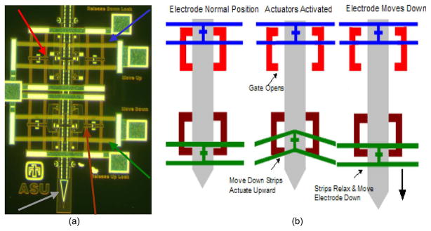
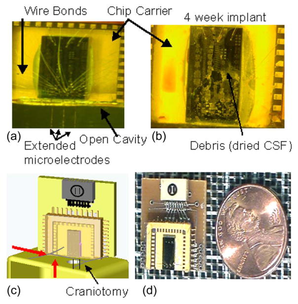
Microelectrodes that move after implantation are increasingly seen as a viable approach to track or seek single neuronal signals or maintain a high signal-to-noise ratio in single neuronal recordings over a long duration. There have been numerous attempts at fabricating implantable movable microelectrodes using piezoelectric actuators [10], [11], hydraulics [12], and manually operated screws and gears [12]–[14]. The aforesaid devices, however, use large motors or robust mechanical techniques, which are less susceptible to fail due to fluid entry to move the microelectrodes. However, recently, we developed novel movable microelectrodes that use V-beam thermal actuators to move the microelectrodes in the brain postimplantation [15]–[17]. The MEMS devices are fabricated using the SUMMiT-V process at Sandia National Laboratories. The device consists of five layers of phosphorus-doped polysilicon for the microelectrodes and microactuators. Each microelectrode is associated with four actuators, two of which are lock mechanisms to prevent unwanted movement, and the other two are used to move the microelectrode bidirectionally. A micrograph and a schematic of how our devices function are shown in Fig. 1. The entry of surgical debris, CSF, or exudates from the skin incision or blood is one of the primary failure modes of these devices, as shown in Fig. 2(a) and (b). Fluid entry can occur via two methods: 1) by filling the craniotomy where the device sits on the skull, and as fluid continues to rise, the capillary force will allow fluid to enter the device or 2) the fluid from the outside tissue or on top of the skull can flow into the cavity opening on the device [Fig. 2(c)]. The implantable array of microactuated microelectrodes cannot be hermetically sealed because the microelectrodes extend off the edge of the chip and require movement postpackaging and postimplantation. Fluid entry into this chip results in short-circuiting of the leads connecting the recording sites of the implant. In addition, the residues left behind by the fluid after drying often create extensive mechanical barriers for the moving parts on the chip. The device is wire bonded to a sawed-off chip carrier that is then bonded to a custom-made printed circuit board (PCB) using surface-mount technologies. A glass cover is bonded to the chip carrier to help prevent entry of any debris or failure due to the animal hitting the device. The sawed-off chip carrier is needed to allow the microelectrodes to extend off the edge of the chip. However, this also creates an open cavity that allows any fluid to enter the chip via the methods shown in Fig. 2(c). A more detailed description of our packaged device has previously been reported [18].
Fig. 1.
(a) Micrograph of the V-beam electrothermal actuators and microelectrodes. The colored arrows show the four actuators and the microelectrode (gray—microelectrode, green—move-down actuator, blue—move-up actuator, red—release-down actuator, and brown—release-up actuator. (b) Schematic of how the actuators function in order to move the microelectrode.
Fig. 2.
Micrographs of our bio-MEMS device. (a) Clean device before implantation, with three movable microelectrodes extending off the edge of the chip. The chip is 3 mm by 6 mm, and it is wire bonded to a chip carrier with a glass-cap package. (b) Micrograph of a device that was implanted for a period of four weeks without any protective layer. Fluid entry and the debris left behind after dehydration are clearly evident, which prevented movement of the microelectrodes. (c) Schematic of the implanted device resting on the skull, with the microelectrodes extending through the craniotomy. The red arrows show fluid entry either via the craniotomy or the exudates from the skin incision surrounding the craniotomy. (d) Micrograph of a packaged device next to a U.S. penny.
Another approach to prevent fluid entry into the device is to seal the craniotomy with a soft hydrophobic gel as a dural sealant that is penetrable by the microelectrodes [19]. The gel is placed inside the craniotomy and helps to prevent fluid entry via the craniotomy opening. However, applying an extremely thin layer of sealant over the craniotomy was difficult to repeat besides being ineffective against exudates from the surrounding skin that are outside the sealant (second source of fluid entry). In this paper, we tested several candidate mesh-composite materials that can be used to encapsulate the MEMS device in order to prevent fluid or debris entry in long-term implantation experiments. Encapsulating the device or open cavity of the chip carrier allows us to prevent debris or fluid entry in both the craniotomy and the surrounding skin. A mesh material is required because the material needs to have pores to allow our microelectrodes to penetrate through the pores. The mesh material acts as the matrix in the composite materials and allows us to consistently obtain a thin layer so that our microelectrodes can penetrate through the composite with more ease. In this paper, we used two different mesh-matrix materials that were commercially available and created composite materials using standard benchtop fabrication techniques. The composite materials were selected for testing because of their hydrophobic nature, their prior use in packaging applications, and their capability of forming thin layers that can easily be penetrated by our microelectrodes. Each of the composite materials was tested for leaks using standard gross-leak testing, for cytotoxicity, for their ability to withstand physiologically relevant pressure conditions, and for their ability to allow penetration of thin microelectrodes. Penetration-force testing was extremely important with implantable movable microelectrodes since the microelectrodes are needed to penetrate the encapsulation material without buckling. This paper assessed several mesh-matrix composite materials for encapsulating a MEMS-based movable microelectrode device that can easily be penetrated by the microelectrodes while still protecting the actuators or circuits from being damaged due to fluid or debris entry.
II. Fabrication of the Encapsulation
In order to prevent fluid entry, an encapsulation material must be used to seal the open cavity of the sawed-off chip carrier. The material for encapsulation needed to be (a) bio-compatible, (b) hydrophobic, (c) spun into thin films that can be penetrated by microelectrodes and are able to retain their dimensional integrity and sealing capabilities after penetration by microelectrodes (low surface energy in the thin films), and (d) be able to withstand the intracranial pressure (ICP) exerted by the brain tissue. The nonhermetic encapsulation needs to prevent CSF and blood from entering the chip. Prior experience with soft hydrophobic gels demonstrated several deficiencies such as lack of integrity in the films after penetration if the films were thin and inability of the microelectrodes to penetrate the films if the films were too thick. Therefore, we chose a hydrophobic mesh-matrix encapsulation that would allow the microelectrodes to penetrate through its pores. The mesh-matrix material needs to seal the open cavity to prevent fluid entry but still be soft enough to allow the microelectrodes to penetrate and move with ease postimplantation. However, the untreated mesh-matrix materials were unable to withstand normal physiological ICPs, thus allowing CSF and blood to enter the chip. In order to meet all the needs outlined earlier, different composites of the mesh matrix and other hydrophobic sealants were made and tested for their ability to encapsulate the MEMS device. The pores in the mesh matrix are necessary to allow the microelectrodes to penetrate through the composite material with more ease. The matrix is used as a support structure to allow us to produce thin films of various materials.
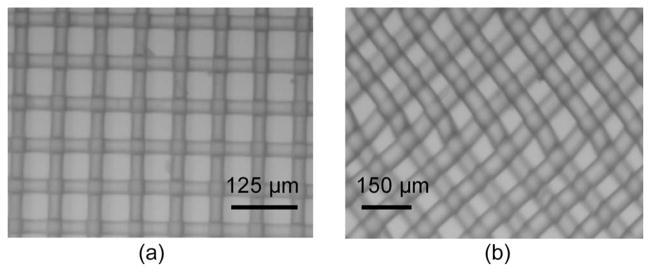
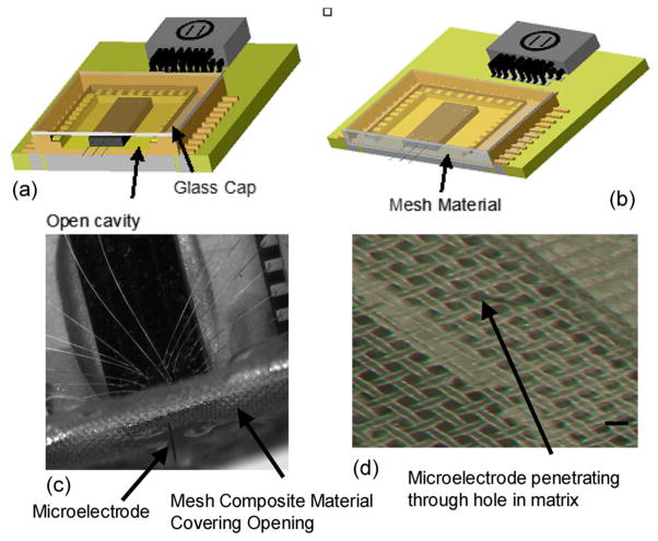
Preliminary penetration testing (data not shown) of various commercially available mesh-matrix materials for the forces required for penetration by microelectrodes showed that there were two good candidate mesh materials: (a) nylon 6, 6 with 60-μm pore opening [Fig. 3(a)] and polypropylene with 75-μm pore opening [Fig. 3(b)] (both from Small Parts, Inc.). The mesh pore sizes were chosen based on the size of the microelectrodes (rectangular cross section of 50 × 5 μm approximately) on the MEMS device. The microactuated microelectrode devices were fabricated using the SUMMiT-V process at Sandia National Laboratories, Albuquerque, NM. The fabrication and features of our device have been previously described in detail [15]. A schematic of an unpackaged device with an open cavity is shown in Fig. 4(a). The composite mesh material is bonded to the glass and the chip carrier to seal the open cavity Fig. 4(b). The microelectrodes penetrate through the composite mesh material at the pore location, as shown in Fig. 4(c) and (d). Our devices do not require a tight seal around the microelectrodes in order to function. The encapsulation needs to be able to hold back large amounts of fluids (approximately a few microliters). A tight seal would, in fact, make the microelectrodes difficult to move since the microactuators are only capable of producing several hundred micronewtons of force.
Fig. 3.
Micrographs of the two mesh-matrix materials. (a) Nylon-mesh matrix with 60-μm holes. (b) Polypropylene-mesh matrix with 75-μm holes.
Fig. 4.
Schematic illustrations of the packaged MEMS devices. (a) Packaged MEMS device with a glass-cap package and an open cavity. The chip carrier is sawed off to allow the microelectrodes to penetrate the brain. However, an open cavity is created where fluid can enter from the craniotomy opening. (b) Proposed encapsulation packaging where the mesh composite material is bonded to the open cavity, thus preventing fluid entry. (c) Micrograph of a packaged device, with the extended microelectrode penetrating through the silicone-gel-mesh composite material. The composite material encapsulates the open cavity in the chip carrier and prevents fluid entry. (d) Micrograph of the silicone-gel-mesh composite material, with the microelectrode penetrating through the silicone gel at the hole location of the mesh matrix. The scale bar is 60 μm.
A. Silicone-Gel Composite
The silicone gel (3-4680, Dow Corning, Midland, MI) that was selected as a possible composite candidate had resealable capabilities and was typically used in preventing moisture or fluid entry in prototyped IC chips. The silicone gel was widely used as an encapsulation material in applications where the chip needed to be probed periodically after it was packaged. The silicone gel was recently demonstrated to be a good candidate as an artificial dural sealant [19]. The gel was hydrophobic, soft, semitransparent, biocompatible, and cured in 10–15 min at room temperature, which made it an ideal candidate for testing as a composite material for preventing fluid entry in a bioimplantable device. The silicone gel, by itself, was prone to tearing at gel thicknesses that would allow penetration by microelectrodes and was therefore not feasible as an encapsulation material. However, the mesh matrix acts as a support structure for the silicone gel, allowing the silicone gel to be thin without tearing.
In order to fabricate the silicone-gel mesh-composite material, small pieces of the mesh-matrix materials were cut and placed on a glass cylinder. The silicone gel was mixed at a volume ratio of 1 : 1, and a small drop was placed in the center of the mesh matrix. Using an approach similar to screen printing, the sharp edge of a blade was used to uniformly spread out the gel across the mesh matrix in order to form a thin layer before the gel was allowed to cure. The nylon-and polypropylene-mesh-matrix materials had thicknesses of approximately 30 and 50 μm, respectively. The silicone gel percolated through the openings of the mesh and created a thin layer of silicone gel on both sides with a total approximate thickness of 100 μm.
B. Fluoroacrylate Composite
A fluoroacrylate material (EGC-1700, 3M) was chosen because of its low surface energy (11 dyn/cm), ability to form a thin layer (~1 μm), and its ease of fabrication. The fluoroacrylate material has been used previously as an antistiction material in MEMS packaging. The two mesh-matrix materials were cut into small pieces, dip coated into the fluoroacrylate material, and allowed to air dry. The material dried within minutes of being dip coated. This method did not form a thin layer covering the pores, but instead, the fluoroacrylate lowered the surface energy, thus making fluid entry more difficult.
C. PDMS Composite
Poly(dimethylsiloxane) (PDMS) was chosen as a potential composite material because of its wide use in packaging and implantable devices. PDMS is a hydrophobic, biocompatible, and semisoft material that can be spun into thin conformal layers with well-established fabrication techniques. PDMS is widely used in bioimplantable devices, including in the brain [20], [21]. The PDMS composite material was prepared by mixing the prepolymer and curing agent (Sylgard 184, Dow Corning) at a 10 : 1 weight ratio and degassed to remove air bubbles from the mixture. While in its liquid precursor state, PDMS was spun on the mesh-matrix materials at a spin rate of 5000 r/min for 20 s. The PDMS composite material was cured at 65 °C for 4 h. The thickness of the PDMS and matrix was approximately 75 μm.
D. Thinned Polyimide Composite
Polyimide (PI 2611, HD Microsystems) was chosen to be a candidate for a composite material because of its wide use in packaging [22], [23] and in implantable devices [24], [25]. Polyimide is hydrophobic and biocompatible and can be spun to a thin layer. Typically, PI 2611 can be spun down to a couple of micrometers; however, Feili et al. developed a method to thin the polyimide [26]. To achieve a lower viscosity resin and reduce the final thickness of the polyimide, it was first mixed in a 1 : 1 volume percentage with NMP (1-methyl 2-pyrrolidone, Sigma–Aldrich). The thinned polyimide resin was poured into the center of the mesh-matrix materials and spun at 5000 r/min for 30 s. Typically, PI-2611 polyimide needs to be cured at 350 °C to be completely imidized; however, nylon has a melting temperature of around 255 °C, and polypropylene has a melting temperature of approximately 160 °C. To prevent the matrix from melting, the polyimides were only intermediately baked at 150 °C and 225 °C for 2 h for polypropylene and nylon, respectively. The polyimide was not completely imidized in our process, but the film was cured to form a softer material with more pinhole defects, which met our needs, since we want a material that will prevent fluid entry but is easy to penetrate. The defects and pin-sized holes of the softer polyimide should allow for easier penetration than a fully imidized layer of polyimide. The thickness of the polyimide layer was approximately 700 nm compared to 2–3 μm if the resin was not thinned. The thickness was measured using a reflective spectroscopy (F40, Filmetrics, Inc.). Since the polyimide is not completely imidized, the biocompatibility of PI-2611 could be altered. However the biocompatibility of polyimide that has not been completely imidized has been shown previously [27]. In this paper, they showed that cells adhered more to the fully cured polyimide (PI 2611); however, the lower cured polyimide was still found to be nontoxic.
E. Photoresist Composite
A positive photoresist (AZ3312, AZ Electronics Material) was used because it was widely available and can be spun into thin layers. The mesh-matrix material was taped down to a silicon wafer. Then, 1 mL of photoresist was placed directly in the center of the mesh, and the spinner was slowly accelerated to 6000 r/min. The mesh material was then soft baked at 80 °C for 10 min, and then, it was allowed to hard bake at 120 °C for an additional 20 min. Most of the photoresist fell through the pores; however, the threads were coated with photoresist. The thickness of the spun photoresist was approximately 900 nm, which was measured based on reflective spectroscopy.
The contact angles of all the composite materials were tested, and the results are shown in Table I. Contact measurements were measured using a goniometer, where 5 μL of deionized water was placed at the center of the composite materials.
TABLE I.
Summary of the Mean Contact Angles of the Different Mesh Composite Materials Tested
| Composite | Contact Angles (mean ± std. Deviation) | |
|---|---|---|
| Nylon | Polypropylene | |
| Control | 93.8 ±9.9 | 106.6 ± 10.1 |
| Silicone Gel | 108.2 ± 5.3 | 102.2 ± 4.8 |
| Fluoroacrylate | 125.9 ± 11.6 | 130.1 ± 6.9 |
| PDMS | 105.6 ± 3.3 | 102.6 ± 7.2 |
| Polyimide | 117.7 ± 7.7 | 118.7 ± 4.9 |
| Photoresist | 107.2 ± 3.9 | 106.9 ± 0.9 |
III. Testing Methods
A. Penetration-Force Measurements
Penetration-force-measurement tests were performed on various mesh-matrix materials using a high-precision load cell (MTC 10/30 ZER, Wipotec, Germany) with a resolution of 0.1 mg and a 16-b A/D converter. The load cell was placed on a vibration-free table in order to prevent any unwanted mechanical noise. Glass cylinders (n = 3) were bonded on a glass coverslip and adhered to the load cell using a double-sided carbon tape in order to prevent movement. The mesh-matrix materials were bonded to the glass cylinder.
To study the penetration force, a single-shank silicon microelectrode (made by the University of Michigan, Ann Arbor, popularly called the “Michigan microelectrode”) that was 60 μm wide, 15 μm thick, and 3 mm long was epoxy bonded to a PCB. The microelectrode was bonded to the PCB that, in turn, was secured to a motorized microdrive (FHC, Inc.) for mesh penetration. The electrode was moved down at a rate of 10 μm/s until the microelectrode either penetrated the mesh or buckled without penetrating. The maximum force measured during penetration was repeated three or four times for each sample, and each mesh composite had three (n = 3) samples. If the microelectrode buckled, the force measurement was discarded.
B. Gross-Leak Testing
Gross-leak testing was performed in order to determine which composite would give sufficient protection over chronic conditions (more than two weeks) from fluid entry for an implanted device. The aim was to test the material for degradation in material integrity over time at normal ICP. A custom-made testing setup was created by drilling 3-mm holes into a polystyrene substrate. The samples of each (n = 12) of the various mesh composites were carefully epoxy bonded to the substrate in order to cover the hole. A single 50-μm stainless-steel wire penetrated each of the mesh materials in order to simulate a real implantable device where the mesh composite will be penetrated by a microelectrode of similar dimensions. In order to validate that the circular cross section of the stainless-steel wire did not increase the sealing capabilities compared to a rectangular cross-sectional microelectrode, we penetrated a silicone-gel mesh-composite material with a “Michigan microelectrode” with a rectangular cross section.
Leak tests were conducted by immersing the sealed wells into 2.5 in of DI water, giving an average pressure of 6.35-cm H2O (normal ICP). Similar leak tests have been performed by immersing the devices in isopropyl alcohol (IPA) [28], [29]. IPA was used in those earlier experiments because of its ability to penetrate more easily than DI water and hence help in identifying even tiny leaks. DI water was used in our paper because of its ability to penetrate more easily than blood or CSF. The stainless-steel wires and “Michigan probe” were moved approximately 500 μm every day in order to simulate a working environment. The wells were immersed for 504 h, and the survival rate was measured. Food coloring was added to the DI water in order to help predict if a leak had occurred. This method was able to detect leakage of < 1 μL. Our devices require at least 5 μL of leakage to cause failure due to the volume of space within the chip carrier. The survival rate is based on the number of devices that showed more than a 1-μL leak during the duration of the experiment.
C. Pressure Testing
After implantation, the mesh composites must be able to withstand ICPs ranging from 5 cm of H2O in rats [30] to 6.5–18 cm of H2O in humans [31], [32]. A custom-made U-tube-based manometer was made to test the maximum pressure that the mesh composites could withstand. Twelve samples of each mesh composite were tested, and colored DI water was added slowly (up to a maximum of 35-cm H2O) until a leak was observed. A leak was observed once more than 1 μL of fluid penetrated the material. Once the pressure measured 35-cm H2O, the tests were stopped since it was more than double the normal ICP observed in humans and almost seven times the typical pressures observed in a rat.
D. Cytotoxicity Testing
Cytotoxicity tests were conducted for all the different mesh-composite materials. Experiments were performed in order to test the cell viability of the various mesh composites according to ISO 10993-5 standards. The samples of the mesh composites were placed in separate standard polystyrene wells and were UV sterilized. Polystyrene wells acted as the control. Neuroblastoma cells (N2a) were cultured in Eagle’s minimum essential medium on two samples of each mesh composite. The N2a cells were then added on top of the mesh composites. The cells were then placed back in an incubator at 37 °C with 5% CO2. After three days, the cells were examined using a light-field microscope, after which a live–dead-cell assay was performed (Molecular Probes, Eugene, OR), consisting of 2-μM calcein AM, and 4-μM ethidium homodimer-I in 200-μl PBS was added to the well. Fluorescent imaging was performed using a fluorescent stereomicroscope. The live–dead-cell assay contains the chemicals calcein AM that stains the living cells green under fluorescence and ethidium homodimer that stains the dead cells red. The N2a cells are a cancerous neuronal cell line, which has a higher sensitivity to toxic materials compared to commonly tested L929 mouse fibroblasts. The cytotoxicity test performed here is in accordance with ISO 10993-5 standards.
E. In Vivo Testing
In order to determine if the mesh-composite encapsulation protected the devices from fluid or debris entry, we implanted dummy silicon microchips (of similar dimensions as the microactuated microelectrode chips) with microelectrodes and encapsulated the devices by mesh composites composed of silicone gel with a nylon mesh matrix in (n = 3) Sprague–Dawley rats (250 g). In another cohort of rats (n = 3), the devices with untreated nylon-mesh materials with no gel were used as encapsulation and were implanted. The silicone-gel-mesh composite was selected for the encapsulation based on the results of the previous bench-top tests. The bench-top tests were used to determine which of the mesh materials had the highest likelihood of success as an in vivo encapsulation material. The results of the bench-top tests (Table II) show that the silicone gel with a nylon matrix had the highest probability of success, so it was selected to be tested in vivo.
TABLE II.
Ranking of the Different Nylon-Mesh Composite Materials
| Control | Silicone Gel | Fluoroacrylate | PDMS | Polyimide | Photoresist | |
|---|---|---|---|---|---|---|
| Penetration Force | 5 | 6 | 2 | 2 | 3 | 4 |
| Bucking % | 6 | 5 | 4 | 3 | 1 | 3 |
| Gross Leak Test | 1 | 6 | 6 | 6 | 6 | 2 |
| Maximum Pressure | 1 | 6 | 3 | 6 | 6 | 2 |
| Biocompatability | 6 | 6 | 6 | 6 | 6 | 6 |
| Ease of Fabrication | 6 | 4 | 6 | 2 | 1 | 3 |
| Sum | 25 | 33 | 27 | 25 | 23 | 20 |
The “dummy” devices used in this implant were fabricated by dicing a piece of silicon wafer into eight sections; six of the sections were epoxied onto a PC board and were meant to mimic our MEMS devices. The other two sections were kept as control substrates for subsequent FTIR measurements and were not implanted. A stainless-steel (50-μm-diameter) wire was bonded to the silicon chip as microelectrodes, while a glass chip carrier was created and bonded onto the PCB. The device was prepackaged with 1-mm-thick glass cap, similar to how our device was packaged in prior long-term implantation experiments [18]. The stainless-steel electrodes extended off the edge of the chip by 3 mm (similar to the typical position of the microelectrodes during implantation of the movable microelectrode chip). The silicone gel with a nylon-mesh-matrix composite was fabricated using the techniques described previously and was used to encapsulate the front end of the PC board and the device (exposed to the open craniotomy) using epoxy. The excess material was cut away and sealed around the sides of the device.
All animal procedures were carried out with the approval of the Institutional Animal Care and Use Committee of Arizona State University, Tempe. The experiments were performed in accordance with the National Institutes of Health (NIH) guide for the care and use of laboratory animals (1996). All efforts were made to minimize animal suffering and to use only the number of animals necessary to produce reliable scientific data. The animals were administered a general anesthesia of 50-mg/mL ketamine, 5-mg/mL xylazine, and 1-mg/mL acepromazine intramuscularly with an initial dosage of 0.1 mL/100-g body weight. After the animals were prepared and mounted on a stereotaxic frame, a 3-mm-diameter craniotomy was performed (2 mm lateral to the midline and 2 mm posterior to the bregma). Two bone screws were implanted into the skull to act as anchors. The dura was then incised and carefully removed. The device was mounted on a micromanipulator and lowered down slowly (10 μm/s) until the edge of the PCB was approximately 50–100 μm from the skull. Poly(methyl methacrylate) was then applied around the bone screws and the device in order to secure the device to the rat skull. The devices with silicone-gel nylon-mesh-composite encapsulation were left implanted for periods of two weeks (n = 2 rats) and four weeks (n = 1 rat). The devices with untreated-nylon-mesh encapsulation were left implanted for over four weeks (n = 3 rats). The animals were subsequently perfused using standard procedures [33], and the devices were removed from the skull. The silicon chips were visually analyzed for any fluid or debris entry. The chips that did not appear to have fluid entry were further analyzed using Fourier transform infrared spectroscopy (FTIR) and compared to the control (nonimplanted) silicon chips. The FTIR data were analyzed using Essential FTIR (Operant LLC). FTIR was used to validate the visual results. FTIR is used to measure unknown substances down to the molecular scale that can often be overlooked visually.
In addition to the “dummy” chips, we implanted n = 6 of the movable microelectrode devices. The devices were encapsulated with a silicone-gel-mesh-composite material. The microelectrodes were actuated (~100 μm) every couple of days in order to account for any failure due to movement. The fabrication and surgical procedures were the same as described previously. The devices were visually monitored every day in order to check for fluid entry.
IV. Results
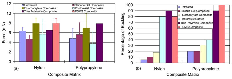
The penetration-force measurement results for the various mesh-composite materials are shown in Fig. 5. The maximum forces to penetrate the composites are shown in Fig. 5(a). The control or untreated mesh matrices required penetration forces of 6.37 ± 0.72 and 4.81 ± 2.11 mN for the nylon-and polypropylene-mesh matrices, respectively. When silicone gel was added to the mesh matrix, the penetration force interestingly decreased for the nylon-mesh composite (4.65 ± 0.84 mN) and marginally increased for the polypropylene-mesh composite (5.62 ± 2.44 mN). All the other mesh composite materials tested showed an increase in penetration force, except for the photoresist-mesh composites. However, the percentage of microelectrodes that buckled during penetration increased for the photoresist-mesh composites [Fig. 5(b)]. Thus, the sample size of photoresist composites for which the penetration force was actually reported was lower than the sample sizes of other mesh composites. The number of microelectrodes that buckled with the nylon-mesh matrices (untreated and silicone gel treated) were significantly lower than the corresponding polypropylene matrices. Overall, the nylon-mesh composites had less variability in penetration forces compared to the polypropylene-mesh-matrix composites.
Fig. 5.
Results of penetration-force measurement tests showing (a) the maximum force required for a 60-μm-wide silicon probe to penetrate through various composite materials and (b) the percentage of attempts that resulted in microelectrode buckling.
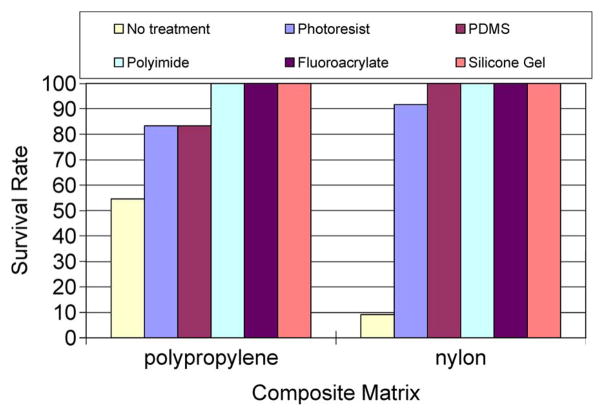
The results of the gross-leak test are shown in Fig. 6. Twelve samples of each of the materials were tested, where each material was penetrated by a 50-μm-diameter stainless-steel wire or a “Michigan probe.” The probes and wires were moved ~ 500 μm a day. Any leak detection was considered a failed material. Our setup allowed us to detect levels of < 1 μL. The control or untreated matrix materials had the lowest survival rates of 55% and 9% for the polypropylene- and nylon-mesh matrices, respectively. The silicone-gel-, polyimide-, and fluoroacrylate-mesh composites had a 100% survival rate. The photoresist- and PDMS-based mesh composites had a better survival rate (> 80%) than the untreated materials.
Fig. 6.
Results of gross-leak tests performed by immersing the packaged material into DI water for 504 h.
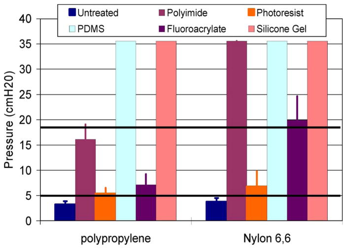
The maximum pressures that can be sustained by the mesh composites shown in Fig. 7 indicate that both nylon and polypropylene untreated matrix materials will leak fluid under normal ICPs. The maximum pressures that the two untreated meshes could withstand were 3.8 ± 0.7- and 3.3 ± 0.6-cm H2O for the nylon and polypropylene meshes, respectively, which are well below the normal physiological ICP range of 6.5–18-cm H2O. The photoresist-based mesh composites could withstand the maximum pressures of 6.8 ± 3.0- and 5.4 ± 1.1-cm H2O for the nylon- and polypropylene-mesh matrices, respectively, which are also below the normal physiological range of ICP. The silicone-gel-, PDMS-, polyimide-, and fluoroacrylate-mesh composites with a nylon-mesh matrix were all able to withstand pressures above the normal physiological range of ICP. However, only the PDMS- and silicone-gel-mesh composite with a polypropylene-mesh matrix could withstand pressures above the normal ICP.
Fig. 7.
Results showing the maximum amount of pressure that the various mesh composite materials can withstand before leakage of DI water. The black horizontal lines represent the normal limits of ICP, as seen in humans.
The results from the cytotoxicity tests shown in Fig. 8 confirm that the silicone-gel-mesh composite was nontoxic, based on the morphology of the cells. In the live–dead-cell-assay test, the living cells are stained green, whereas the dead cells are stained red. The N2a cells morphologically look good, and they are all stained green, which confirms that the cells are living. The mesh is out of focus because the cells are resting on the composite material that is not on the same layer as the mesh matrix. The cytotoxicity tests showed (data not shown) that none of the other composite materials was toxic. The density of the cells on the silicone-gel composite was comparable to the density of the cells in the control wells. The results of the live–dead-cell assay showed that there was no cell death due to the mesh composites after three days.
Fig. 8.
Results of the cytotoxicity tests using N2a cells. The live–dead-cell-assay results shown in gray (green in the color version) represent the live cells after three days. (a) Results from the control (untreated mesh) matrix. (b) and (c) Results from the silicone-gel–nylon-mesh matrix. Magnification is ten times in all the images.
All of the composites for the nylon mesh were ranked based on the different desired criteria for the encapsulation. The results of the ranking are shown in Table II. Each of the categories was ranked from 1 to 6, where 6 is the best and 1 is the worst. The highest ranked material that emerged was the silicone-gel-mesh composite. The second best choice was the fluoroacrylate-mesh composite.
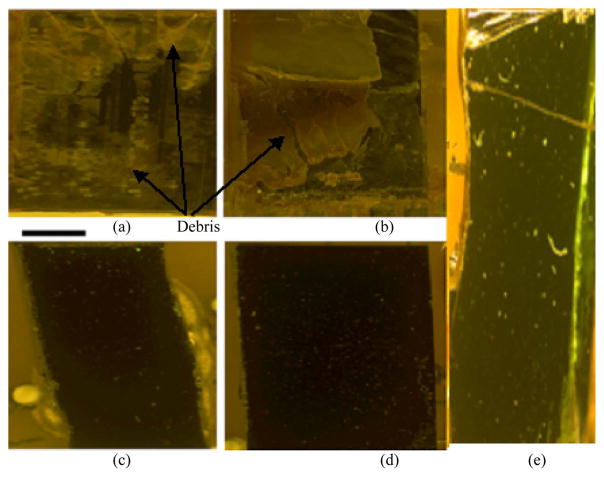
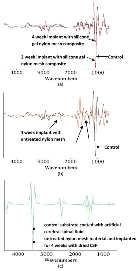
Visual inspection of the devices explanted from in vivo experiments demonstrated that the devices encapsulated with an untreated nylon-mesh matrix and implanted for over four weeks had no significant improvement over the devices shown in Fig. 2(b), which had no encapsulation material and were also implanted for over four weeks. Fluids (CSF and blood) had entered the device. Visually, the devices encapsulated with a silicone-gel-mesh composite and implanted for two and four weeks look identical to their control counterparts (Fig. 9) that were not implanted. Fig. 9(a) and (b) shows significant debris entry caused from dried-up-fluid entry. Fig. 9(c)–(e) visually shows no sign of debris or fluid entry after the devices were removed from the rat after two and four weeks. FTIR analysis (Fig. 10) showed that the surface of the silicon chip encapsulated with the silicone-gel-mesh composite and implanted for two and four weeks had similar chemical composition as the unimplanted control chips, indicating that there was no other significant foreign-body presence on the substrate of the implanted silicon chip. The FTIR data of the untreated-nylon-mesh-encapsulated chip were significantly different. The FTIR data showed a high-resonance pattern due to the SiO2 layer on top of the silicon wafer. The resonance was minimized by taking the derivative of the data using Essential FTIR (Operant LLC). The FTIR data of the unimplanted control chip are compared with those of two devices that were implanted for two and four weeks in Fig. 10(a). The FTIR spectra showed similar peaks over all the wavelengths. The FTIR data of the unimplanted control chip are compared with those of a device encapsulated with the untreated nylon-mesh matrix and implanted for four weeks in Fig. 10(b). The FTIR data of the control chip coated with artificial CSF (aCSF) is compared with the chip that was encapsulated with an untreated nylon-mesh material for four weeks in Fig. 10(c). This particular device in Fig. 10(c) showed signs of CSF entry only (no blood).
Fig. 9.
Micrographs of the implanted dummy devices. (a) and (b) Two devices with an untreated-nylon-mesh-matrix encapsulation and implanted for over four weeks. (c) and (d) Two devices with silicone-gel–nylon-mesh-composite encapsulation that were implanted for two weeks. (e) Device with silicone-gel–nylon-mesh-composite encapsulation after four weeks of implantation. The scale bar is 1 mm.
Fig. 10.
FTIR results of the implanted devices. FTIR spectra of (a) (black) control compared to (red) a two-week and (brown) a four-week implanted device encapsulated with a silicone-gel–nylon-mesh-matrix composite. (b) (Black) Control compared to (orange) a device encapsulated by an untreated nylon-mesh material (without any gel) that was implanted for four weeks. (c) (Blue) device encapsulated by an untreated nylon-mesh material and implanted for four weeks with dried CSF on its surface and (green) a control substrate coated with aCSF. The arrows without labels indicate the wavelengths where there is a change in the FTIR of the implanted devices compared to the control devices.
The results from the implanted movable microelectrode devices show that n = 1 device failed due to blood leakage (Fig. 11). The failed device allowed blood to enter the open cavity at day 7 (postimplantation), whereas the other devices (n = 5) have shown no fluid entry for up to 14 days postimplantation.
Fig. 11.
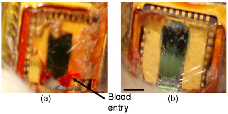
Micrographs of the implanted movable microelectrode devices with silicone-gel-mesh-composite-material encapsulation (14 days postimplantation). (a) Failed device with blood filling the open-cavity area. (b) Successful device with no sign of fluid entry into the open-cavity area. The scale bar is 3 mm.
V. Discussion
We have addressed a critical need in encapsulating a new generation of novel implantable bio-MEMS devices that involve movable components. There is a need for an encapsulation that is easy to fabricate, offers protection from fluid entry, allows easy penetration by microelectrodes, retains its integrity after penetration of the microelectrodes and repeated movement of the microelectrodes, and is biocompatible.
In order to analyze the data, the composite materials assessed in this paper were separated into two categories: 1) thin-film composites and 2) surface-modified composites. The thin-film composites included the silicone-gel-, PDMS-, and thinned polyimide-mesh composites, whereas the surface-modified composites included the photoresist- and fluoroacrylate-mesh composites. The surface-modified composites (photoresist, fluoroacrylate, and nontreated matrices) were porous, and thus, their corresponding contact angles appeared to have a direct relationship with the maximum pressure that they could withstand before leakage. Assuming that the pores in the surface-modified composites are a circle of radius R, the maximum tolerable pressure ΔP before leakage is related to the contact angle theta by the following equation, ΔP = 2 σ cos(θ)/R, where σ is the surface tension. Therefore, increasing the hydrophobicity of the matrices would cause an increase in the maximum tolerable pressure before leakage. This is verified by comparing the contact-angle measurements of photoresist, fluoroacrylate, and the untreated mesh in Table I with the results of the pressure leakage tests in Fig. 7. The fluoroacrylate and untreated meshes had the largest and smallest contact angles, respectively. Their maximum pressures before leakage were also the largest and smallest among the surface-modified materials, respectively. The pore size in the surface-modified composites was also smaller compared to the pore opening in the untreated meshes that resulted in a marginally higher pressure to be obtained before leakage. On the other hand, the polypropylene surface-modified mesh composites gave lower leakage pressure results when compared to composites made of nylon mesh because of the marginally larger pore size. However, for a thin-film composite (PDMS, polyimide, and silicone gel), the contact angle was less important as a determinant of maximum sustainable leakage pressure since the composite material was no longer porous. Thin-film composite materials, in general, required a larger pressure to cause leakage (Fig. 7).
A preferred encapsulation material for the movable microelectrode chip also requires the material to be easily penetrable by microelectrodes. The surface-modified mesh composites affect the penetration force by reducing the pore size and modifying the stiffness of the mesh. The photoresist-mesh composite became stiffer after hard baking and increased the likelihood of buckling by microelectrodes during penetration. A thin-film viscoelastic mesh composite, on the other hand, was expected to stretch and allow the microelectrodes to penetrate, even if the microelectrodes hit the threads of the mesh during penetration. The thin-film composites needed to be soft and flexible in order for the microelectrodes to easily penetrate without causing buckling. A viscoelastic encapsulation material was preferred so that the material could retain its shape after penetration. PDMS and silicone gel are both viscoelastic materials, with a hardness of 50 units using a Shore A hardness scale for PDMS and 90 g for silicone gel according to Dow Corning. The silicone gel was extremely soft and could not be measured using standard hardness scales. In contrast, polyimide was a stiffer elastic material with a modulus of 8.5 GPa. The softer the mesh composite material, the lesser the force required to penetrate through the material and the lower the likelihood of microelectrode buckling during penetration. This was verified by the low forces required to penetrate and low buckling percentage of microelectrodes through a silicone-gel-mesh composite (Fig. 5). The velocity of the microelectrode at the time of penetration also had an impact on the force requirements. Therefore, the velocity was kept constant (10 μm/s) throughout all of the measurements in this paper.
We have carefully tested and evaluated various candidate materials, of which the silicone-gel and nylon-mesh composite was the optimal choice. Force-penetration tests showed that the silicone-gel- and nylon-mesh composite required the lowest force to penetrate and had the second lowest buckling percentage that is only marginally worse than that of the untreated mesh. The reason for the decrease in penetration force for the silicone-gel- and nylon-mesh composite compared to the untreated nylon-mesh matrix was likely due to the increase in flexibility of the composite material. Most of the mesh composites resulted in a high survival rate when immersed in DI water. However, the untreated mesh matrices had a low survival rate. The silicone-gel-mesh composite, in particular, had a 100% survival rate. Pressure testing showed that the silicone-gel-mesh composite could withstand pressures that are more than double that of a normal ICP. All of the materials tested for the mesh composites were biocompatible.
Based on the previous results of the bench-top experiments and the rankings according to Table II, the silicone-gel-mesh composite was chosen for further in vivo testing by implantation. The devices that were implanted for up to four weeks with silicone-gel-mesh composite encapsulation showed no signs of fluid or any foreign-body entry based on visual assessments and FTIR measurements. However, for the device encapsulated with the untreated nylon mesh and implanted for four weeks, distinct differences were observed, particularly in the shorter wavelengths in the FTIR spectra, when compared to that of the unimplanted control device. Proteins and sugars typically found in vivo show peaks at shorter wavelengths in the FTIR spectrum according to the Essential-FTIR library. Since the FTIR data for blood or CSF are not commonly documented or available in the Essential-FTIR library, it was hard to confirm the presence of these two components solely from the FTIR data. However, visual inspection of the implanted device encapsulated with the untreated nylon mesh indicated both blood and what appeared to be CSF debris on the chip substrate, confirming the FTIR results. The results from the implanted movable microelectrode devices that were encapsulated with the silicone-gel-mesh composite showed that n = 5 out of n = 6 devices lasted for a period of at least two weeks. The failed device is likely caused from excess pressure buildup, and there was probably some small hole in the mesh material that was not properly coated with silicone gel. This suggested that the silicone-gel-mesh composite was a reliable encapsulation material for implantable movable microelectrodes. The silicone-gel composite was easy to fabricate, cured in 10–15 min, easy to penetrate, resealable, and biocompatible, and it could be fabricated relatively thin due to mesh-matrix support and could withstand physiologically relevant ICPs.
There are other mesh-matrix materials that could have been selected or fabricated with different pore sizes and threads in the mesh matrix. There are also other candidate materials, such as parylene C and other types of silicone gel. Parylene C was not tested because of its relative stiffness compared to the soft silicone gel. Furthermore, it would reduce the size of the holes and would create a uniform layer that is similar to the polyimide film, thus requiring more force to penetrate. This would likely lead to a higher buckling percentage during the penetration-force measurements. The silicone gel used in this paper was previously used as a dural sealant to allow for multiple penetrations for movable microelectrodes [19]. The problem with the use of silicone gel as a dural sealant was the inability to create a thin-enough layer for our microelectrodes to penetrate, which is now accomplished by using the mesh matrix for support. This silicone gel is extremely soft and widely used. In applications where the implant is stronger and able to withstand more force, a harder silicone gel could be used. However, the silicone gel used in this paper can be cured at room temperature in 10–15 min, can be made thin using stencil techniques, is transparent, and has a self-healing capability, which are among the several desirable features. The composite material used in this study can be easily fabricated and used by any research laboratory or prototype company without the need for complex packaging equipment.
VI. Conclusion
Two types of mesh matrices were tested (nylon 6,6 and polypropylene), and five different mesh composites using each of the aforementioned mesh matrices were made using thinned polyimide, photoresist, PDMS, fluoroacrylate, and soft silicone gel. Based on the previous bench-top and animal tests, we concluded that the optimal encapsulation material was the composite of nylon-mesh matrix with silicone gel (3-4680). This composite was consistently the easiest composite material to penetrate through with the microelectrodes, had a low percentage of microelectrodes that buckled, was the second easiest mesh composite to fabricate, and provided adequate protection from fluid entry in in vivo experiments. We conclude that this new silicon-gel–nylon-mesh composite material could be used to help provide a nonhermetic encapsulation for implantable MEMS devices to protect from fluid entry. For applications that do not need encapsulations to be penetrable by microelectrodes, the thinned polyimide-mesh composite would offer the best encapsulation. However, the fabrication process is more time consuming.
Acknowledgments
The authors would like to thank M. Khraiche for his help with the cell culture, and K. Mossman and the Center for Solid State Science for their help with the FTIR measurements.
This work was supported by National Institutes of Health Grant R01NS055312.
Biographies

Nathan Jackson (S’07–M’08) received the B.S.E. degree (summa cum laude) in bioengineering with an emphasis in bioelectrical engineering and the M.S.E. and Ph.D. degrees in bioengineering from Arizona State University, Tempe, in 2003, 2008, and 2009 respectively.
His research interests include the design and fabrication of novel biomedical microdevices, bio-MEMS, MEMS packaging, novel microelectrodes, and neural interfaces.
Dr. Jackson is a member of the International Microelectronics and Packaging Society, the IEEE Components, Packaging and Manufacturing Technology Society, and the IEEE Engineering in Medicine and Biology Society.

Sindhu Anand received the B.Eng. (Hons.) degree in electrical engineering and the M.Sc. (Hons.) degree in biological sciences from Birla Institute of Technology and Science, Pilani, India, in 2008. She is currently working toward the Ph.D. degree in bioengineering in the Harrington Department of Bioengineering, Arizona State University, Tempe.
Her research interests include the design of neural interfaces, bio-MEMS technology, and neural circuits.

Murat Okandan received the Ph.D. degree from Pennsylvania State University, University Park.
He has been with Sandia National Laboratories, Albuquerque, NM, since 1999, where he is currently with the MEMS Science and Technology Division. He has been involved in the microelectronics and microsystems arena, with expertise in solid-state device physics, microelectronics processing, and sensors. He has contributed to and leads several projects ranging from biomedical (U.S. Department of Energy (DOE) Artificial Retina Program, NIH-R01 Actuated Neural Probes) to extreme environment/highly sensitive physical sensors (shock sensors for energetic materials) and microsystem-enabled renewable energy (DOE Solar Program Seed Fund), all leveraging the unique capabilities provided by microsystems. He has authored or coauthored over 30 publications, is a holder of 12 patents (with seven pending patents), and has numerous invention disclosures.

Jit Muthuswamy (SM’06) received the B.Tech. degree in electrical and electronic communication engineering in 1991 from the Indian Institute of Technology, Kharagpur, India, and the M.S. and Ph.D. degrees in biomedical engineering in 1993 and 1996, respectively, and the M.S. degree in electrical engineering in 1996 from Rensselaer Polytechnic Institute, Troy, NY.
He is currently an Associate Professor in the Harrington Department of Bioengineering, Arizona State University, Tempe. His research interests are in bio-MEMS and in molecular and cellular mechanisms of neuronal plasticity.
Contributor Information
Nathan Jackson, Email: njack@asu.edu, nathan.jackson@asu.edu.
Sindhu Anand, Email: Sindhu.anand@asu.edu.
Murat Okandan, Email: mokanda@sandia.gov.
Jit Muthuswamy, Email: jit@asu.edu.
References
- 1.Harpster T, Nikles S, Dokmeci M, Najafi K. Long-term hermeticity and biological performance of anodically bonded glass–silicon implantable packages. IEEE Trans Device Mater Rel. 2005 Sep;5(3):458–466. [Google Scholar]
- 2.Cheung K, Djupsund K, Dan Y, Lee L. Implantable multichannel electrode array based on SOI technology. J Microelectromech Syst. 2003 Apr;12(2):179–184. [Google Scholar]
- 3.Lee KK, He J, Singh A, Massia S, Ehteshami G, Kim B, Raupp G. Polyimide-based intracortical neural implant with improved structural stiffness. J Micromech Microeng. 2004 Jan;14(1):32–37. [Google Scholar]
- 4.Moxon K, Kalkhoran N, Markert M, Sambito M, McKenzie JL, Webster J. Nanostructured surface modification of ceramic-based microelectrodes to enhance biocompatibility for a direct brain–machine interface. IEEE Trans Biomed Eng. 2004 Jun;51(6):881–889. doi: 10.1109/TBME.2004.827465. [DOI] [PubMed] [Google Scholar]
- 5.Nordhausen C, Maynard E, Normann R. Single unit recording capabilities of a 100 microelectrode array. Brain Res. 1996 Jul;726(1/2):129–140. [PubMed] [Google Scholar]
- 6.Norlin P, Kindlundh M, Mouroux A, Yoshida K, Hofmann U. A 32-site neural recording probe fabricated by DRIE of SOI substrates. J Micromech Microeng. 2002 Jul;12(4):414–419. [Google Scholar]
- 7.Vetter R, Williams J, Hetke J, Nunamaker E, Kipke D. Chronic neural recording using silicon-substrate microelectrode arrays implanted in cerebral cortex. IEEE Trans Biomed Eng. 2004 Jun;51(6):896–904. doi: 10.1109/TBME.2004.826680. [DOI] [PubMed] [Google Scholar]
- 8.Wise K, Anderson D, Hetke J, Kipke D, Najafi K. Wireless implantable microsystems: High-density electronic interfaces to the nervous system. Proc IEEE. 2004 Jan;92(1):76–97. [Google Scholar]
- 9.Becker T, Kipke D. Algel as dural sealant, determination of effects on the sensorimotor cortex in rats. Proc. 25th Annu. Int. Conf. IEEE EMBS; 2003. pp. 1972–1975. [Google Scholar]
- 10.Cham J, Branchaud E, Nenadic Z, Greger B, Anderson R, Burdick J. Semi-chronic motorized microdrive and control algorithm for autonomously isolating and maintaining optimal extracellular action potentials. J Neurophysiol. 2005 Jan;93(1):570–579. doi: 10.1152/jn.00369.2004. [DOI] [PubMed] [Google Scholar]
- 11.Park S, Yoon E, Lee S, Shin HS, Park H, Kim B, Kim D, Park J, Park S. The development of a PZT-based microdrive for neural signal recording. Smart Mater Struct. 2008 Apr;17(2):1–7. [Google Scholar]
- 12.Sato T, Suzuki T, Mabuchi K. A new multi-electrode array design for chronic neural recording, with independent and automatic hydraulic positioning. J Neurosci Methods. 2007 Feb;160(1):45–51. doi: 10.1016/j.jneumeth.2006.08.009. [DOI] [PubMed] [Google Scholar]
- 13.Keating J, Gerstein G. A chronic multi-electrode microdrive for small animals. J Neurosci Methods. 2002 Jun;117(2):201–206. doi: 10.1016/s0165-0270(02)00115-2. [DOI] [PubMed] [Google Scholar]
- 14.Nichols A, Ruffner T, Sommer M, Wurtz R. A screw microdrive for adjustable chronic unit recording in monkeys. J Neurosci Methods. 1998 Jun;81(1/2):185–188. doi: 10.1016/s0165-0270(98)00036-3. [DOI] [PubMed] [Google Scholar]
- 15.Muthuswamy J, Okandan M, Gilletti A, Baker M, Jain T. An array of microactuated microelectrodes for monitoring single-neuronal activity in rodents. IEEE Trans Biomed Eng. 2005 Aug;52(8):1470–1477. doi: 10.1109/TBME.2005.851478. [DOI] [PMC free article] [PubMed] [Google Scholar]
- 16.Muthuswamy J, Okandan M, Jain T, Gilletti A. Electrostatic microactuators for precise positioning of neural microelectrodes. IEEE Trans Biomed Eng. 2005 Oct;52(10):1748–1755. doi: 10.1109/TBME.2005.855712. [DOI] [PMC free article] [PubMed] [Google Scholar]
- 17.Pang C, Tai Y-C, Burdick J, Anderson R. Electrolysis-based parylene balloon actuators for movable neural probes. Proc. 2nd IEEE Int. Conf. Nano/Micro Eng. Mol. Syst.; Bangkok, Thailand. 2007. pp. 913–916. [Google Scholar]
- 18.Jackson N, Stice P, Okandan M, Muthuswamy J. Long-term cortical recordings with microactuated microelectrodes. Proc. 3rd Int. IEEE EMBS Conf. Neural Eng.; Kohala Coast, HI. 2007. pp. 141–143. [Google Scholar]
- 19.Jackson N, Muthuswamy J. Artificial dural sealant that allows multiple penetrations of implantable brain probes. J Neurosci Methods. 2008 Jun;171(1):147–152. doi: 10.1016/j.jneumeth.2008.02.018. [DOI] [PMC free article] [PubMed] [Google Scholar]
- 20.Adams C, Mathieson K, Gunning D, Cunningham W, Rahman M, Morrison JD, Prydderch ML. Development of flexible arrays for in vivo neuronal recordings and stimulation. Nucl Instrum Methods Phys Res A, Accel Spectrom Detect Assoc Equip. 2005 Jul;546(1/2):154–159. [Google Scholar]
- 21.Yu Z, Tsay C, Lacour S, Wagner S, Morrision B. Stretchable microelectrode arrays: A tool for discovering mechanisms of functional deficits underlying traumatic brain injury and interfacing neurons with neuroprosthetics. Proc. 28th Annu. Int. Conf. IEEE EMBS; New York, NY. 2006. pp. 6732–6735. [DOI] [PubMed] [Google Scholar]
- 22.Jackson N, Muthuswamy J. Flexible chip-scale package and interconnect for implantable MEMS movable microelectrode for the brain. J Microelectromech Syst. 2009 Apr;18(2):396–404. doi: 10.1109/JMEMS.2009.2013391. [DOI] [PMC free article] [PubMed] [Google Scholar]
- 23.Meyer JU, Stieglitz T, Scholz O, Haberer W, Beutel H. High density interconnects and flexible hybrid assemblies for active biomedical implants. IEEE Trans Adv Packag. 2001 Aug;24(3):366–374. [Google Scholar]
- 24.Cheung K, Renaud P, Tanila H, Djupsund K. Flexible polyimide microelectrode array for in vivo recordings and current source density analysis. Biosens Bioelectron. 2007 Mar;22(8):1783–1790. doi: 10.1016/j.bios.2006.08.035. [DOI] [PubMed] [Google Scholar]
- 25.Stieglitz T. Flexible biomedical microdevices with double-sided electrode arrangements for neural applications. Sens Actuators A, Phys. 2001 May;90(3):203–211. [Google Scholar]
- 26.Feili D, Schuettler M, Doerge T, Kammer S, Hoffmann K, Stieglitz T. Flexible organic field effect transistors for biomedical microimplants using polyimide and parylene C as the substrate and insulator layers. J Micromech Microeng. 2006 Aug;16(8):1555–1561. [Google Scholar]
- 27.Sun Y, Lacour S, Brooks R, Rushton N, Fawcett J, Cameron R. Assessment of the biocompatibility of photosensitive polyimide for implantable medical device use. J Biomed Mater Res A. 2009 Sep;90A(3):648–655. doi: 10.1002/jbm.a.32125. [DOI] [PubMed] [Google Scholar]
- 28.Chiao M, Lin L. Hermetic wafer bonding based on rapid thermal processing. Sens Actuators A, Phys. 2001 Jul;91(3):398–402. [Google Scholar]
- 29.Chiao M, Lin L. Device-level hermetic packaging of micro-resonators by RTP aluminum-to-nitride bonding. J Microelectromech Syst. 2006 Jun;15(3):515–522. [Google Scholar]
- 30.Lorenzl S, Koedel U, Pfister HW. Mannitol, but not allopurinol, modulates changes in cerebral blood flow, intracranial pressure, and brain water content during pneumococcal meningitis in the rat. Crit Care Med. 1996 Nov;24(11):1874–1880. doi: 10.1097/00003246-199611000-00018. [DOI] [PubMed] [Google Scholar]
- 31.Mokri B, Hunter SF, Atkinson JLD, Piepgras DG. Orthostatic headaches caused by CSF leak but with normal CSF pressures. Neurology. 1998 Sep;51(3):786–790. doi: 10.1212/wnl.51.3.786. [DOI] [PubMed] [Google Scholar]
- 32.Preul M, Bichard W, Muench T, Spetzler R. Toward optimal tissue sealants for neurosurgery: Use of a novel hydrogel sealant in a canine durotomy repair model. Neurosurgery. 2003 Nov;53(5):1189–1199. doi: 10.1227/01.neu.0000089481.87226.f7. [DOI] [PubMed] [Google Scholar]
- 33.Szarowski D, Andersen M, Retterer S, Spence A, Isaacson M, Craighead H, Turner J, Shain W. Brain responses to micro-machined silicon devices. Brain Res. 2003 Sep;983(1/2):23–35. doi: 10.1016/s0006-8993(03)03023-3. [DOI] [PubMed] [Google Scholar]
- 34.Jourdain A, De Moor P, Baert K, De Wolf I, Tilmans H. Mechanical and electrical characterization of BCB as a bond and seal material for cavities housing (RF-)MEMS devices. J Micromech Microeng. 2005 Jul;15(7):S89–S96. [Google Scholar]
- 35.Zealear D, Garren K, Rodriguez R, Reyes J, Huang S, Dokmeci M, Najafi K. The biocompatibility, integrity, and positional stability of an injectable microstimulator for reanimation of the paralyzed larynx. IEEE Trans Biomed Eng. 2001 Aug;48(8):890–897. doi: 10.1109/10.936365. [DOI] [PubMed] [Google Scholar]


