Abstract
The V3D system provides three-dimensional (3D) visualization of gigabyte-sized microscopy image stacks in real time on current laptops and desktops. Combined with highly ergonomic features for selecting an X, Y, Z location of an image directly in 3D space and for visualizing overlays of a variety of surface objects, V3D streamlines the on-line analysis, measurement, and proofreading of complicated image patterns. V3D is cross-platform and can be enhanced by plug-ins. We built V3D-Neuron on top of V3D to reconstruct complex 3D neuronal structures from large brain images. V3D-Neuron enables us to precisely digitize the morphology of a single neuron in a fruit fly brain in minutes, with about 17-fold improvement in reliability and 10-fold savings in time compared to other neuron reconstruction tools. Using V3D-Neuron, we demonstrated the feasibility of building a 3D digital atlas of neurite tracts in the fruit fly brain.
Quantitative analysis of three-, four-, and five-dimensional (3D, 4D, and 5D) microscopic data sets that involve the four dimensions of space and time and a fifth dimension of multiple fluorescent probes of different colors, is rapidly becoming the bottleneck in projects that seek to gain new insights from high-throughput experiments that use advanced 3D microscopic digital imaging and molecular labeling techniques1,2. This task is often very challenging due to (1) the complexity of the multidimensional image objects in terms of shape, e.g. neurons, and texture, e.g. subcellular organelles, (2) the large scale of the image data, which currently is in the range of hundreds of megabytes to several gigabytes per image stack, (3) the low or limited signal-to-noise ratio of the image data, and (4) the inapplicability of many two-dimensional (2D) image visualization and analysis techniques in these higher dimensional situations. Real-time 3D visualization-assisted analysis (viz-analysis) can effectively help an investigator produce and proofread biologically meaningful results in these complicated situations. It is thus highly desirable to have high-performance software tools that can simultaneously visualize large multidimensional image data sets, allow the user to interact and annotate them in a computer-assisted manner, and extract from there the quantitative analysis results.
Many existing software packages, such as Amira (Visage Imaging), ImageJ3, Chimera4, Neurolucida (MBF Bioscience), and Image Pro (MediaCybernetics), can be classified into this viz-analysis category when an image under consideration has a relatively small volume or it is primarily processed in a slice-by-slice 2D manner. The Visualization Toolkit (VTK)5 conjugated with ITK (Insight segmentation and registration toolkit)6 also provides a very useful platform for viz-analysis of 3D biomedical images. However, the performance of these tools is not yet scalable to multidimensional multi-gigabyte image data sets. We present here a new viz-analysis system called V3Ddesigned to fill this niche. V3D has two distinctive novel features. First, we crafted the visualization engine of V3D to be fast enough to render multi-gigabyte, 3D volumetric data in real time on an ordinary computer and to be scalable to an image of any size. Second, we developed methods to directly pinpoint any XYZ location in an image volume using just one or two mouse-clicks while viewing it directly in 3D. The previous alternatives were to do this in a 2D slice or to use a virtual mouse in an expensive stereo-viewing system. These two characteristics in combination make V3D suitable for performing complicated analyses of multidimensional image patterns in a user efficient way. We demonstrated the strength of V3Din this regard by developing a suite of tools for neuroscience, called V3D-Neuron. We illustrated how easy it is to reconstruct a 3D neuronal structure with V3D-Neuron. We also used the tool to produce a 3D digital atlas of stereotypical neurite tracts in a fruit fly’s brain.
Results
Real-time 3D visualization of large-scale heterogeneous data
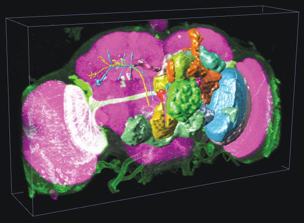
We built the cross-platform V3D visualization engine, which renders heterogeneous data including both 3D/4D/5D volumetric image data and a variety of 3D surface objects. As an example see Fig. 1a (and Supplementary Video 1) that shows a 3D view of a multi-channel image stack of a fruit fly brain, a set of surface objects corresponding to brain compartments, and several individually reconstructed neurons, all in the same view. For the multidimensional intensity data of image stacks, V3D can render a maximum intensity projection (MIP), an alpha-blending projection, and a cross-sectional view, as well as permitting arbitrary cutting planes through the image stack. For color channels that are often associated with different fluorescent molecules, V3D provides color mapping for improved visualization. V3D supports four categories of “model” objects: (1) irregular surface meshes (to model objects such as a brain compartment or a nuclear envelope), (2) spheres (as a simple proxy for globular objects such as cells and nuclei), (3) fibrous, tubular or network like structures with complicated branching and connection patterns (to describe the tree-like structure of a neuron, or other relational data or graphs of surface objects), and (4) markers (to represent various XYZ locations and often used to guide image segmentation, tracing, registration and annotation). Any combination of collections of these objects can be rendered in different colors, styles, and in different groupings, on top of an intensity-based multidimensional image. We have used these features to describe a range of digital models of microscopic image patterns, such as a 3D digital nuclear atlas model of C. elegans7 and the fruit fly brain map in Fig. 1a.
Figure 1.
V3D visualization.
(a) The use of V3D in visualizing a 3D digital model of a fruit fly brain. Magenta voxels: the 3D volumetric image of a fruit fly brain; green voxels: a 3D GAL4 neurite pattern; colored surface objects of irregular shapes: digital models of various brain compartments; colored tree-like surface objects: 3D reconstructed neurons.
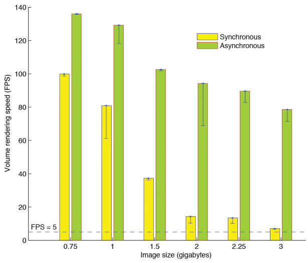
(b) The volumetric image rendering speed of V3D visualization engine under synchronous and asynchronous modes. For each image size, both the peak speed (green and yellow bars) and the respective standard deviation (black line-ranges) of at least 10 speed-test trials are shown. The tests were done on a 64bit Redhat Linux machine with a GTX280 graphics card.
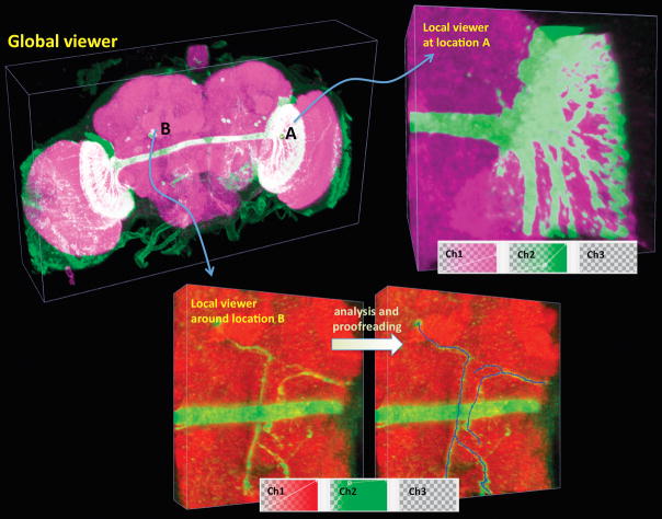
(c) V3D hierarchical visualization and analysis. Local 3D viewers of different brain regions can be conveniently initialized from the global viewer. Local viewers can have their own color maps and surface objects independent of the global viewer. They can also be used to analyze sub-volumes of an image separately.
V3D permits interactive rotation, zoom, and pan via mouse movement. The speed of V3D visualization engine is one of the key factors to its usability. It is well known that the 3D volumetric image visualization is computationally expensive. To enable real time 3D rendering of gigabytes of volumetric image data, we first optimized the synchronous rendering of 4D red-green-blue-alpha (RGBA) images using OpenGL 2D or 3D texture mapping, at the full resolution. This resulted in an MIP rendering at rates of 15 and 8 frames per second (FPS) in our tests of 2.25- and 3-gigabyte red-green-blue (RGB) colorimetric images (1024 × 1024 × 768 and 10243 voxels, respectively) on a 64-bit Linux machine (Dell Precision T7400) with only 1-gigabyte of graphics card memory (Nvidia GTX280) (Fig. 1b). A number of studies show that 5-FPS gives a satisfactory interactive experience8, indicating that V3D synchronous rendering is sufficiently fast for multi-gigabyte images. We further designed an asynchronous rendering method performing at almost 80 FPS for a 3-gigabyte image, a 10-fold improvement in speed (Fig. 1b). To do so, we took advantage of the fact that human eyes are not sensitive to the details of a moving object and can only distinguish such details when an object is still. Therefore, in the asynchronous mode, when a user is rotating, or using other ways to interact with a large image, V3D renders a medium-resolution representation of this image. Once such an interaction is over, V3D displays the full resolution. This asynchronous method achieves both the high resolution and high speed; it is largely independent of the graphics cards used, and is limited by the bandwidth of the PCIe (peripheral component interconnect express) connection of the underlying computer. We achieved a similar speed improvement on different test machines, such as a Mac Pro with a 512-megabyte graphics card (Supplementary Fig. 1).
The only restriction on image size forV3D is that there should be sufficient memory on the underlying hardware. For very large images, e.g. 8–32 gigabytes, or an older machine, the interaction speed becomes an issue. To alleviate this issue V3D has two 3D viewers for an image stack: a global viewer and another local viewer of a region of interest dynamically specified by the user (Fig. 1c, Supplementary Videos 2a, 2b and 2c). This combination of dual 3D viewers allows immediate visualization of any details of a large image stack. Viz-analysis can be performed in both global and local 3D viewers.
Direct 3D pinpointing of 3D image content
Direct user interaction with the content of a volumetric image requires a user to select one or more points in 3D space, these being recorded as markers described earlier. To complement our fast V3D 3D-viewer, we developed two 3D point selection methods that work simply in 3D space without the need for any stereo-viewing hardware or virtual reality equipment.
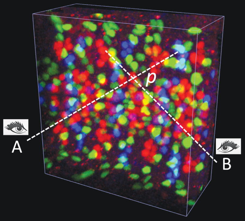
The first method prompts a user to mouse-click on a point of interest twice, each from a different viewing angle (Fig. 2a, Supplementary Video 3a). Each click defines a ray through the cursor location orthogonal to the screen. V3D creates a marker at the point in space for which the sum of its Euclidean distance to each ray is minimal (this is to allow for some slight displacement/inaccuracy in the user’s 2D clicks). This method is independent of the color channels of the image.
Figure 2.
3D pinpointing methods of V3D.
(a) 3D pinpointing using 2 mouse-clicks. The color image is a 3D confocal image of neurons, fluorescently tagged for three different transcriptional factors (repo, eve, and hb9) at the same time, in a fruit fly embryo. A and B: non-parallel rays generated at two viewing angles, corresponding to two mouse-clicks; p: the estimated 3D location that is closest to both A and B.
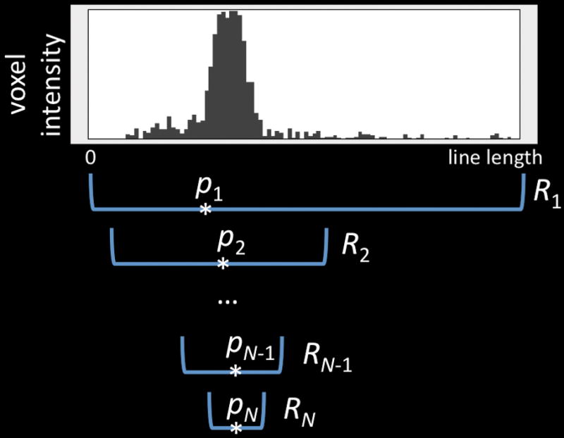
(b) 3D pinpointing using 1 mouse-click. p1 to pN: the progressively estimated centers of mass; R1 to RN: the progressively smaller intervals to estimate p1 to pN.
The second method pinpoints a 3D marker with just one mouse-click (Fig. 2b, Supplementary Video 3b). Because in this case there is only one ray defined by the click, we estimated the most probable location on the ray that the user intended by looking at the intensity information in a given image color channel. We used the mean-shift algorithm9 that begins by finding the center of mass (CoM) of the projection ray, and then repeatedly re-estimates a CoM using progressively smaller intervals around the proceeding CoM until convergence. This heuristic is very robust in estimating the desired 3D location in real data sets. When there are multiple color channels, the user specifies which one by pressing a number key, e. g. ‘1’, ‘2’, while clicking the mouse.
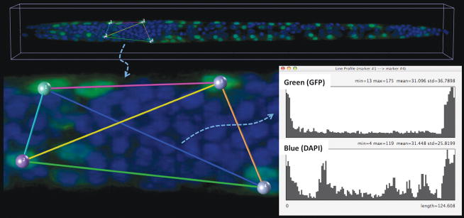
3D pinpointing is useful for measuring and annotating of any 3D spatial location in a multidimensional image (Supplementary Fig. 2), as well as providing manually selected seeds for more complex viz-analyses and for manually correcting the output of such analyses. For instance, one can quantitatively profile the voxel intensity along the straight line-segment connecting a pair of markers. Thus we could quickly measure the gradient of fluorescently labeled gene expression along an arbitrary direction in an image of C. elegans (Fig. 3). We also used 3D pinpointing to quickly count the number of neurons in the arcuate nucleus of a mouse brain (Supplementary Video 4), and to examine the relative displacement of neurons in a 5D image series of a moving C. elegans that was produced by selective plane illumination microscopy (Supplementary Figs. 3a, 3b, and 3c, Supplementary Video 5).
Figure 3.
Quantitative measuring of 3D gene expression gradient in a C. elegans confocal image. Green voxels: myo3:GFP-tagged body wall muscle cells; blue voxels: DAPI (4,6-diamidino-2-phenylindole)-tagged nuclei for the entire animal; colored spheres: pinpointed markers; colored line-segments: the line-indicator for measuring along different directions and with different starting and ending locations; line profile graph: the channel-by-channel display of the voxel intensity along a line segment.
V3D-Neuron: 3D visualization-assisted reconstruction of neurite structures
Digital reconstruction or tracing of 3D neurite structures is one of the essential yet bottleneck steps in understanding brain circuit structure and function10. We developed V3D-Neuron to trace the 3D structure of a neuron or a neurite tract from images. V3D-Neuron also immediately displays the tracing results superimposed upon the raw image data, letting one proofread and correct the tracing results interactively.
We reconstructed a neuron (Fig. 4, Supplementary Video 6) based on automated searching of the optimal “paths” connecting a set of 3D markers, which are locations pinpointed by a user to indicate where the tracing should begin and end (Fig. 4a). Our algorithm finds a smooth tree-like structure in the image voxel domain to connect one marker (root) to all remaining markers with the least “cost” defined below. We treated individual image voxels as graph vertexes, and defined graph edges between the spatial neighboring voxels. The weight of an edge is defined as the product of the inversed average intensity of the two neighboring voxels and their Euclidean distance. The least cost path between a pair of markers will be the one that goes through the highest intensity voxels with the least overall length. We used the Dijkstra algorithm11 to find the shortest paths (parent-vertex lists) from every non-root marker to the root. We detected in these lists the vertexes where two or more paths merge. These vertexes were treated as the branching points of the reconstructed neuron tree. Subsequently, we represented the traced neuron using the individual segments that connect markers and branching points (Fig. 4b), which can be easily edited in 3D whenever needed. For each segment, V3D-Neuron lets an investigator optionally refine its skeleton using a deformable curve algorithm12 that fits the path as close as possible to the “midline” of the image region of this segment. In most cases, this not only leads to a smoother path that better approximates the skeleton of a neuron (Fig. 4c), but also more accurately estimates the radius of the traced neuron along this skeleton.
Figure 4.
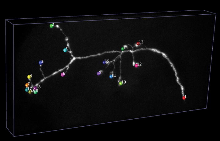
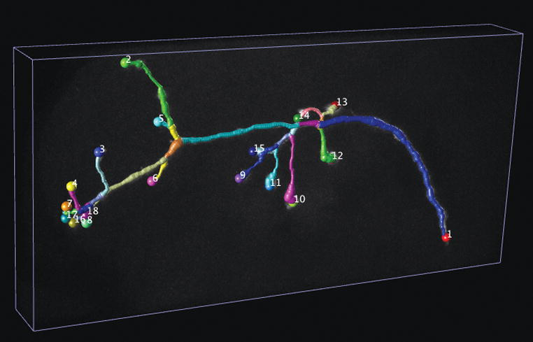
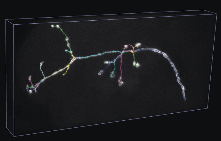
V3D-Neuron tracing.
(a) Pinpointing terminals of a fruit fly neuron. 3D image: a GFP-tagged neuron produced via twin-spot MARCM; colored spheres: markers defined for the tips of this neuron.
(b) 3D reconstructed neuron produced by V3D-Neuron. Colored segments: the automatically reconstructed neurite structures.
(c) The skeleton view of the 3D reconstructed neuron.
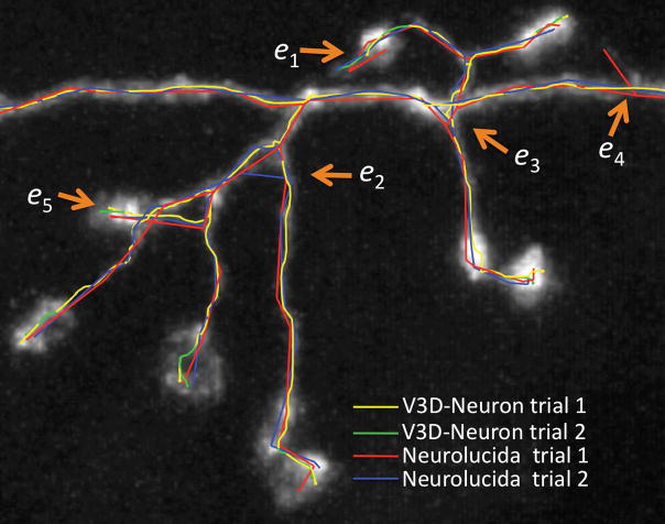
We evaluatedV3D-Neuron using 10 single neurons in the adult fruit fly brain, stained using the twin-spot MARCM technique13. This data was challenging due to the unevenness of the fluorescent signal and sharp turns in neurites. Each neuron was traced twice independently. V3D-Neuron allowed us to reconstruct each neuron and corrected the potential errors in typically 3 to 5 minutes. Compared to the state-of-the-art 2D manual reconstruction tool of Neurolucida (also with two independent tracings for each neuron), V3D-Neuron avoided the inconsistent structures in manual tracing (see e1–e4 in Fig. 5a), which were due to human variation during distinct trials. The difference of V3D-Neuron reconstructions occurred mostly at the tips of the neurons (e5 in Fig. 5a) because of the human variation in pinpointing terminal markers. Quantitatively, V3D-Neuron reconstructions have a sub-pixel precision, while the manual reconstructions have a remarkably bigger variation for the entire structure (Fig. 5b). Taking a closer look at the proportion of neuron skeletons that have visible deviation (i.e. > 2 voxels) between two trials, we found on average only 1.26% of the total path length of a reconstruction was this far from its counterpart when traced with V3D-Neuron, whereas the same statistic was 21.8% for Neurolucida (Fig. 5c). In addition, producing the reconstruction in V3D-Neuron took an order of magnitude less time, as we spent more than 2 weeks obtaining the Neurolucida results. A comparison between V3D-Neuron and other tools (e.g. Image Pro, see Supplementary Note) also showed V3D-Neuron was superior.
Figure 5.
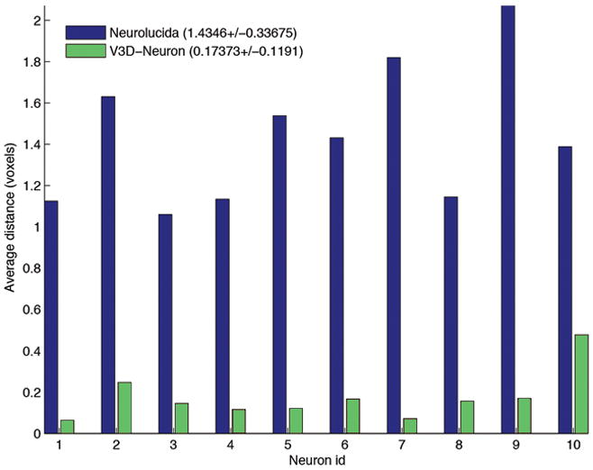
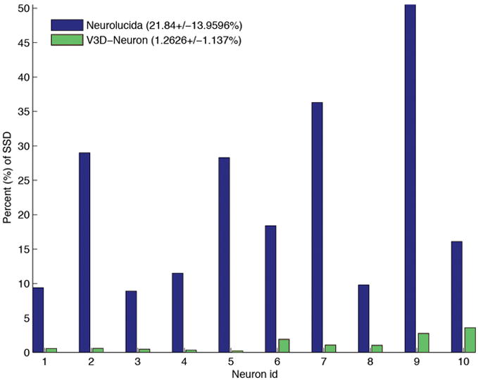
The accuracy of V3D-Neuron reconstructions compared with manual reconstructions.
(a) Inconsistency of independent trials of reconstructions. e1, e2, e3, e4: examples of the obvious inconsistent parts in manual reconstructions; e5: an example of the inconsistent region in V3D-Neuron reconstructions.
(b) The spatial divergence of reconstructed neurons using different methods, each with two independent runs. Also shown in the legend are the average and the standard deviation of the spatial divergence (see Methods) of all neurons.
(c) The percent of the neuron structure that noticeably varies in independent reconstructions. Also shown in the legend are the average and the standard deviation of this score over all neurons. SSD: substantial spatial distance.
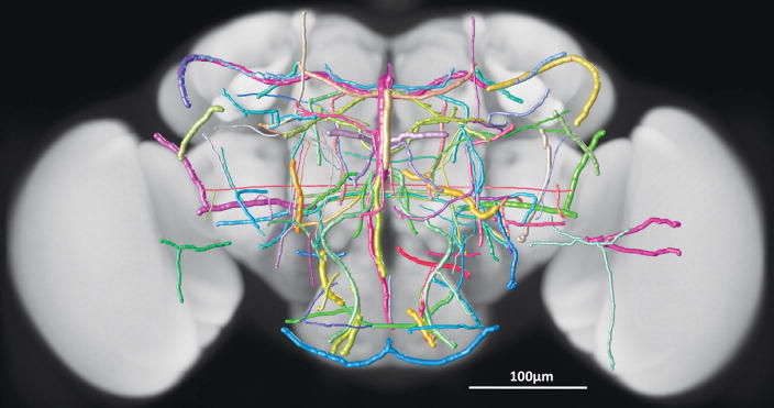
We used V3D-Neuron to reconstruct a preliminary 3D “atlas” of neurite tracts in a fruit fly brain to demonstrate the feasibility of using this tool to build a comprehensive atlas. We started with more than 3,000 confocal image stacks of the adult fruit fly brain taken of 500 fruit fly enhancer trap GAL4 lines (unpublished work of J.H. Simpson’s lab). After these images were deformably aligned to a “typical” brain using an NC82 intensity pattern in a separate channel (unpublished work of H. Peng’s lab), we used V3D-Neuron to trace 111 representative neurite tracts that project throughout the brain (Fig. 6a, Supplementary Video 7). We reconstructed 2 to 6 instances of each tract from multiple replicate images of the same GAL4 line. We produced a “mean” tract model for each group of reconstructed instances and the average deviation of members of the group from this mean. The overall shape and relative positions of these tracts are very reproducible as evidenced by deviations in the range from 0.5 to 3μm (Fig. 6b). This variance is an upper bound on the biological variability, as some portion of it was due to alignment optimization differences. Compared to the typical size of an adult fruit fly brain (590 μm × 340 μm × 120 μm), the deviations are very small, indicating that the layout of these neural tracts is highly stereotyped in a fruit fly brain.
Figure 6.
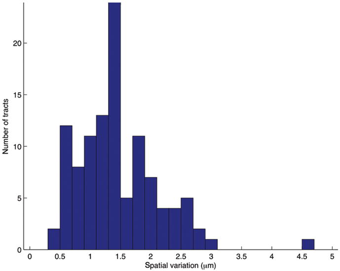
An atlas of stereotyped neurite tracts in a fruit fly brain.
(a) Statistical models of the 3D reconstructed neurite tracts. Grayscale image: a fruit fly brain; each colored tubular structure: the average of multiple neurite tracts reconstructed from images of the same GAL4 line. The width of the each tract equals twice of the spatial variation of the respective group of reconstructions.
(b) Distribution of the spatial variation of all neurite tracts.
Discussion
V3D provides a highly efficient and ergonomic platform for visualization-based bioinformatics. In particular, it features two critical and advantageous techniques, i.e. a responsive 3D viewer for multi-gigabyte volumetric image data and a 1- or 2-click pinpointing method, that facilitates rapid computer-assisted analyses and proofreading of the output of such analyses, or of fully automatic analyses. The software runs on all major computer platforms (Mac, Linux, and Windows), is further enhanced by various built-in V3D toolkits, and is extensible via user-developed plug-ins (Methods). Compared to many existing viz-analysis tools, V3D provides not only real-time visualization of large multidimensional images, but also the ability to interact with and quantitatively measure the content of such images directly in 3D. In addition, V3D is freely available, another important aspect that many expensive tools, such as Amira, Neurolucida and Image Pro, can hardly compare with.
V3D is a general tool and can be applied to analyzing any complicated image patterns. Its wide use can be seen in various examples of several model animals, ranging from measuring C. elegans’s single-nucleus gene expression level in 3D and locations of cells in 5D, to building a fruit fly neurite tract atlas and counting cells in a mouse brain. Particularly, we focus on neuroscience applications because first it represents one of the most complicated situations of bioimage visualization and analysis, and second it is of biological significance in reverse engineering a brain. V3D comes with a carefully designed graphical user interface, and supports the most common file formats. These features make it useful not only for neuroscience, but also in molecular and cell biology, and general biomedical image engineering.
The emerging flood of multidimensional cellular and molecular images poses enormous challenges for the image computing community. However, automated high-throughput analyses of complex bioimage data are still in their infancy and perfect fully automated approaches are very difficult to achieve. In this light, it is crucial to have powerful real-time visualization-assisted tools like V3D to help develop, debug, proofread, and correct the output of automated algorithms. Indeed, we have already used V3D in developing a number of automatic image analysis methods, including 3D cell segmentation7, 3D brain registration, and 3D neuron structure comparison, to name a few in addition to V3D-Neuron. Some of them, e.g. the 3D brain registration algorithm, are being deployed in the high-throughput automatic mapping of the 3D neuroanatomy of a fruit fly (unpublished work of H. Peng’s lab).
Our neurite tracing algorithm in V3D-Neuron uses both global cues supplied by a user and local cues generated automatically from the image data. This integration of both top-down and bottom-up information is particularly effective when only part of the neurite present in an image needs to be reconstructed (e.g. one neuron out of several) or the signal to noise ratio is low. Our method complements existing neuron reconstruction algorithms14,15,16,17,18 in that they can be incorporated as plug-ins so that they could be invoked from V3D, possibly with some guiding marker information, and then their results proofread and corrected in a faster and more accurate way.
The degree to which the gross and fine-scale anatomy of fly neurons is stereotyped is a question of biological significance and hot debate19,20. Computationally, the stereotypy of neurite locations found in this work indicates that we may expand our database, and use it to retrieve and catalog unknown fruit fly neurite patterns. Such information will be useful in modeling the 3D anatomical projection and connectivity diagrams of neurons in a brain, and in investigating neuron functions. We demonstrated that V3D-Neuron, in combination with our image alignment software, is a valuable new tool for addressing these questions with flexibility and quantitative precision. It is applicable to a wide range of organisms and at different imaging scales. V3D and V3D-Neuron also have the potential to allow one to manipulate the image data in real-time during functional imaging.
Methods
V3D design
We developed V3D using C/C++. We used Qt libraries (Nokia) for developing the cross-platform user interface. V3D can be compiled as either a 32-bit or a 64-bit program; the latter can load and save multi-gigabyte and bigger image stacks.
The V3D visualization engine optimizes OpenGL calls to maximize the 3D rendering throughput of a computer graphics card. We rendered volumetric data and surface data separately. For volumetric data, we considered a 4D image stack as the basic display object. A 4D image with any number of color channels is always mapped to RGBA channels for rendering. Then at a user’s choice, the V3D visualization engine produces either 2D or 3D textures for OpenGL to render the colormetric 3D volume image. V3D visualization engine also detects automatically a graphics card’s data compression capability, and lets the user be able to control that. V3D allows a user to switch between synchronous and asynchronous modes for volumetric rendering. In the asynchronous mode, V3D renders a medium size representation while a user is interacting with the currently displayed volume image, and renders the full size image once such interaction (e.g. rotating, zooming) is over. The medium-size volume, which has 512 × 512 × 256 RGB voxels by default and can be enlarged if the graphics card has enough memory, is good for visual inspection of image details in most practical cases we have tested. For each image, V3D has a default global 3D viewer and a dynamically generated local 3D viewer for any region of interest. Both the global and local viewers in V3D can use either the synchronous or asynchronous rendering methods for viz-analysis. Since the local 3D viewer often uses a much smaller volume than the entire image, we often reduced radically the time of an analysis by aggregating the viz-analysis results in multiple dynamically invoked local 3D viewers. The volumetric rendering of a 5D image was built upon rendering a series of 4D image stacks, each of which corresponds to a time point. For 3D surface data, V3D visualization engine uses an object list to manage the rendering of irregular surface meshes (for surface objects of any shape, e.g. brain compartments), spherical objects (for point cloud objects, e.g. cells, nuclei), tubular objects with branches (e.g. neurons, or user-defined line segments), and markers (user-defined XYZ locations). These surface objects can be displayed as solid surface, wiring frame, semi-transparent surface, or contours. For the tubular objects with branches, V3D has an additional skeleton display mode. These different visualization methods make it easy to observe an image and the respective surface objects. They are very useful for a number of tasks, e.g. developing new image analysis algorithms, proofreading image analysis results, and annotating the image content or surface objects.
A user can enhance V3D by developing plug-in programs. We designed very simple V3D application interfaces for writing plug-ins. A plug-in program can request V3D to supply a list of currently opened images, as well as the markers and the regions of interest a user may have defined for these images. After processing any of these data, a plug-in can display the results in either an existing window or a new image viewer window. In this way, it is convenient for anybody to use the V3D visualization engine and 3D interaction of image content to develop new image processing tools. For instance, to enhance the image file format support, we have implemented a V3D plug-in to call the Bio-Formats Java library (http://www.loci.wisc.edu/software/bio-formats), so that V3D is able to read almost 30 other image file formats in addition to the most common file formats already supported by the V3D main program.
V3D lets one annotate any XYZ location and measure the statistics of image voxels, including the mean intensity, peak intensity, standard deviation, volume, anisotropy of the shape of the local image patterns in a local region around this 3D location (Supplementary Fig. 2). Because for fluorescent images these statistics usually are associated with biological quantities such as gene expression, V3D makes it possible to quickly generate a data table of measurements of gene expression and protein abundance in a number of 3D regions. We can use this function to measure the gene expression for a C. elegans at any 3D location, without computationally segmenting a nucleus using a more sophisticated approach in an earlier study7. V3D also supports other types of quantitative measuring, including profiling voxel intensity along a straight line (Fig. 3), profiling the length and the number of branches of a neuron, etc.
V3D-Neuron design and algorithm
To model a neuron (or neurite) digitally, we developed a suite of new 3D tracing, 3D visualization, 3D editing, and 3D comparison methods on top of V3D. These functions all together are called V3D-Neuron. The version of V3D-Neuron reported here is 1.0.
We modeled a 3D traced neuron as a graph of “reconstruction nodes (vertexes)”. Each node is described as a sphere centered at a 3D XYZ location p. The diameter of the sphere, r, quantifies the width of neurite fiber at this location. The value r is defined as the diameter of the largest surrounding sphere centered at p but at the same time within this sphere at least 90% (or 99% at a user’s choice) of image voxels are brighter than the average intensity of all image voxels. To describe this graph, we used the SWC format21. Through a single run of the tracing algorithm, V3D-Neuron produces a tree graph, or a line graph if there is no branching point. Through multiple sequential reconstruction steps, V3D-Neuron is able to produce a forest of these trees, or looped graphs. In another word, V3D-Neuron is able to capture any complicated structures of neurites.
V3D-Neuron tracing method integrates both the shortest path algorithm and the deformable curve algorithm. It is fast and robust. In V3D-Neuron we also provided several ways for a user to optionally optimize the performance. We allowed using only the set of image voxels whose intensity is greater than the average voxel intensity of the entire image in the shortest path computation. We also allowed considering only 6 neighboring voxels along X, Y, and Z directions of a 3×3×3 local cube, instead of using all the 26 neighbors, in formulating the shortest path search. These optimizations substantially accelerate our algorithm. We are also developing other methods, such as detecting the 3D markers automatically, to improve the V3D-Neuron tracing. While we believe the 3D interactive tracing in V3D-Neuron is a merit but not a caveat, V3D-Neuron of course can also reconstruct a neuron in an off-line (non-interactive) manner, similar to all other conventional off-line automatic neuron tracing methods.
V3D-Neuron visualizes in 3D the reconstructed digital model of a neuron right away. We overlaid a reconstruction on top of the raw image in several ways (Supplementary Video 8): (1) display the entire model; (2) display a portion of the model at a user’s choice; (3) display only the skeleton of the model; (4) display the model semi-transparently; (5) display the contour of the model. These different methods can also be combined in visualizing and proofreading a reconstruction. In this way, it is straightforward to tell whether or not in the reconstruction there is any error, which can be corrected easily using the 3D editing function below.
In the 3D editing mode (Supplementary Video 9), V3D-Neuron automatically represents the entire neuron model as the aggregation of segments, each of which is bounded by a pair of tip or branching nodes. V3D-Neuron renders each segment using a different color, lets a user to edit in 3D directly its type (axon, dendrite, apical dendrite, soma, or a user-defined type), scale its diameter, and allows deleting it if this segment is deemed to be wrong. Each segment can also be broken into smaller pieces, which can be further edited in the same way. V3D-Neuron can scale, rotate, mirror, and translate a neuron in 3D. It also allows annotating a neuron using user-supplied information, and undo/redo operations.
V3D-Neuron can also be used to compare the similarity of multiple neurons. It can display many neurons in the same window in 3D, thus allows visual comparison of their structures (Supplementary Video 10). Moreover, it displays the basic information of the morphology of a neuron, including the total length, the number of branches, number of tips, number of segments. It also provides a method to compute the spatial “distance” (SD) of any two neurons. To compute the distance, we first spatially resampled the neuron model so that the distance between adjacent reconstruction nodes is 1 voxel in the 3D space. Then we computed the directed divergence of neuron A from neuron B, or DDIV(A,B), as the average Euclidean distance of all the resampled nodes in A to B. Finally the undirected spatial distance between A and B, SD(A,B) is defined as the average of DDIV(A,B) and DDIV(B,A). SD(A,B) is a good indicators of how far away of A and B. However, when A and B are fairly close, SD(A,B) does not well quantify the amount of different portions of the two structures. Therefore, we defined another score called substantial spatial distance (SSD), which is the average distance of all resampled nodes that are apart from the other neuron at least 2 voxels. The percentage of resampled nodes that are substantially distal to the counterpart neuron is a robust indicator of how inconsistent of these two neurons’ structures. Indeed, for the results in Fig. 5, the SSD scores of V3D-Neuron reconstructions and manual reconstructions are similar, both about 3 voxels. This is because the major SSD parts of V3D-Neuron reconstructions are at the neuronal terminal regions where the variation of human pinpointing is about 3 voxels, similar to that produced using the Neurolucida tool. However, the percentage of SSD nodes of manual reconstructions is much bigger than that of V3D-Neuron reconstructions (Fig. 5c). When two neurons are spatially apart from each other, SD and SSD scores have comparable values. Of course, when an image is quite dark to see, the 3D pinpointing variation of human subjects becomes more pronounced, which may accordingly enlarge the variation of the paths detected by V3D-Neuron.
Data and Software
The V3D software can be freely downloaded from http://penglab.janelia.org/proj/v3d. Additional tutorial movies and test data sets are available at the same web site. The database of stereotyped neurite tracts is provided at http://penglab.janelia.org/proj/flybrainatlas/sdata1_flybrain_neuritetract_model.zip. The entire database can be conveniently visualized using the V3D software itself (Supplementary Video 10).
Supplementary Material
Acknowledgments
This work is supported by Howard Hughes Medical Institute. We thank Lam B., Yu Y., Qu L., and Zhuang Y. in helping reconstruction of neurites, Yu Y. and Qu L. for developing some V3D plug-ins, Kim S., Liu. X., for C.elegans confocal images, Kerr R. and Rollins B. for the 5D C. elegans SPIM images, Lee T. and Yu H. for single neuron images, Doe C. for fruit fly embryo images, Jenett A. for fly brain compartments, Chung P. for the raw images of fruit fly GAL4 lines, Sternson S. and Aponte Y. for the mouse brain image, Eliceiri K. and Rueden C. for assistance in implementing a V3D plug-in. We also thank Rubin G., and Kerr R. for helpful comments on the manuscript.
Footnotes
Author Contributions
H.P. designed this research and developed the algorithms and systems, did the experiments and wrote the manuscript. Z.R. and F.L. helped develop the systems. J.H.S. provided raw images for building the neurite atlas. E.W.M. supported the initial proposal of a fast 3D volumetric image renderer. E.W.M., F.L., and J.H.S. helped write the manuscript.
References
- 1.Peng H. Bioimage informatics: a new area of engineering biology. Bioinformatics. 2008;24(17):1827–1836. doi: 10.1093/bioinformatics/btn346. [DOI] [PMC free article] [PubMed] [Google Scholar]
- 2.Wilt BA, Burns LD, Wei Ho ET, Ghosh KK, Mukamel EA, Schnitzer MJ. Advances in light microscopy for neuroscience. Annual Rev Neurosci. 2009;32:435–506. doi: 10.1146/annurev.neuro.051508.135540. [DOI] [PMC free article] [PubMed] [Google Scholar]
- 3.Abramoff MD, Magelhaes PJ, Ram SJ. Image Processing with ImageJ. Biophotonics International. 2004;11(7):36–42. [Google Scholar]
- 4.Pettersen EF, Goddard TD, Huang CC, Couch GS, Greenblatt DM, Meng EC, Ferrin TE. UCSF Chimera-a visualization system for exploratory research and analysis. J Comput Chem. 2004;25(13):1605–1612. doi: 10.1002/jcc.20084. [DOI] [PubMed] [Google Scholar]
- 5.Schroeder W, Martin K, Lorensen B. Visualization Toolkit: An Object-Oriented Approach to 3D Graphics. 4. (Hardcover), Kitware, Inc; Clifton Park, NY: 2006. [Google Scholar]
- 6.Yoo T. Insight into Images: Principles and Practice for Segmentation, Registration, and Image Analysis. A K Peters, Ltd; Wellesey, MA: 2004. [Google Scholar]
- 7.Long F, Peng H, Liu X, Kim S, Myers EW. A 3D digital atlas of C. elegans and its application to single-cell analyses. Nature Methods. 2009;6(9):667–672. doi: 10.1038/nmeth.1366. [DOI] [PMC free article] [PubMed] [Google Scholar]
- 8.Chen JYC, Thropp JE. Review of Low Frame Rate Effects on Human Performance. IEEE Trans Systems, Man, and Cybernetics, -Part A: Systems and Humans. 2007;37(6):1063–1076. [Google Scholar]
- 9.Fukunaga K, Hostetler LD. The Estimation of the Gradient of a Density Function, with Applications in Pattern Recognition. IEEE Trans Information Theory. 1975;21:32–40. [Google Scholar]
- 10.Roysam B, Shain W, Ascoli GA. The central role of neuroinformatics in the national academy of engineering’s grandest challenge: reverse engineer the brain. Neuroinformatics. 2009;7:1–5. doi: 10.1007/s12021-008-9043-9. [DOI] [PMC free article] [PubMed] [Google Scholar]
- 11.Dijkstra EW. A note on two problems in connexion with graphs. Numerische Mathematik. 1959;1:269–271. [Google Scholar]
- 12.Peng H, Long F, Liu X, Kim S, Myers E. Straightening C. elegans images. Bioinformatics. 2008;24(2):234–242. doi: 10.1093/bioinformatics/btm569. [DOI] [PMC free article] [PubMed] [Google Scholar]
- 13.Yu H, Chen C, Shi L, Huang Y, Lee T. Twin-spot MARCM to reveal the developmental origin and identity of neurons. Nature Neuroscience. 2009;12:947–953. doi: 10.1038/nn.2345. [DOI] [PMC free article] [PubMed] [Google Scholar]
- 14.Al-Kofahi K, Lasek S, Szarowski D, Pace C, Nagy G, Turner JN, Roysam B. Rapid automated three-dimensional tracing of neurons from confocal image stacks. IEEE Transactions on Information Technology in Biomedicine. 2002;6(2) doi: 10.1109/titb.2002.1006304. [DOI] [PubMed] [Google Scholar]
- 15.Al-Kofahi K, Can A, Lasek S, Szarowski DH, Dowell-Mesfin N, Shain W, Turner JN, Roysam B. Median-based robust algorithms for tracing neurons from noisy confocal microscope images. IEEE Transactions on Information Technology in Biomedicine. 2003;7:302–317. doi: 10.1109/titb.2003.816564. [DOI] [PubMed] [Google Scholar]
- 16.Wearne SL, Rodriguez A, Ehlenberger DB, Rocher AB, Hendersion SC, Hof PR. New Techniques for imaging, digitization and analysis of three-dimensional neural morphology on multiple scales. Neuroscience. 2005;136:661–680. doi: 10.1016/j.neuroscience.2005.05.053. [DOI] [PubMed] [Google Scholar]
- 17.Zhang Y, Zhou X, Degterev A, Lipinski M, Adjeroh D, Yuan J, Wong STC. Automated neurite extraction using dynamic programming for high-throughput screening of neuron-based assays. NeuroImage. 2007;35(4):1502–1515. doi: 10.1016/j.neuroimage.2007.01.014. [DOI] [PMC free article] [PubMed] [Google Scholar]
- 18.Meijering E, Jacob M, Sarria J, Steiner P, Hirling H, Unser M. Design and validation of a tool for neurite tracing and analysis in fluorescence microscopy images. Cytometry. 2004;58A:167–176. doi: 10.1002/cyto.a.20022. [DOI] [PubMed] [Google Scholar]
- 19.Jefferis GS, Potter CJ, Chan AM, Marin EC, Rohlfing T, Maurer CR, Jr, Luo L. Comprehensive maps of Drosophila higher olfactory centers: spatially segregated fruit and pheromone representation. Cell. 2007;128:1187–1203. doi: 10.1016/j.cell.2007.01.040. [DOI] [PMC free article] [PubMed] [Google Scholar]
- 20.Murthy M, Fiete I, Laurent G. Testing odor response stereotypy in the Drosophila mushroom body. Neuron. 2008;59(6):1009–1023. doi: 10.1016/j.neuron.2008.07.040. [DOI] [PMC free article] [PubMed] [Google Scholar]
- 21.Cannon RC, Turner DA, Pyapali GK, Wheal WH. An on-line archive of reconstructed hippocampal neurons. J Neurosci Methods. 1998;(84):49–54. doi: 10.1016/s0165-0270(98)00091-0. [DOI] [PubMed] [Google Scholar]
Associated Data
This section collects any data citations, data availability statements, or supplementary materials included in this article.


