Abstract
We developed a novel concept of using a negative acoustic lens to increase the acceptance angle of an unfocused large-area ultrasonic transducer (detector), leading to more than two fold improvement of the tangential resolution in both thermoacoustic and photoacoustic tomography. In both thermoacoustic and photoacoustic tomography, for a given transducer bandwidth, the aperture size of the detector affects the tangential resolution greatly when the object of interest is near the detector surface. We were able to overcome such tangential resolution deterioration by attaching an acoustic concave lens, made of acrylic in front of the flat detector surface. We then quantified the tangential resolution improvement using phantom images. We also showed that the use of the negative lens preserves the shape of an object after the image is reconstructed.
Keywords: thermoacoustic tomography, photoacoustic tomography, negative acoustic lens, tangential resolution
Introduction
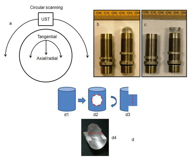
In thermoacoustic and photoacoustic tomography (TAT and PAT, respectively) a wideband ultrasonic transducer detects the acoustic signal generated due to thermoelastic expansion of tissue upon microwave/laser irradiation.1–17 From the detected acoustic signal we map back the electromagnetic (EM) absorption distribution of tissue, which is useful for diagnostic and treatment purposes. In a planer circular scanning geometry the transducer is rotated around the sample in a full circle and signals are collected. A delay-and-sum algorithm is used to reconstruct the TAT/PAT images from the raw data.18,19 Spatial resolution is one of the important parameters in both TAT and PAT. Figure 1(a) shows how radial and tangential resolutions are defined for planer circular scanning. Various factors affect the spatial resolution, but the two main limiting factors are the finite bandwidth of the ultrasound detection system and the size of the detector aperture. It was shown theoretically that both the radial and the tangential resolution are dependent on the bandwidth, and that the tangential resolution is dependent on the aperture size.20 It was also shown that the dependency of spatial resolution on bandwidth is space invariant for any recording geometry, but the dependency of tangential resolution on the detector aperture size is not space invariant. The further the target is from the scanning center, the more is the blurring effect. In other words, the tangential resolution becomes worse as the target moves toward the detector surface.
FIG. 1.
(a) Diagram showing how radial and tangential resolution is defined in planer circular scanning configuration. (b) and (c) Photograph of the flat ultrasonic transducer and the ultrasonic transducer glued to a negative cylindrical lens made of acrylic. The active area of the detector was completely covered by the lens. Minor ticks: 1 mm. (b) and (c) are two orthogonal views of the same transducer. (d) Step by step schematic of how the negative cylindrical lens is made from an acrylic cylindrical rod.
One way of improving the tangential resolution is to use small-aperture unfocused detectors – ideally, point detectors – that can receive signals from a large angle of acceptance. However, the small active area of point detectors leads to high thermal-noise-induced electric voltage in the transducer, making the sensitivity too low to detect weak signals. Thus we need to use large-area detectors to get better sensitivity, compromising the receiving angle. Without compromising the sensitivity of the imaging system to a great extent, it was shown that the use of a negative cylindrical lens increases the acceptance angle and increases the detection region in PAT.21 In this paper, we extended the same concept of using a negative lens detector, for the first time to our knowledge, in TAT and PAT to quantify the tangential resolution improvement. We conducted phantom experiments for all quantitative analyses. We also showed that the use of a negative lens detector helps to preserve the shape of the target object in the reconstructed image.
Earlier we designed an integrated TAT/PAT breast cancer screening system for early breast cancer diagnosis.22 The cylindrical breast holder has a diameter of ~15.5 cm, and the ultrasound detectors, placed outside the breast holder, scan around it in a full circle to collect data. The scanner is based on circular scanning mechanism and an orthogonal detection system suitable for deep tissue imaging. Due to large scanning region, the tangential resolution near the breast holder boundary (i.e., far from the scanning center) is extremely poor compared to the resolution in the vicinity of the scanning center. An ideal imaging system would have uniform radial and tangential resolution across the whole scanning region. One way of improving the near boundary tangential resolution would be to put the detectors far from the scanning region. In doing so, the SNR would be reduced. Therefore, the negative lens detector concept was adopted and studies were carried out to quantify the resolution of the imaging system at different locations inside the scanning region. Although a TAT/PAT combined breast scanner system was used for our study, the same concept can be extended to other TAT and/or PAT imaging systems where unfocused detectors are used for receiving signals.
System Description
A combined TAT/PAT scanner22 was used for all the experiments. For TAT, a 3.0 GHz microwave source with a 0.5 µs pulse duration and 100 Hz pulse repetition rate was used. The pulse energy was estimated to be around 10 mJ (= 20 kW × 0.5 µs), falling within the IEEE safety standards (illumination area is ~180 cm2).23 PAT was done at 532 nm wavelength. A Q-switched Nd:YAG laser with a 10 Hz pulse repetition rate, 5 ns (@532 nm wavelength) laser pulse width, and 450 mJ maximal output energy was the light source. The incident laser fluence on the sample surface was controlled to be less than 20 mJ/cm2 to conform to the American National Standards Institute (ANSI) standards.24 The generated acoustic signal was detected using a 13-mm-diameter active area nonfocused transducer (with and without acoustic negative lens) operating at a 2.25 MHz central frequency (ISS 2.25 × 0.5 COM, Krautkramer). The signal was first amplified by a low-noise pulse amplifier (5072PR, OlympusNDT), then filtered electronically, and finally recorded using a digital data acquisition card (14 bit Gage Card). Data was collected around the sample in a full circle. Different reconstruction algorithms can be used to reconstruct TAT/PAT images from the raw data.4,18,19,25,26 Here, a modified delay-and-sum (backprojection) algorithm was used for all image reconstructions, taking into account both the dependence of time delay on the angle in the lens and also the accurate directivity factor.21
The acoustic concave lens (negative cylindrical lens) was made of acrylic (density 1.19 g/cm3, speed of sound 2.75 mm/µs). The lens, made out of a 14.5 mm diameter acrylic rod, was 8.3 mm thick. The lens was epoxied to the flat surface of the transducer. Figures 1(b) and 1(c) are photographs of the transducers with and without the negative cylindrical lens. Once the lens was glued to the transducer, the active area of the transducer was completely covered by the lens. Figures 1(b) and 1(c) are two orthogonal views of the same transducer. Figure 1(d) is a schematic of how the cylindrical negative lens was made from an acrylic cylinder. (d1) shows the 14.5 mm diameter acrylic cylindrical rod. (d2) shows how the rod was machined to cut a circular part out (red circle, this circular part has a diameter similar to that of the transducer surface). (d3) shows the side view of the rod after machining. (d4) is a digital photograph. The lens is cut out of the acrylic base along the red dotted line (d3 and d4).
Results and Discussions
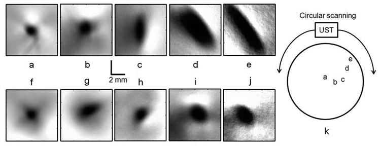
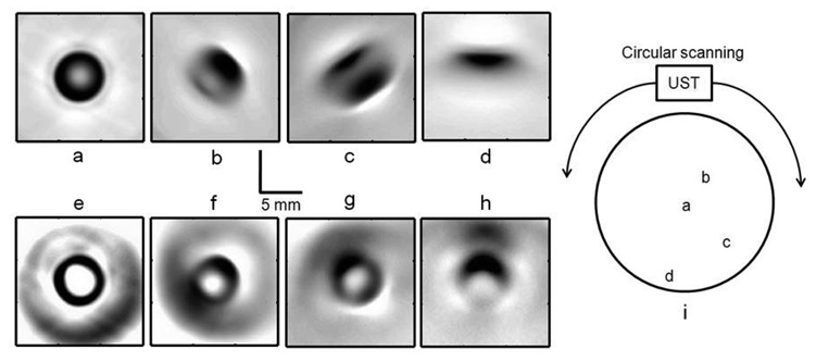
An 18 gauge needle (1 mm diameter) inserted inside a pork fat base was the target object for TAT experiments. The detector was located ~75 mm away from the scanning center. Considering the scanning center to be at (0, 0), other object locations were as follows: (a) (−1.4 mm, 4.0 mm), distance from center ~4.0 mm, distance from detector ~71 mm. (b) (13.5 mm, 1.5 mm), distance from center ~14 mm, distance from detector ~61 mm. (c) (32.0 mm, 2.0 mm), distance from center ~32 mm, distance from detector ~43 mm. (d) (40.5 mm, 28.0 mm), distance from center ~50 mm, distance from detector ~25 mm. (e) (52.5 mm, 36.5 mm), distance from center ~64 mm, distance from detector ~11 mm. Figures 2(a) to 2(e) show the TAT reconstructed images of the needle with a flat detector when the needle was placed at different distances from the scanning center as mentioned before. It is evident that when the object is far from the scanning center, the object is blurred in the reconstructed image and becomes elongated in the tangential direction. Figures 2(f) to 2(j) show the corresponding images when the same target was imaged with a negative lens detector. Figure 2(k) shows the location of the needle inside the scanning region. The radial resolution remains almost the same for all the objects at different locations, as the dependency of radial resolution on the bandwidth and aperture size is spatially invariant. Moreover, the radial resolution is not improved by the use of the negative lens. By contrast, the tangential resolution is poor when the target object is far from the scanning center (Figs. 2(c) to 2(e)), and it is improved significantly with the use of the negative lens (Figs. 2(h) to 2(j)). For objects 3, 4 and 5, we see a more than two fold tangential resolution improvement [Fig. 2(c) vs Fig. 2(h), Fig. 2(d) vs Fig. 2(i), and Fig. 2(e) vs Fig. 2(j)].
FIG. 2.
Reconstructed TAT images, using the flat ultrasonic detector, of a needle (18 gauge, 1 mm in diameter) inserted inside a pork fat base placed at a distance of (a) ~4 mm, (b) ~14 mm, (c) ~32 mm, (d) ~50 mm, and (e) ~64 mm from the scanning center. Corresponding TAT images obtained with the negative lens detector are shown in (f), (g), (h), (i), and (j), respectively. (k) Location of the needle inside the scanner is shown.
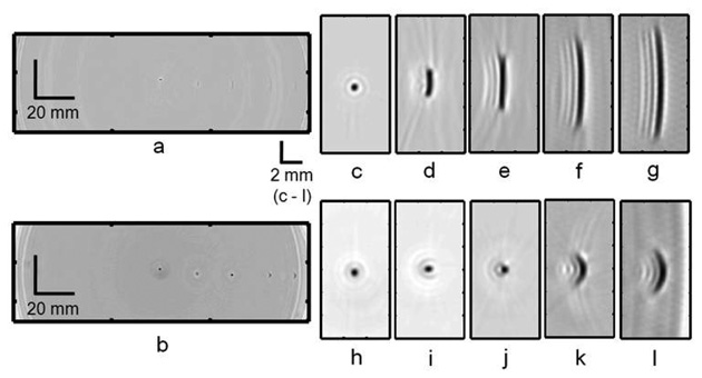
PAT experiments were done using 0.5 mm diameter pencil leads as target objects. Figures 3(a) and 3(b) show the PAT reconstructed image with the flat and negatively focused detectors, respectively, when five pencil leads were placed inside the scanner at different locations. The pencil lead locations were (−0.5 mm, 2.0 mm), (18.5 mm, −0.6 mm), (36.0 mm, −1.2 mm), (55.0 mm, −1.2 mm), and (67.5 mm, −1.4 mm). Figure 3(b) clearly shows all the five objects (two of them near the detector surface are blurred), whereas fig. 3(a) fails to show the target objects except for the one near the scanning center. Figures 3(c) to 3(g) show the close-up reconstructed images of each of the target objects. It is evident that when the object is far from the scanning center the object is blurred and elongated in the tangential direction. Figures 3(h) to 3(l) show the corresponding images acquired with a negative lens detector. Once again as expected, the radial resolution is the same for all the objects (spatial invariance) and it is not improved with the use of a negative lens. But the tangential resolution has spatial dependence (Figs. 3(d) to 3(g)) and it is significantly improved with the use of a negative lens (Figs. 3(i) to 3(l)). For objects 3, 4 and 5 we see a more than three fold tangential resolution improvement [Fig. 3(e) vs Fig. 3(j), Fig. 3(f) vs Fig. 3(k), and Fig. 3(g) vs Fig. 3(l)].
FIG. 3.
PAT images of five 0.5 mm diameter pencil leads placed inside the scanning region at different distances from the scanning center. (a) Reconstructed PAT image using the flat detector. (b) Reconstructed PAT image using the negative lens detector. (c) to (g) Close-up images of all five objects in (a) at distances of ~2 mm, ~19 mm, ~36 mm, ~55 mm, and ~67 mm from the scanning center, respectively. (h) to (l) Corresponding close-up images obtained with the negative lens detector.
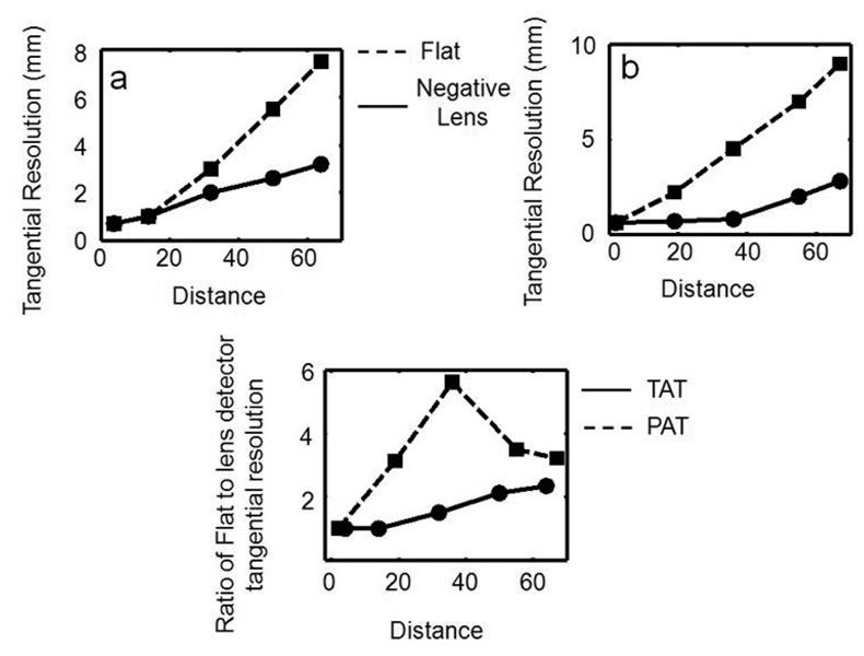
Figures 4(a) and 4(b) show the tangential resolution versus the distance of the target object from the scanning center for TAT and PAT, respectively. Figure 4(c) shows the ratio of the tangential resolution acquired with the flat detector to that acquired with the negative lens detector as a function of the distance from the scanning center. We can see a more than two fold tangential resolution improvement for both TAT and PAT. We observed greater than three fold tangential resolution improvement in PAT when the object is ~20 mm away from the scanning center. Overall greater than two fold tangential resolution improvement is observed for both TAT and PAT, far from the scanning center.
FIG. 4.
Tangential resolution versus distance of the target object from the scanning center. (a) TAT. (b) PAT. (c) Ratio of the tangential resolution of the flat detector to the negative lens detector as a function of the distance from the scanning center.
In the next step, we demonstrate how the type of transducer used for imaging affected the shape of the target object in the reconstructed image. To do so, a LDPE (low density polyethylene) tube (~1 cc volume, inner diameter ~6 mm) filled with salt water (salt was added to increase the TAT signal strength) was placed at different locations, and TAT images were taken using both the flat and negative lens detectors. The tube locations were (a) (1.0 mm, −1.5 mm), (b) (17.5 mm, 15.5 mm), (c) (21.0 mm, −33.0 mm), and (d) (−2.0 mm, −48.5 mm). Figures 5(a) to 5(d) show the TAT reconstructed cross-sectional images of the tube placed at different locations in the scanning region. When the object is near the scanning center we can clearly see the circular shape of the tube’s cross-section [Fig. 5(a)], but when the target is located increasingly further from the scanning center, the object loses its shape in the reconstructed image [Fig. 5(b), 5(c) and 5(d)]. Figures 5(e) to 5(h) show the corresponding images when the negative lens detector was used to image. All clearly show the circular boundary of the target object, but the corresponding images acquired with the flat detector fail to do so, except for the object near the scanning center. Figure 5(i) shows the location of the tube inside the scanning region.
FIG. 5.
Reconstructed cross-sectional TAT images, using the flat ultrasonic detector, of a LDPE tube (~1 cc volume, inner diameter ~6 mm) filled with salt water placed at distances of (a) ~2 mm, (b) ~23 mm, (c) ~39 mm, and (d) ~49 mm from the scanning center, respectively. Corresponding TAT images obtained with the negative lens detector are shown in (e), (f), (g), and (h), respectively. (i) Location of the tube inside the scanner is shown.
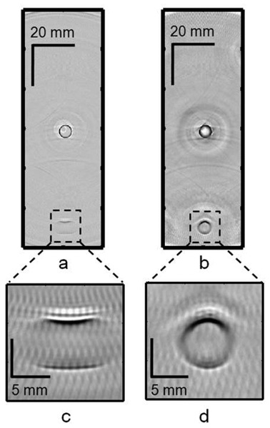
For PAT, two LDPE tubes filled with diluted India ink solution were placed at different locations in the scanner. Figures 6(a) and 6(b) show the PAT reconstructed cross-sectional images of two tubes, one placed near the scanning center and the other placed at a distance of ~50 mm from the scanning center, with the flat and negative lens detectors, respectively. The tube locations were (~0, ~0), and (0.5 mm, −49.3 mm). For the tube near the scanning center, we can clearly see the circular shape of the cross-section using both detectors, but as the target object moves further from the scanning center it loses its shape when the flat detector was used. Figures 6(c) and 6(d) show close-up images of the tube placed at ~50 mm from the scanning center, acquired with the flat and negative lens detectors, respectively. Figure 6(d) clearly shows the circular shape of the object, whereas Fig. 6(c) fails to show the actual shape of the target object.
FIG. 6.
Reconstructed cross-sectional PAT images of two LDPE tubes (~1 cc volume, inner diameter ~6 mm) filled with diluted India ink, one placed near the scanning center and the other at a distance of ~50 mm from the scanning center. (a) Image using the flat detector. (b) Image using the negative lens detector. (c) Close-up image of the tube at ~50 mm from the scanning center using the flat detector. (d) Close-up image of the tube at ~50 mm from the scanning center using the negative lens detector.
The artifacts seen in the images could be due to the quality of the lens fabrication and to imperfections in the glue film between the lens and the detector surface (air bubbles could be trapped in the film). A better lens quality and a bubble free interface between the detector surface and the lens are probably the best ways to get rid of the artifacts in the images. There is also a loss of signal due to the absorption of ultrasound inside the acrylic lens and another loss due to impedance mismatch between the acoustic coupling mineral oil and the acrylic lens. In addition, the reverberation of sound trapped inside the lens could also affect the reconstructed images. Some of these issues could be resolved if instead of using a negative lens we could curve the piezo material used for ultrasonic detection itself to a convex shape. In that way we could get rid of the sound absorption inside the lens material and also the signal loss due to impedance mismatch. In the future, we will be working in this direction to validate the concept.
Conclusions
We observed more than two fold improvement in tangential resolution in both TAT and PAT with the use of a negative lens detector, compared to a flat detector. The increase in acceptance angle enabled us to image a larger scanning area, which is especially useful for breast screening. The same concept can be extended to other tomographic imaging systems where a large imaging area is needed and flat transducers are used as detectors to receive signals. We also showed that a negative lens detector preserves the object shape in the reconstructed images, even when the target is far from the scanning center or close to the detector surface. Such shape preservation could be important in the accurate diagnosis and treatment of tumors.
Acknowledgments
This work was supported by National Institutes of Health grants R01 EB000712 and R01 NS046214. L.W. has a financial interest in Endra, Inc., which however did not support this work. We would also like to thank Dr. Changhui Li for his assistance with the accurate reconstruction algorithm used for TAT and PAT image reconstruction.
References
- 1.Wang LHV, Zhao XM, Sun HT, Ku G. Microwave-induced acoustic imaging of biological tissues. Review of Scientific Instruments. 1999;70(9):3744–3748. [Google Scholar]
- 2.Kruger RA, Miller KD, Reynolds HE, Kiser WL, Reinecke DR, Kruger GA. Breast cancer in vivo: Contrast enhancement with thermoacoustic CT at 434 MHz - Feasibility study. Radiology. 2000;216:279–283. doi: 10.1148/radiology.216.1.r00jl30279. [DOI] [PubMed] [Google Scholar]
- 3.Ku G, Fornage BD, Jin X, Xu MH, Hunt KK, Wang LHV. Thermoacoustic and photoacoustic tomography of thick biological tissues toward breast imaging. Technology in Cancer Research & Treatment. 2005;4(5):559–565. doi: 10.1177/153303460500400509. [DOI] [PubMed] [Google Scholar]
- 4.Xu MH, Wang LHV. Pulsed-microwave-induced thermoacoustic tomography: Filtered backprojection in a circular measurement configuration. Medical Physics. 2002;29(8):1661–1669. doi: 10.1118/1.1493778. [DOI] [PubMed] [Google Scholar]
- 5.Ku G, Wang LHV. Deeply penetrating photoacoustic tomography in biological tissues enhanced with an optical contrast agent. Optics Letters. 2005;30(5):507–509. doi: 10.1364/ol.30.000507. [DOI] [PubMed] [Google Scholar]
- 6.Kruger RA, Liu PY, Fang YR, Appledorn CR. Photoacoustic Ultrasound (Paus) - Reconstruction Tomography. Medical Physics. 1995;22(10):1605–1609. doi: 10.1118/1.597429. [DOI] [PubMed] [Google Scholar]
- 7.Kruger RA, Kopecky KK, Aisen AM, Reinecke DR, Kruger GA, Kiser WL. Thermoacoustic CT with radio waves: A medical imaging paradigm. Radiology. 1999;211(1):275–278. doi: 10.1148/radiology.211.1.r99ap05275. [DOI] [PubMed] [Google Scholar]
- 8.Kruger RA, Reinecke DR, Kruger GA. Thermoacoustic computed tomography-technical considerations. Medical Physics. 1999;26(9):1832–1837. doi: 10.1118/1.598688. [DOI] [PubMed] [Google Scholar]
- 9.Ku G, Wang LHV. Scanning thermoacoustic tomography in biological tissue. Medical Physics. 2000;27(5):1195–1202. doi: 10.1118/1.598984. [DOI] [PubMed] [Google Scholar]
- 10.Ku G, Wang LHV. Scanning microwave-induced thermoacoustic tomography: Signal, resolution, and contrast. Medical Physics. 2001;28(1):4–10. doi: 10.1118/1.1333409. [DOI] [PubMed] [Google Scholar]
- 11.Kruger RA, Kiser WL., Jr Thermoacoustic CT of the Breast: Pilot Study Observations. Proc. SPIE. 2001;4256:1–5. [Google Scholar]
- 12.Kruger RA, Stantz K, Kiser WL., Jr Thermoacoustic CT of the Breast. Proc. SPIE. 2002;4682:521–525. [Google Scholar]
- 13.Wang XD, Pang YJ, Ku G, Xie XY, Stoica G, Wang LHV. Noninvasive laser-induced photoacoustic tomography for structural and functional in vivo imaging of the brain. Nature Biotechnology. 2003;21(7):803–806. doi: 10.1038/nbt839. [DOI] [PubMed] [Google Scholar]
- 14.Ku G, Wang XD, Stoica G, Wang LHV. Multiple-bandwidth photoacoustic tomography. Physics in Medicine and Biology. 2004;49(7):1329–1338. doi: 10.1088/0031-9155/49/7/018. [DOI] [PubMed] [Google Scholar]
- 15.Ku G, Wang XD, Xie XY, Stoica G, Wang LHV. Imaging of tumor angiogenesis in rat brains in vivo by photoacoustic tomography. Applied Optics. 2005;44(5):770–775. doi: 10.1364/ao.44.000770. [DOI] [PubMed] [Google Scholar]
- 16.Oraevsky AA, Savateeva EV, Solomatin SV, Karabutov AA, Andreev VG, Gatalica Z, Khamapirad T, Henrichs PM. Optoacoustic Imaging of Blood for Visualization and Diagnostics of Breast Cancer. In: Oraevsky AA, editor. Biomedical Optoacoustics III. Vol. 4618. 2002. pp. 81–94. [Google Scholar]
- 17.Wang XD, Pang YJ, Ku G, Stoica G, Wang LHV. Three-dimensional laser-induced photoacoustic tomography of mouse brain with the skin and skull intact. Optics Letters. 2003;28(19):1739–1741. doi: 10.1364/ol.28.001739. [DOI] [PubMed] [Google Scholar]
- 18.Xu MH, Wang LHV. Time-domain reconstruction for thermoacoustic tomography in a spherical geometry. IEEE Transactions on Medical Imaging. 2002;21(7):814–822. doi: 10.1109/TMI.2002.801176. [DOI] [PubMed] [Google Scholar]
- 19.Xu MH, Wang LHV. Photoacoustic imaging in biomedicine. Review of Scientific Instruments. 2006;77(4):1–22. [Google Scholar]
- 20.Xu MH, Wang LHV. Analytic explanation of spatial resolution related to bandwidth and detector aperture size in thermoacoustic or photoacoustic reconstruction. Physical Review E. 2003;67(5):056605. doi: 10.1103/PhysRevE.67.056605. [DOI] [PubMed] [Google Scholar]
- 21.Li CH, Ku G, Wang LHV. Negative lens concept for photoacoustic tomography. Physical Review E. 2008;78(2):021901. doi: 10.1103/PhysRevE.78.021901. [DOI] [PMC free article] [PubMed] [Google Scholar]
- 22.Pramanik M, Ku G, Li CH, Wang LHV. Design and evaluation of a novel breast cancer detection system combining both thermoacoustic (TA) and photoacoustic (PA) tomography. Medical Physics. 2008;35(6):2218–2223. doi: 10.1118/1.2911157. [DOI] [PMC free article] [PubMed] [Google Scholar]
- 23.IEEE Std C95.1. Edition 1999. IEEE standard for safety levels with respect to human exposure to radio frequency electromagnetic fields 3 kHz to 300 GHz. [Google Scholar]
- 24.Laser Institute of America, American National Standard for Safe Use of Lasers ANSI Z136.1-2000. New York, NY: American National Standards Institute, Inc.; 2000. [Google Scholar]
- 25.Xu Y, Feng DZ, Wang LHV. Exact frequency-domain reconstruction for thermoacoustic tomography - I: Planar geometry. IEEE Transactions on Medical Imaging. 2002;21(7):823–828. doi: 10.1109/tmi.2002.801172. [DOI] [PubMed] [Google Scholar]
- 26.Xu Y, Xu MH, Wang LHV. Exact frequency-domain reconstruction for thermoacoustic tomography - II: Cylindrical geometry. IEEE Transactions on Medical Imaging. 2002;21(7):829–833. doi: 10.1109/TMI.2002.801171. [DOI] [PubMed] [Google Scholar]


