Abstract
The prospects of gene therapy have generated unprecedented interest in the properties and structures of complexes of nucleic acids (NAs) with cationic liposomes (CLs), which are used as nonviral NA carriers in worldwide clinical trials. An improved understanding of the mechanisms of action of CL–NA complexes is required to enable their widespread therapeutic use. In prior studies of CL-mediated DNA delivery, membrane charge density (σM) was identified as a key parameter for transfection efficiency (TE) of lamellar (LαC) CL–DNA complexes. TE of CL–DNA complexes containing cationic lipids with headgroup valencies from 1+ to 5+ follows a universal bell-shaped curve as a function of σM. As we report here, the TE of CL–DNA complexes containing new multivalent lipids with dendritic headgroups (DLs) strongly deviates from this curve at high σM. We have investigated four DLs, MVLG2 (4+), MVLG3 (8+), MVLBisG1 (8+) and MVLBisG2 (16+), in mixtures with neutral 1,2-dioleoyl-sn-glycerophosphatidyl-choline (DOPC). To understand the TE behavior, we have performed X-ray diffraction (XRD), optical microscopy and cryo-TEM studies of the DL/DOPC mixtures and their DNA complexes. XRD reveals a complex phase behavior of DL–DNA complexes which strongly depends on the headgroup charge. MVLG2(4+)/DOPC–DNA complexes exhibit the lamellar phase at all molar fractions of DL, ΦDL. In stark contrast, MVLBisG2(16+)/DOPC–DNA complexes remain lamellar only for ΦDL ≤ 0.2. In a narrow regime around ΦDL = 0.25, the hexagonal phase HIC, consisting of a hexagonal lattice of cylindrical lipid micelles and a DNA honeycomb lattice, is formed. At ΦDL > 0.3, XRD suggests formation of a distorted HIC phase. For ΦDL ≥ 0.5 under high salt conditions, this phase coexists with a bundle phase of DNA condensed by the depletion-attraction effect of DL micelles. The transitions at high σM from the lamellar phase to the new hexagonal phases of DL–DNA complexes coincide with the deviation from the universal TE behavior of lamellar complexes. The observed high TE, which is independent of σM, strongly suggests a novel mechanism of action for these DL–DNA complex phases.
Keywords: cationic lipids, cationic liposome–DNA complexes, non-viral gene delivery, transfection, lipoplex
Introduction
Gene therapy holds great promise for future medical applications. In fact, numerous clinical trials in this field are currently ongoing, targeting cancers, inherited diseases, and many other disorders with this novel medical approach.1–3 Thus, substantial research efforts are directed towards developing and fundamentally understanding DNA carriers (vectors). These include engineered viruses and synthetic vectors, where the negatively charged DNA is complexed with cationic liposomes (CLs)4–10 or cationic polyelectrolytes.11 The advantages of synthetic vectors include facile and variable preparation and absence of immunogenic protein components. Indeed, nearly one quarter of open clinical trials use nonviral methods, primarily either naked DNA or lipofection-based methods.1,3 Synthetic methods do not suffer from the size limitations of viral vectors, which are ultimately given by the capsid size and prohibit delivering human genes and regulatory sequences extending over hundreds of thousands of DNA base pairs.12 However, for nonviral vectors to become widely useful for therapeutic purposes, their efficiency needs to be improved.4–10 Transfection efficiency (TE), which is a measure of the successful transfer and expression of foreign DNA, is the predominant performance characteristic for gene delivery vectors. Currently, development of CL vectors and improvement of their TE is primarily driven by empirical optimization of formulations rather than systematic studies of the relevant parameters of the ideal CL composition.13 As a case in point, TE often is only measured for a few compositions of newly reported CLs to assess their suitability as DNA vectors,14–17 which may result in the optimum composition being overlooked.
A better understanding of the mechanisms of action of CL–NA complexes and the parameters affecting them is required to rationally improve their TE. The internal structure of the complexes can directly determine the mechanism of transfection.10 To date, three self-assembled structures of CL–DNA complexes have been discovered. They are shown schematically in Figure 1: the prevalent lamellar (LαC) phase which consists of lipid bilayers alternating with the layers of DNA; the inverted hexagonal (HIIC) phase; and the recently discovered hexagonal (HIC) phase.18–20
Figure 1.
Schematic depictions of the internal nanostructure of the three previously describes phases of CL–DNA complexes. (A) Structure of the lamellar LαC phase of CL–DNA complexes with alternating lipid bilayers–DNA monolayers.20 (B) Structure of the inverted hexagonal HIIC phase of CL–DNA complexes, comprised of DNA inserted within inverse lipid tubules, which are arranged on a hexagonal lattice.19 (C) Structure of the hexagonal HIC phase of CL–DNA complexes, where the large dendritic cationic lipid headgroup leads to the formation of rod-like lipid micelles arranged on a hexagonal lattice with DNA inserted within the interstices with honeycomb symmetry.18 Reprinted in part with permission from18,19. HIC phase images © 2006 American Chemical Society.
There are many barriers to successful gene delivery, ranging from serum stability to endosomal release and delivery to the nucleus.10,21 Physico-chemical parameters of CL–DNA complexes often strongly affect their ability to overcome these barriers. Two examples of key parameters which impact the TE of CL–DNA complexes are the membrane charge density, σM, of the cationic lipid membranes and the cationic lipid to DNA charge ratio, ρchg.22,23 Ahmad et al. recently explored the structure–function relationships for CL–DNA complexes spanning a wide range of σM by using new multivalent lipids with headgroup valencies ranging from 2+ to 5+22,24. The TE of these lamellar CL–DNA complexes was found to follow a universal bell-shaped curve as a function of σM. This identified an optimal regime (where TE reaches its maximum) at a specific, intermediate σM where a balance is struck between efficient endosomal escape (via activated fusion of the cationic membranes of the CL–DNA complex and the anionic membranes of the endosome) and release of DNA from the highly charged CL membranes in the cytoplasm.22 To investigate even higher values of σM, a further increase in headgroup valency is required.
In this paper, we report detailed investigations of the DNA complexes of new multivalent lipids with dendritic headgroups (DLs). Dendrimers are monodisperse, highly branched spherical molecules.25 They are typically assembled by adding AB2 building blocks to a central core, thus yielding sequential “generations” of increasing size and endgroup number. Cationic dendrimers have also been studied for gene delivery applications .26–29 The generation, and therefore size and charge, of the dendrimers governs their complexation with DNA.30 In particular, polypropylene imine dendrimers form distinct columnar phases with DNA, depending on the generation of the dendrimer.31
The DLs investigated in this work are based on ornithine as the AB2 building block.18,32 Their headgroup valency ranges from 4+ to 16+, allowing for a systematic study of the effect of large headgroup charge. By mixing the lipids with varying amounts of the neutral lipid 1,2-dioleyl-sn-glycerophosphatidyl-choline (DOPC), liposomes with a broad range of σM up to 40×10−3 e/Å2 have been prepared. The TE of DL–DNA complexes containing these liposomes significantly deviates from the universal TE curve at high σM, never dropping below the optimum efficiency.
In order to understand this unexpected transfection behavior, we have performed X-ray diffraction (XRD) and zeta potential experiments on DL/DOPC–DNA complexes. We have also studied the phase behavior of MVLBisG2(16+)/DOPC lipid mixtures in absence of DNA with differential interference contrast (DIC) microscopy, fluorescence microscopy and cryo-TEM. XRD reveals a complex phase behavior of DL–DNA complexes which strongly depends on the headgroup charge. MVLG2(4+)/DOPC–DNA complexes exhibit the lamellar phase at all molar fractions of DL (ΦDL). In stark contrast, MVLBisG2(16+)/DOPC–DNA complexes remain lamellar only for ΦDL ≤ 0.2. In a narrow regime around ΦDL = 0.25, the hexagonal phase HIC, consisting of a hexagonal lattice of cylindrical lipid micelles and a DNA honeycomb lattice, is formed. At ΦDL > 0.3, XRD suggests formation of a distorted HIC phase. For ΦDL ≥ 0.5 under high salt conditions, this phase coexists with a bundle phase of DNA condensed by the depletion-attraction effect of DL micelles. MVLG3(8+)/DOPC–DNA complexes and MVLBisG1(8+)/DOPC complexes remain lamellar for ΦDL ≤ 0.5, when a phase transition towards the distorted hexagonal phase occurs. The transitions at high σM from the lamellar phase to the new hexagonal phases of DL–DNA complexes coincide with the deviation from the universal TE behavior of lamellar complexes. The observed high TE, which is independent of σM, strongly suggests a novel mechanism of action for these DL–DNA complex phases.
Materials and Methods
Lipid Solutions
DLs were synthesized as reported elsewhere.18,32 Stock solutions of DLs were prepared in chloroform/methanol (9/1, v/v). 1,2-dioleoyl-sn-glycero-3-phosphatidylcholine (DOPC) was purchased as a solution in chloroform from Avanti Polar Lipids. These lipid solutions were combined at the desired ratio of lipids and dried, first by a stream of nitrogen and subsequently in a vacuum for 8 to 12 hours. To the residue, high resistivity (18.2 MΩ) water was added and the mixture was incubated at 37 °C for at least 12 hours to give solutions of a final concentration of 30 mM for X-ray samples (15 mM for MVLBG2). For transfection and optical microscopy, aqueous solutions were prepared at 0.6 mM. Lipid mixtures containing higher molar fractions of DOPC formed opaque suspensions, which were sonicated to clarity and filtered through 0.2 µm pore Teflon filters. The lipid solutions were stored at 4 °C until use.
Zeta-Potential
A Zeta-Meter 3.0 instrument (Zeta-Meter, Inc.) was used to obtain the ζ-potential of lipid–DNA complexes. Each sample contained 0.6 mg highly polymerized calf thymus DNA (HPCT DNA, from USB) and the appropriate amount of DL-DOPC liposomes in a total volume of 20 mL. Measurements were conducted at an applied voltage of 75 mV.
Optical Microscopy
A Nikon Diaphot 300 inverted microscope equipped for epifluorescence and differential interference contrast (DIC) and a SensiCamQE High Speed digital camera were used. A Nikon Optiphot-2Pol microscope was used for polarized microscopy. Samples were first checked for birefringence by polarized microscopy, and then studied by DIC microscopy.
Cryo-TEM
The specimens were preserved in a layer of vitreous ice suspended over a holey carbon substrate. The holey carbon films consist of a thin layer of pure carbon fenestrated by 2 µm holes spaced 4 µm apart and suspended over 400 mesh copper grids.33 The grids were cleaned prior to vitrification with a Solarus plasma cleaner (Gatan Inc.) using a 25% O2, 75% Ar mixture. The concentration of the sample solution was varied depending on the kind of the sample. It typically equalled 5–10 mg/mL for aqueous lipid solutions and 30 mg/mL for the micellar lipid solutions. Samples were vitrified by plunge freezing into liquid ethane using a Vitrobot (FEI Co.). Microscopy was carried out using a Tecnai F20 (FEI Co.) TEM at 120 keV with magnifications ranging from 29 000 to 280 000. Images were acquired at an underfocus of ~2.5 µm to a slow scan CCD camera (TVIPS GmbH) using the Leginon software system.34
Transfection
Mouse fibroblast cells L-cells (ATCC number: CCL-1) were a gift from C. Samuel (UCSB). Cells were cultured at 37 °C in supplemented cell medium (Dulbecco's Modified Eagle's Medium (DMEM) with 1% penicillin-streptomycin and 5% fetal bovine serum, v/v; from Gibco BRL) in an atmosphere containing 5% CO2 and reseeded approximately every 72 hours to maintain sub-confluency. The day before the transfection experiment, cells were seeded in 24-well plates (at 80 000 cells per well). At the time of transfection, the cells were approximately 70% confluent. Luciferase plasmid DNA (pGL3 Control Vector, Promega) was prepared using a Qiagen Giga Kit (Qiagen). For each well, 0.4 µg of luciferase plasmid DNA was used. Lipid solution (0.6 mM) was added to the DNA and the mixture was diluted to a final volume of 0.1 mL with non-supplemented DMEM. This mixture was incubated for 15 minutes. The cells were incubated with this solution for six hours, rinsed three times with phosphate-buffered saline (PBS, Invitrogen) and incubated with supplemented cell medium for an additional 24 hours. Luciferase gene expression was measured with the Luciferase Assay System (Promega) and light output readings were taken on a Berthold AutoLumat luminometer. The average of four experiments is reported per data point, with the standard deviation plotted as the error bars. Transfection efficiency, measured in relative light units (RLU), was normalized to the weight of total cellular protein determined using Bio-Rad Protein Assay Dye Reagent (Bio-Rad). Absolute values for TE tend to vary over time, e.g., with increasing passage number of the cells. Thus, all experiments reported were performed on the same day or in close temporal proximity per set to allow direct comparison of the data sets.
Small-angle X-ray Scattering
The appropriate volume of lipid solution (see above) was added to a solution of 0.2 mg of HPCT DNA in 40 µL of water, to yield a charge ratio (ρchg) of 2.8. Unless otherwise noted, a volume of DMEM equal to that of the DNA and liposome mixture was added. Samples were centrifuged for 3 hours at 19 000 RPM in a Sorvall SS34 rotor and stored at 4 °C for at least three days to reach equilibrium. Typically, the CL–DNA complexes formed a white precipitate and these pellets were transferred to 1.5 mm quartz capillaries and flame sealed. X-ray scattering data was collected at beamline 4-2 of the Stanford Synchrotron Radiation Laboratory (SSRL). The beam energy was 8.98 keV and the distance of the sample to the detector was 1 m. A charge-coupled device-based area detector (MarCCD165, Mar USA, Evanston, IL) was used. Silver behenate was used as a calibration standard. Scans were performed for 5 min. No radiation damage occurred in the samples during this time (data not shown). The acquired radial scans were integrated over 360° to obtain plots of scattering intensity versus momentum transfer.
Results and Discussion
New Multivalent Cationic Lipids with Dendritic Headgroups
A main motivation for the synthesis of the highly charged lipids with dendritic headgroups (DLs) investigated in this work was to study the transfection behavior of CL–DNA complexes at very high membrane charge densities σM. In prior work, Ahmad et al. identified σM as a universal parameter governing the TE of lamellar CL–DNA complexes.22 Lipids in that study ranged in their headgroup valency from 2+ to 5+. The TE of these lipid mixtures followed a universal bell-shaped curve as a function of σM. The upper limit of σM, corresponding to membranes of pure pentavalent MVL5, was 27.17×10⁻³ e/Å2.
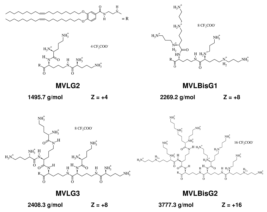
The synthesis and the chemical characterization of the multivalent cationic dendrimer lipids studied in this paper (MVLG2, MVLG3, MVLBisG1, and MVLBisG2) have been previously described by Ewert et al.18,32 The dendritic headgroups of the studied lipids are based on ornithine as an AB2 building block. Figure 2 provides a summary of the chemical structures, molecular weights and valencies at full protonation for the studied DLs. Mixing of these lipids with the neutral lipid 1,2-dioleoyl-sn-glycerophosphatidyl-choline (DOPC) results in liposomes having σM of up to 40×10−3 e/Å2. Space-filling molecular models of the studied DLs, monovalent DOTAP and DOPC are shown in Figure 3. Only very few other lipids with a similar number of charges in the headgroup have been reported to date.35
Figure 2.
Summary of the chemical structures, molecular weights, and maximum charge of the DLs MVLG2, MVLG3, MVLBisG1, and MVLBisG2. The alkyl tails (R) are identical for all four molecules.
Figure 3.
Molecular models of MVLG2, MVLG3, MVLBisG1, MVLBisG2, DOTAP and DOPC.
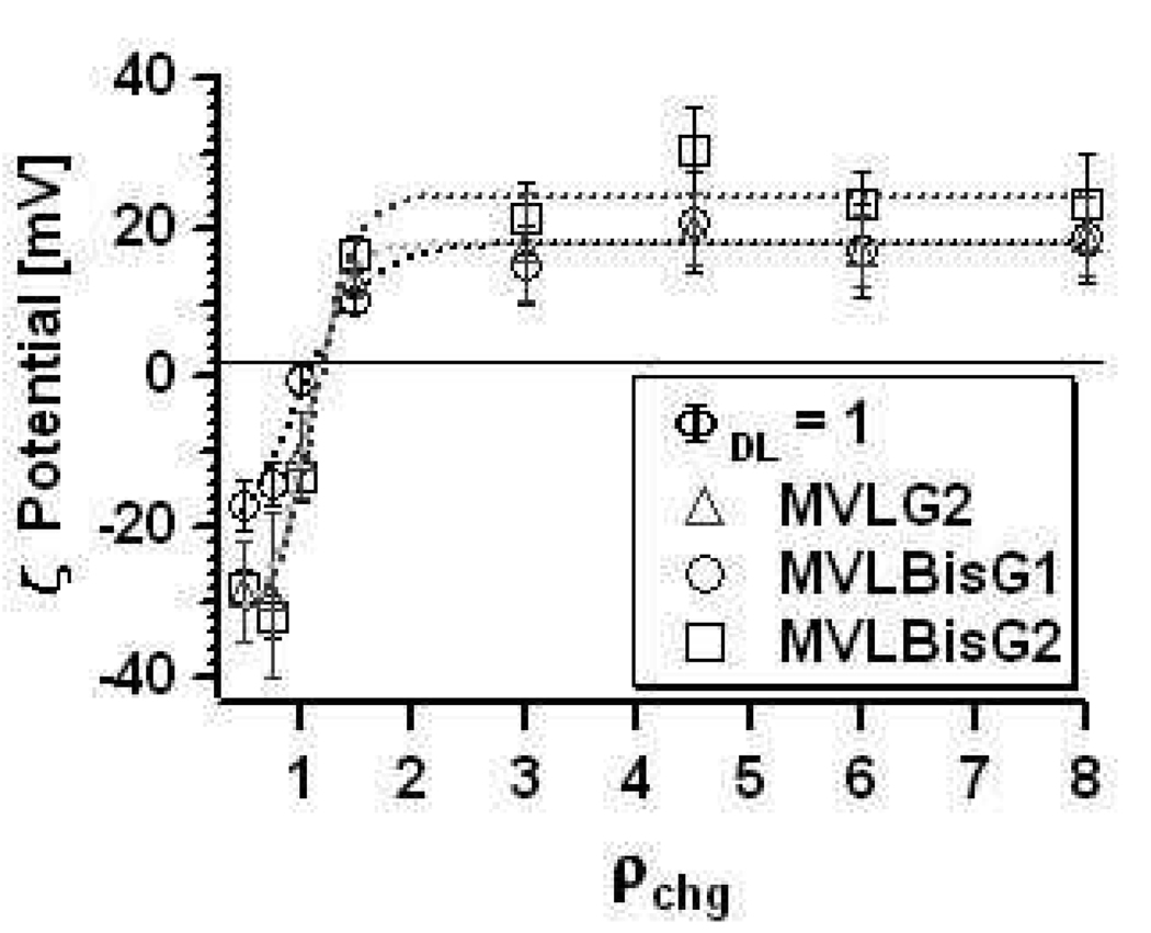
We confirmed the high charge of the DLs by conducting ζ-potential measurements which yield the isoelectric point (IP) of the DL/DOPC–DNA complexes. At the IP, the DL–DNA complexes are neutral, as the charge of the cationic lipid exactly matches the charge of negatively charged DNA. This method also demonstrates the phenomenon of “overcharging” where isoelectric (charge-neutral) CL–DNA complexes incorporate excess DNA or cationic liposomes, leading to overall negatively or positively charged complexes, respectively.36 Figure 4 shows the ζ-potential for DL–DNA complexes containing MVLG2, MVLBisG1, and MVLBisG2 at ΦDL = 1, plotted as a function of the calculated cationic lipid to DNA charge ratio, ρch. This charge ratio was calculated using values for the headgroup charges which were obtained using an ethidium bromide (EtBr) displacement assay.18,32,37 These values of 4.0 ± 0.2 for MVLG2, 7.9 ± 0.3 for MVLG3, 8.0 ± 0.1 for MVLBisG1, and 14.6 ± 0.4 for MVLBisG2 are very close to the charge of the DLs at full protonation and are confirmed by the ζ-potential measurements, as evident from Figure 4. A sigmoidal function fits the data for all three molecules well, yielding the x-intercept (where the ζ-potential = 0) and therefore the experimental charge ratio for the isoelectric point of the DL–DNA complexes. As evident from Table 1, which summarizes the lipid valencies thus determined and the average ζ-potential of the plateau in the cationic excess region, the headgroup charge is essentially independent of ΦDL for all studied DLs.
Figure 4.
Plots of the ζ-potential of DL–DNA complexes (ΦDL = 1) as a function of ρchg. Dotted lines correspond to sigmoidal fits of the data.
Table 1.
Summary of the values obtained for isoelectric point (valency; top entry) and average ζ-potential in the cationic plateau region (bottom entry) for different ΦDL of DL/DOPC–DNA complexes.
| ΦDL | MVLG2 (4+) |
MVLBisG1 (8+) |
MVLBisG2 (16+) |
|---|---|---|---|
| 1 | 4.8 | 8.6 | 16.8 |
| 18 ± 6 mV | 18 ± 6 mV | 24 ± 5 mV | |
| 0.7 | 4.4 | 9.3 | 21.1 |
| 17 ± 5 mV | 16 ± 4 mV | 15 ± 4 mV | |
| 0.3 | 4.0 | 9.9 | 13.3 |
| 13 ± 2 mV | 13 ± 2 mV | 16 ± 5 mV |
Transfection Efficiency of DL–DNA Complexes
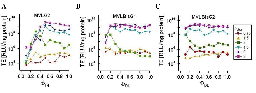
Figure 5 shows a summary of transfection efficiency measurements for DL/DOPC–DNA complexes as a function of ΦDL and ρchg. TE data is not shown for MVLG3 (same valence as MVLBisG1) for clarity, since the trends are similar for the two DLs.
Figure 5.
TE of DL/DOPC–DNA complexes containing (A) MVLG2, (B) MVLBisG1 or (C) MVLBisG2 measured for ρchg = 0.75, 1.5, 3, 4.5, 6, and 8 as a function of ΦDL. TE of all studied DL/DOPC–DNA complexes benefits from ρchg ≥ 4.5.
Figure 5A shows the TE of MVLG2/DOPC–DNA complexes for a range of different ρchg as a function of ΦDL. At low ρchg < 2, TE is very low and independent of ΦDL. The TE is, in fact, comparable to that of the naked DNA (9.6×10⁴ mg/protein). At higher ρchg, TE increases and becomes strongly dependent on ΦDL, reaching its maximum at ΦMVLG2 ≈ 0.5 and dropping again beyond this value. Little change is observed in the curves for values of ρchg ≥ 4.5. As evident from the data in Figures 4B and 4C, the other DLs show a similar behavior as a function of ρchg. This is reminiscent of the behavior seen for DOTAP and multivalent lipids with valencies up to 5+, where TE at the optimal ΦDL increases with ρchg up to a saturation value. Interestingly, this value is higher for the DLs (ρchg ≈ 4.5) then for previously investigated lipids (ρchg ≈ 3).
An unexpected trend is seen for the TE of DL/DOPC–DNA complexes of MVLBisG1 and MVLBisG2 as a function of ΦDL (Figure 5B,C; ρchg ≥ 4.5). TE quickly reaches its maximum, at ΦMVLBisG1 ≈ 0.2 and ΦMVLBisG2 ≈ 0.1, and remains at this high level, independent of the increasing ΦDL and thus σM. To investigate this in more detail, the TE data at two high values of ρchg is plotted as a function of σM in Figure 6.
Figure 6.
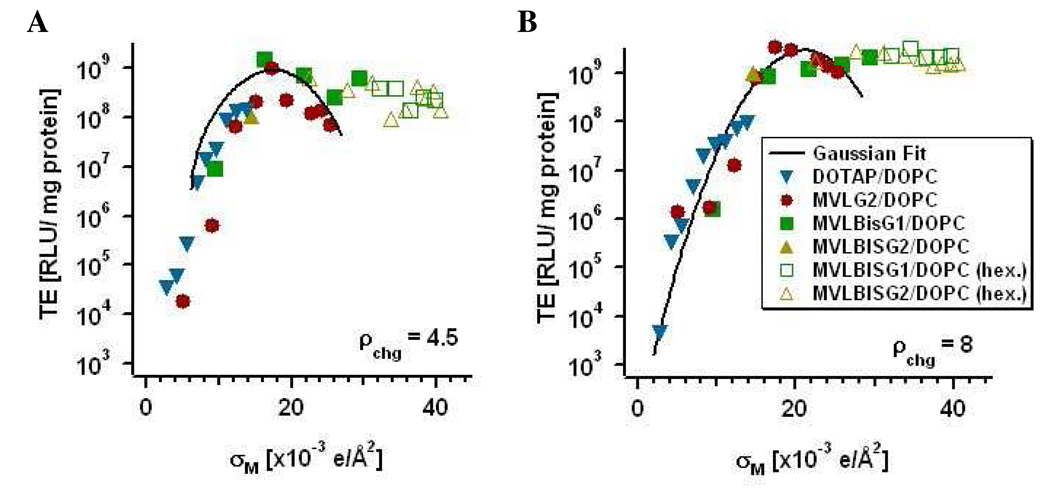
TE of DL/DOPC–DNA complexes containing MVLG2, MVLBisG1 or MVLBisG2 plotted as a function of σM for two different values of ρchg. (A) TE at ρchg = 4.5 and (B) TE at ρchg = 8. The solid line represents the universal TE curve22. The solid symbols represent DL/DOPC–DNA complexes in the lamellar phase, while empty symbols correspond to DL/DOPC–DNA complexes in hexagonal phases.
As mentioned earlier, Ahmad et al. identified σM as a universal parameter controlling the TE of lamellar CL–DNA complexes with σM up to 27.17×10⁻³ e/Å2.22 DL–DNA complexes allow access to values of σM up to 40×10−3 e/Å2, with σM calculated according the following equation:
| (1) |
where Ncl and Nnl are the number of cationic lipids and neutral lipids in the CL–DNA complexes, respectively; r = Acl/Anl is the ratio of the headgroup areas of the cationic and the neutral lipid; σcl = eZ/Acl is the charge density of the cationic lipid of valence Z; and Φnl and Φcl are the molar fractions of the neutral and cationic lipids. The headgroup valencies used were determined using an ethidium bromide intercalation assay32 and confirmed by ζ-potential measurements, as described above. The ratio r (assuming ADOPC = 72 Å2 38), was obtained by fitting the TE of the DLs and DOTAP (Z = r = 1) at low σM to a Gaussian function: TE = TE0 + Aexp(−[(σM − σM*)/w]2), as done for the universal TE curve.22 This yielded values for r of 2.2 for MVLG2, 2.8 for MVLBisG1, and 5.0 for MVLBisG2. These numbers are in good agreement with the relative headgroup areas for multivalent lipids determined in a similar way by Ahmad et al., where, e.g., r = 2.3 for MVL5, a cationic pentavalent lipid.
In Figure 6, plots of the TE of DL/DOPC–DNA complexes as a function of σM are shown for ρchg = 4.5 and ρchg = 8. Also shown are the Gaussian fits, representing the universal TE curves (black solid lines). As noted above, TE of MVLG2/DOPC–DNA complexes exhibits the previously observed dependence on σM and thus closely follows the universal curve. However, the data for both MVLBisG1/DOPC–DNA complexes as well as MVLBisG2/DOPC–DNA complexes deviate strongly from the universal TE curve for σM ≥ 18×10−3 e/Å2, which is close to the maximum of the universal TE curve. Beyond this value of σM, TE of these DL–DNA complexes remains high instead of dropping.
This behavior is reminiscent of the TE of DOTAP/DOPE–DNA complexes, which is independent of σM, albeit at low membrane charge densities. DOTAP/DOPE–DNA complexes exhibit the inverted hexagonal phase at low σM, and their constant, high TE reflects a different mechanism of action by the lamellar and the inverted hexagonal CL–DNA complexes.23 For lamellar CL–DNA complexes, endosomal escape via activated fusion limits TE and strongly depends on σM, whereas the inverted hexagonal phase promotes fusion of the CL–DNA complex membranes with cellular membranes independent of σM and thus the TE of such CL–DNA complexes does not vary with σM.
Structure Determination of DL–DNA Complexes via Small-Angle X-ray Scattering
The prior findings of structure–function relationships for CL–DNA complexes suggest that the constant, high TE of DL–DNA complexes at high σM may be related to their nanoscopic structure. Consequently, we have investigated the structures of the DL–DNA complexes via small-angle X-ray scattering in an effort to find the cause of their unexpected TE behavior.
Structure of MVLG2/DOPC–DNA Complexes
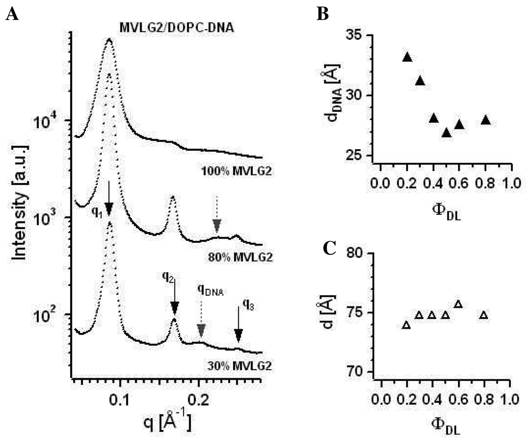
Figure 7A shows X-ray diffraction data collected for MVLG2/DOPC–DNA complexes at three different compositions: ΦMVLG2 = 0.3, 0.8, and 1. These self-assemblies exhibit the lamellar Lαc phase, which is also true for all other molar ratios of MVLG2/DOPC (data not shown). First, second and third order of the lamellar peak are marked by q1, q2, and q3, respectively. The first order of the lamellar peak broadens with increasing ΦMVLG2, suggesting an increasing disorder as well as smaller domain size of the DL–DNA complexes. Grey dashed arrows point to the DNA peak at qDNA. From the X-ray data the lamellar spacing d (d = 2π/q1 = δm + dw, where δm is the membrane thickness and dw is the thickness of the water layer) as well as the spacing between the DNA molecules dDNA (= 2π/qDNA) can be obtained.20
Figure 7.
(A) X-ray diffraction data for MVLG2/DOPC–DNA complexes at ΦMVLG2 = 0.3, 0.8, and 1. First, second and third order of the lamellar peak are marked by q1, q2, and q3, respectively. Grey dashed arrows point to the DNA peak at qDNA. (B) Plot of dDNA as a function of increasing ΦMVLG2. For ΦMVLG2 = 1, no DNA correlation peak is observed. (C) Plot of the intralamellar spacing d of MVLG2/DOPC–DNA complexes as a function of increasing ΦMVLG2.
As shown in Figure 7B which shows the variation of dDNA with ΦMVLG2, dDNA decreases from 33 Å at ΦMVLG2 = 0.1 to 28.1 Å at ΦMVLG2 = 0.8. For ΦMVLG2 = 1, no DNA correlation peak is observed. The measured values of dDNA indicate a very tight packing of DNA molecules within MVLG2/DOPC–DNA complexes even at low σM, considering that while the structural diameter of a DNA molecule is 20 Å, a fully hydrated DNA molecule has an effective diameter of ~25 Å.39 This observation is consistent with previous findings for the multivalent lipids MVL3(3+) and MVL5(5+) by Farago et al., who attributed the tight packing at low σM to a unique DNA locking mechanism involving the multivalent headgroups.40 Figure 7C displays the intralamellar spacing d of MVLG2/DOPC–DNA complexes, which changes only slightly from 74 Å to 76 Å as a function of increasing ΦMVLG2.
Phase Behavior of MVLBisG2/DOPC–DNA Complexes
The hexadecavalent cationic MVLBisG2 is the largest of the studied DLs. The size of its dendritic headgroup leads to a conical molecular shape, resulting in a positive spontaneous membrane curvature. When mixed with cylindrically shaped DOPC, MVLBisG2 exhibits a rich phase diagram as previously found in DIC microscopy and cryo-TEM studies.41 In these studies of the shape evolution of MVLBisG2/DOPC liposomes as a function of ΦMVLBisG2, micelles were found to appear at ΦMVLBisG2 ≈ 0.5, where they coexist with vesicles. At ΦMVLBisG2 ≥ 0.75, the MVLBisG2/DOPC lipid mixture forms only micelles. In the present work, we have investigated the structural properties of MVLBisG2/DOPC–DNA complexes using cryo-TEM in addition to small-angle X-ray scattering.
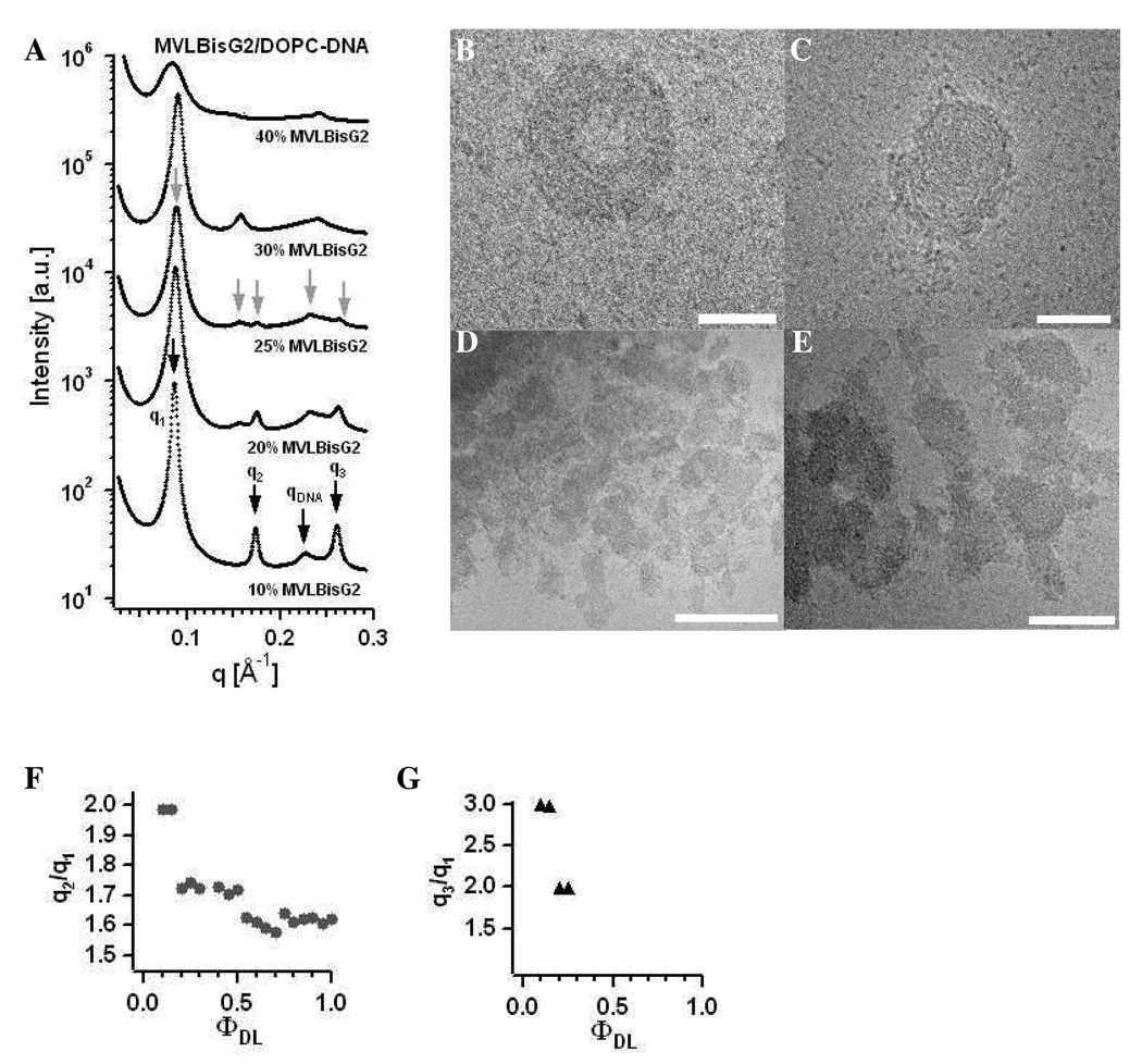
Figure 8A shows X-ray diffraction data for MVLBisG2/DOPC–DNA complexes at ΦMVLBisG2 = 0.1, 0.2, 0.25, 0.3, and 0.4. For ΦMVLBisG2 < 0.2, the lamellar LαC phase is observed. In this regime, the lamellar spacing is constant at d = 73 Å and dDNA changes from 28 Å for ΦMVLBisG2 = 0.1 to 26.4 Å for ΦMVLBisG2 = 0.15. In a narrow interval of ΦMVLBisG2 ≈ 0.25, the novel hexagonal (HIC, see also Figure 1) CL–DNA complex phase is found.18 This phase is comprised of a hexagonally ordered lattice of cylindrical micelles and a surrounding DNA honeycomb lattice. The diffraction peaks for the HIC phase are labeled with gray arrows in Figure 8A, with five orders of diffraction visible. The X-ray scattering data for ΦMVLBisG2 = 0.2 suggests coexistence between the lamellar and the hexagonal phase (note, e.g., the high intensity of the peak at q3 = 2q1) which was confirmed by cryo-TEM for 0.2 ≤ ΦMVLBisG2 ≤ 0.3. Figure 8B–E show examples of morphologies of MVLBisG2/DOPC–DNA complexes found at ΦMVLBisG2 = 0.25. The morphologies shown in Figure 8D,E resemble those seen by others for lamellar CL–DNA complexes, while the structures in Figure 8B,C are reminiscent of toroids of condensed DNA.42,43 Such structures could easily be formed by DL–DNA complexes in the HIC phase. Interestingly, the first order diffraction peak at q = 0.088 Å−1 is identical for the lamellar and the hexagonal phase. This indicates that the lattice dimensions may facilitate the structural transition between them. The lamellar repeat distance d = 2π/q1 is 71.4 Å, while the hexagonal lattice constant a is 82.4 Å (a = 4π/(3)1/2q1).
Figure 8.
(A) X-ray diffraction data for MVLBisG2/DOPC–DNA complexes at ΦDL = 0.1, 0.2, 0.25, 0.3, and 0.4. The diffraction peaks corresponding to the Lαc phase are marked by black arrows, and the diffraction peaks corresponding to the ordered HIC phase are marked by grey arrows. (B–E) Cryo-TEM images of MVLBisG2/DOPC–DNA complexes at ΦDL = 0.25, demonstrating coexistence of the hexagonal phase, shown in B and C, and lamellar phase, shown in D and E. The scale bar represents 50 nm in B and C, 200 nm in D and 100 nm in E. (F) Ratio of the first and second order diffraction peaks, q2/q1, and (G) ratio of the first and third order diffraction peaks, q3/q1, plotted as a function of increasing ΦMVLBisG2.
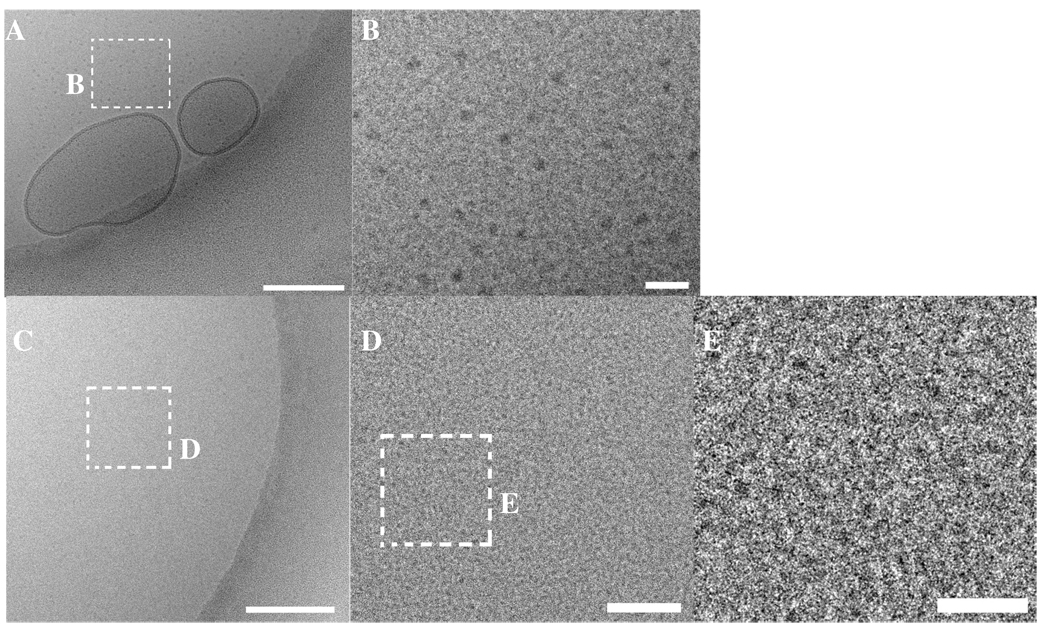
At ΦMVLBisG2 = 0.4, a phase transition to a distorted hexagonal lattice occurs, persisting up to ΦMVLBisG2 = 1. This phase is characterized by broad diffraction peaks with q2/q1 = 1.6. Figure 8F shows the ratio of peak positions q2/q1 as a function of increasing ΦMVLBisG2. Both phase transitions, from lamellar to hexagonal and from hexagonal to distorted hexagonal, can be clearly identified by the changes in q2/q1 from 2 to 1.7 and from 1.7 to 1.6, respectively. Figure 8G plots q3/q1 against ΦMVLBisG2, also visualizing the phase transition from lamellar to hexagonal ordering. MVLBisG2/DOPC–DNA complexes at higher ΦMVLBisG2 did not show any third order diffraction peaks, presumably due to increasing disorder in the lipid–DNA assemblies. The phase transition from the hexagonal phase to the distorted hexagonal phase coincides with the appearance of micelles in the MVLBisG2/DOPC lipid mixture at ΦMVLBisG2 ≈ 0.5,41 suggesting a direct impact of the presence of micelles on the assembly of MVLBisG2/DOPC–DNA complexes. The results of cryo-TEM investigations on mixtures of MVLBisG2 and DOPC in water at ΦMVLBisG2 ≥ 0.5 are shown in Figure 9. The coexistence of micelles and vesicles (closed lipid bilayers) is apparent in Figure 9A,B which shows cryo-TEM images taken at ΦMVLBisG2 = 0.75. Figure 9B displays the enlargement of a part of the image in Figure 9A, showing the micelles in greater detail. Their shape seems to be slightly elongated, possibly discoidal or cylindrical. Figure 9C–E shows cryo-TEM of the MVLBisG2/DOPC lipid mixture at ΦMVLBisG2 = 1. Only micelles and no vesicles were observed at this ΦDL. The higher magnification images (Figure 9D,E) demonstrate that the micelles are spherical with a diameter of ~ 4 nm (of the hydrophobic core).
Figure 9.
(A) Cryo-TEM image of a MVLBisG2/DOPC lipid mixture at ΦDL = 0.75 in the absence of DNA, showing a coexistence of lipid vesicles and micelles. (B) An enlarged inset from A displaying the micelles in greater detail. (C) Cryo-TEM image of a MVLBisG2/DOPC lipid mixture at ΦDL = 1 in the absence of DNA. No vesicles are observed. (D) An enlargement of the area marked in C demonstrates the presence of the micelles (black dots). (E) An inset area from D showing the micelles (black) in greater detail. The scale bar represents 200 nm in A and C, 50 nm in D and 20 nm in B and E.
Figure 10A shows a collection of X-ray diffraction data for DL–DNA complexes in the distorted hexagonal phase at 0.6 ≤ ΦMVLBisG2 ≤ 1. In addition to the peaks from this phase, a common feature in the form of a peak at q = 0.241 Å−1 (marked by a dashed line) is visible, corresponding to a spacing of 25.9 Å. Notably, the position of this peak does not change with ΦMVLBisG2, in contrast to the position of the first order diffraction peak. This indicates that the two features are not part of the same structure. The spacing of 25.9 Å matches that of a tight packing of DNA into condensed bundles. The occurrence of a DNA bundle phase is further consistent with the fact that the spacing of 25.9 Å (dcond) does not vary with ΦMVLBisG2. In addition, the position of the corresponding peak moves towards higher q with increasing ionic strength of the medium, as shown in Figure 10B. TE and X-ray experiments described here were conducted in cell culture medium (DMEM), which contains ≈150 mM monovalent salt. To avoid any artifacts due to the complex composition of DMEM (which also contains small amounts of divalent salts, amino acids, etc.), we prepared MVLBisG2/DOPC–DNA complexes in the presence of varied concentrations of NaCl. Figure 10C shows that dcond decreases with increasing ionic strength of the medium, demonstrating that an increased screening of the electrostatic interaction results in closer packing of DNA. It is noteworthy that MVLBisG2/DOPC–DNA complexes prepared in water (Figure 10B) do not show any discernible diffraction peaks, thus highlighting the key role of salt in the self-assembling process of MVLBisG2/DOPC–DNA complexes and in formation of the DNA bundles. The salt-induced screening of the electrostatic repulsion between the negatively charged DNA molecules is required in order to closely pack DNA molecules. The driving force for the DNA bundling is a depletion–attraction force generated by the presence of lipid micelles. In fact, as ΦMVLBisG2 increases, there is an increase in the intensity of the peak at q = 0.241 Å−1 and a decrease in the intensity of the peak at q1, which is consistent with the fact that the number of micelles increases with increasing ΦMVLBisG2, as reported previously.41 Further evidence for the existence of a depletion–attraction force due to lipid micelles is depicted in Figure 10D, which shows aggregates of vesicles in solutions of the MVLBisG2/DOPC lipid mixture at ΦMVLBisG2 = 0.5 in water, where vesicles and micelles coexist. Despite the electrostatic repulsion of the cationic membranes, the image shows an effective attractive interaction between vesicles, caused by the micelle-mediated depletion–attraction.
Figure 10.
(A) X-ray diffraction data for MVLBisG2/DOPC–DNA complexes at ΦDL = 0.6, 0.7, 0.8, 0.9, and 1. (B) X-ray diffraction data for MVLBisG2/DOPC–DNA complexes at ΦDL = 0.7 under different salt conditions. (C) Spacing d between the DNA molecules within the DNA bundles as a function of NaCl concentration. (D) DIC image of a MVLBisG2/DOPC lipid mixture in water at ΦDL = 0.5 showing aggregates of vesicles due to the depletion–attraction mediated by the lipid micelles.
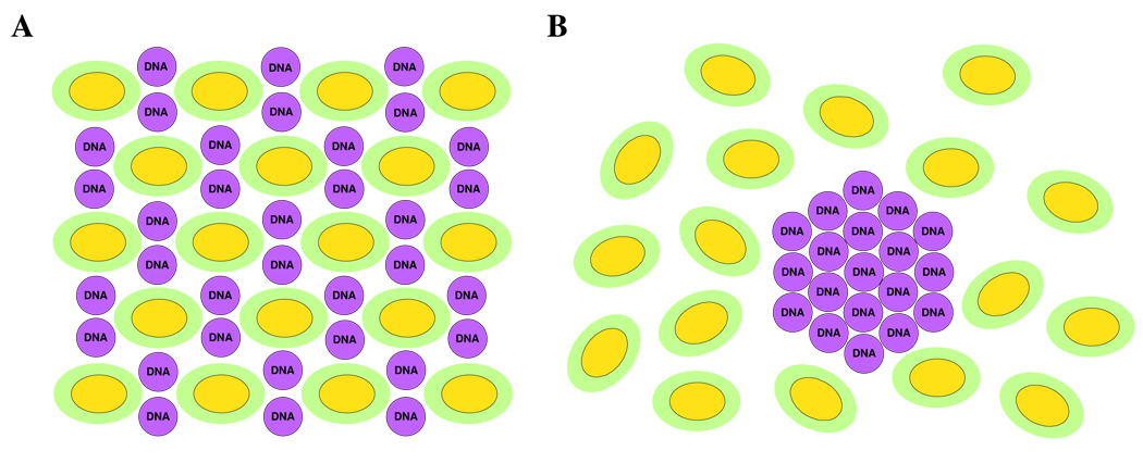
Figure 11 shows schematic depictions of the structures proposed above. A cross section of a distorted hexagonal lattice is shown in Figure 11A, displaying lipid micelles of an elliptical cross section and DNA molecules localized in the interstitial space. The distortion of the lattice is likely caused by the asymmetry in the micellar shape. As our X-ray diffraction data shows, the distortion increases with increasing ΦMVLBisG2, suggesting that the shape of the micelles in the DL–DNA complexes changes. With increasing ΦMVLBisG2, the overall size of the micelles is expected to decrease because MVLBisG2 molecules favor a positive membrane curvature. Therefore, it is plausible that the lipid cylinders in the HIC phase become shorter with increasing ΦMVLBisG2 until they eventually turn into quasi-spherical micelles. This is consistent with our cryo-TEM studies (cf. Figure 9) as well as X-ray diffraction data for ΦMVLBisG2 = 1 (cf. Figure 10A). Figure 11B shows a schematic of the DNA bundle phase observed at ΦMVLBisG2 > 0.5, which is formed by the interplay of the salt-induced screening of the electrostatic interactions and the depletion–attraction caused by the lipid micelles. While depletion–attraction has previously been reported for like-charged or neutral objects, the screening of the electrostatic interactions enables this effect to be observed also between DNA and the oppositely charged lipid micelles, for which the electrostatic interactions are attractive. The presence of salt not only facilitates bundling of DNA by reducing the electrostatic repulsion between DNA molecules. It also reduces the 16 electrostatic attraction between positively charged micelles and negatively charged DNA (Figure 11A) to a level where it is less than the entropy gained by the micelles upon confining the DNA into bundles (Figure 11B).
Figure 11.
(A) Schematics of the molecular structure of DL–DNA complexes assembled in slightly disordered HIC; (B) DNA bundles surrounded by a cloud of micelles (lipid heads in green, lipid tails in yellow). The depletion–attraction force caused by micelles and the screening of the electrostatic interaction in the system enables the formation of the DNA bundles.
Structure of DL–DNA Complexes Containing MVLG3 and MVLBisG1
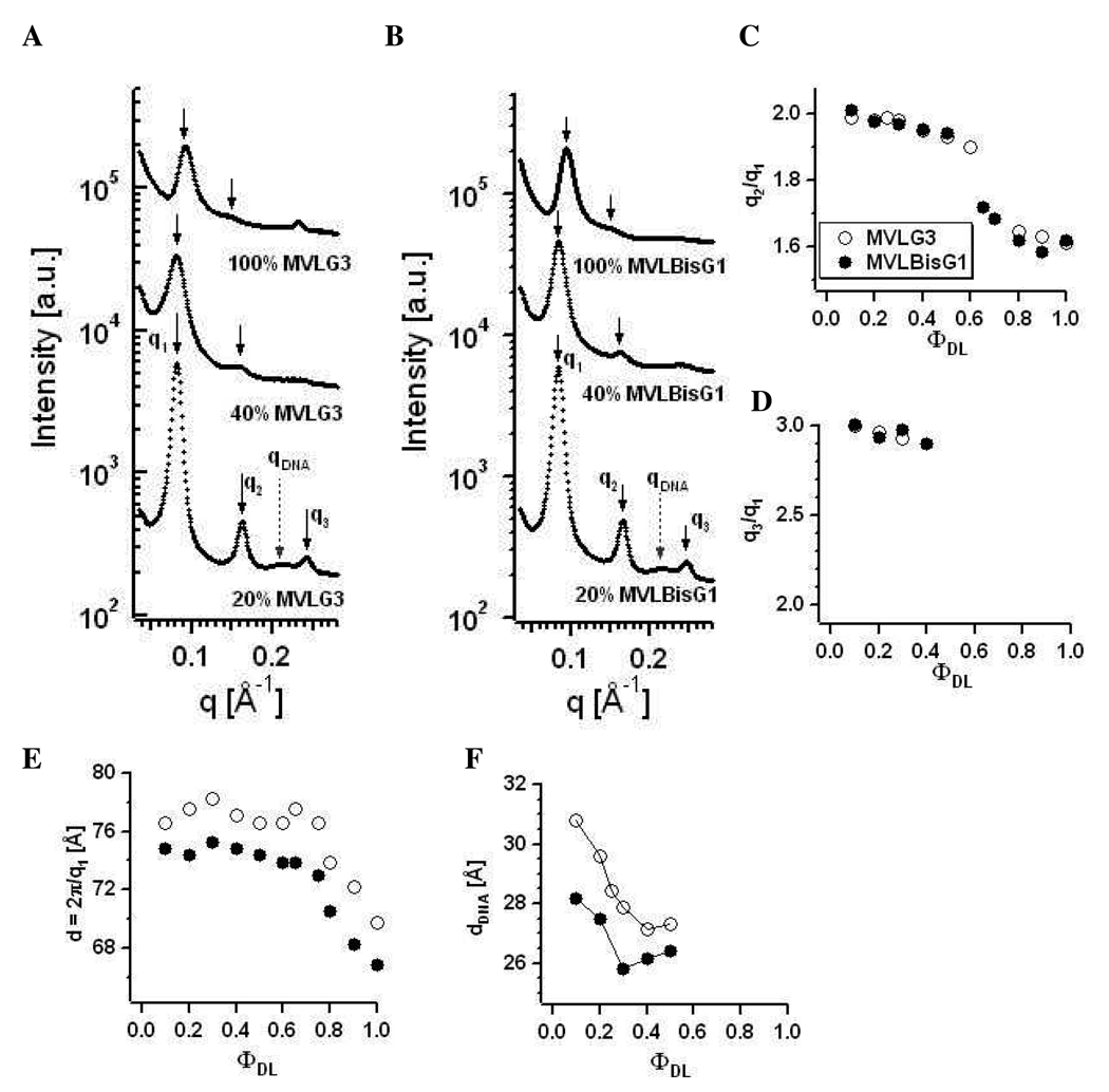
As expected from their headgroup size and charge, MVLG3(8+) or MVLBisG1(8+) form DL/DOPC–DNA complexes which occupy a middle ground in their phase behavior. Figure 12A,B show X-ray diffraction data for MVLG3/DOPC–DNA complexes and MVLBisG1/DOPC–DNA complexes, respectively, at three different compositions: ΦDL = 0.2, 0.4, and 1. DL/DOPC–DNA complexes of both lipids form a lamellar Lαc phase for ΦDL ≤ 0.5. The peaks are marked as in Figure 7. Figure 12C,D shows plots of the ratios of the peak positions q2/q1 and q3/q1 versus ΦDL which signify the nature of the DL–DNA self-assembly. For the lamellar phase, q2 = 2q1 and q3 = 3q1, which is clearly satisfied for ΦDL ≤ 0.5. For 0.5 < ΦDL < 0.8, the ratio between the first and the second order peaks q2/q1 is 1.7 (√3), while q2/q1 = 1.6 for ΦDL ≥ 0.8. This suggests a sequence of phases similar to that observed for MVLBisG2/DOPC–DNA complexes, from Lαc to HIC to a distorted hexagonal phase. An indication of a DNA bundle phase is only seen for ΦMVLG3 = 1.
Figure 12.
X-ray diffraction data for (A) MVLG3/DOPC–DNA complexes and (B) MVLBisG1/DOPC–DNA complexes at ΦDL = 0.2, 0.4, and 1. The diffraction peaks are marked as in Figure 7. (C) Ratio of the first and second order diffraction peaks, q2/q1, and (D) ratio of the first and third order diffraction peaks, q3/q1, plotted as a function of ΦDL. (E) The spacing d = 2π/q1 as a function of ΦDL. (F) Plot of dDNA as a function of increasing ΦDL in lamellar complexes.
Figure 12E shows a plot of d = 2π/q1 for all studied DL–DNA complexes containing MVLG3 and MVLBisG1. Three different regimes, corresponding to the phases described above, can be seen for ΦDL ≤ 0.5, 0.5 < ΦDL < 0.8 and ΦDL ≥ 0.8. In the lamellar regime, at ΦDL ≤ 0.5, the lipid bilayer spacing is constant at d = 77 Å for MVLG3 and d = 75 Å for MVLBisG1. Broadening of the lamellar peaks with increasing ΦDL occurs for both of these octavalent lipids, consistent with an increased disorder in the DL–DNA complexes. This is also reflected by the fact that no third order diffraction peak can be observed for ΦDL > 0.4 (cf. Figure 12D). For lamellar complexes, the DNA correlation peak allows calculation of the DNA spacing as shown in Figure 12F, where dDNA is seen to decrease from 31 Å at ΦMVLG3 = 0.1 to 27 Å at ΦMVLG3 = 0.5 for MVLG3 and from 28 Å at ΦMVLBisG1 = 0.1 to 26 Å at ΦMVLBisG1 = 0.5 for MVLBisG1. Again, this demonstrates a very condensed arrangement of DNA already at low ΦDL.
Correlations between Structure and TE of DL–DNA Complexes
Our structural studies of DL–DNA complexes have confirmed the validity of the universal TE curve for lamellar complexes.22 DL/DOPC–DNA complexes in the LαC phase, i.e., MVLG2/DOPC–DNA complexes at all ΦDL and DNA complexes of the other DLs at low ΦDL, show the universal behavior. Interestingly, TE of the HIC phase and the new distorted hexagonal and DNA bundle phases is not only high but independent of ΦDL and thus σM. The appearance of non-lamellar phases therefore coincides with the deviation from the universal TE curve, suggesting a different mechanism of action for the different structures of DNA complexes. This was already confirmed for inverted hexagonal (HIIC) CL–DNA complexes. In that case, a model was proposed that recognized the importance of the outer (water-facing) layer of positive curvature around the inverted hexagonal CL–DNA complex.23 The lipids in the outer layer have a negative spontaneous curvature and thus are energetically frustrated, which favors fusion of the complexes’ membranes with extra-cellular and endosomal membranes encountered along the gene transfer pathway.
A different reasoning is required in the case of DL–DNA complexes, which not only lack an energetically frustrated outer layer but also exhibit enhanced TE (over lamellar complexes of the same σM) in a different regime, where release of DNA from the complex is thought to be limiting TE. Both the HIC phase and the distorted hexagonal phase exhibit a continuous sub-structure of DNA within the complexes, in contrast to the LαC phase, and the DNA bundle phase observed with MVLBisG2 even seems to allow the delivery of a lipid-free sub-phase of DNA. Thus, the barrier of DNA release from the lipid carrier in the cytoplasm may be lower for these novel structures. Of note, the efficient DNA delivery by DL–DNA complexes in the hexagonal, distorted hexagonal and DNA bundle phases distinguishes them from surfactant-based systems where similar phases of micelles arranged in hexagonal arrays with DNA have been reported.44,45 Due to the toxicity of surfactants, their DNA complexes can not be used as gene delivery carriers.
Conclusions
Understanding the pathways and mechanisms governing the interaction of CL–DNA complexes and cells is crucial to make lipid-mediated gene delivery therapeutically viable. The complexity of the transfection process—from initial attachment of a CL–DNA complex to the plasma membrane to internalization of the complex via endocytosis, its release from the endosome followed by the dissociation of the CLs from the DNA and finally the transport of the DNA into the nucleus followed by successful gene expression—suggests that an interplay of many critically important parameters needs to be considered in order to achieve a successful transfection. Recently, the membrane charge density (σM) of the complex was identified as one of such parameter controlling the TE of lamellar (Lαc) CL–DNA complexes22 of cationic lipids with with headgroup valencies from 1+ to 5+. TE of DNA complexes of the lipids with dendritic headgroups (DLs) investigated here (which were designed to exceed the previously achieved membrane charge densities due to their very high headgroup valencies ranging from 4+ to 16+) strongly deviates from this curve at high σM.
Our studies of the DL/DOPC mixtures and their DNA complexes using X-ray diffraction, optical microscopy and cryo-TEM have shed light on the causes of this unexpected behavior. The phase behavior of the DL–DNA complexes strongly depends on the headgroup charge. MVLG2(4+)/DOPC–DNA complexes exhibit the lamellar phase at all ΦDL. In stark contrast, MVLBisG2(16+)/DOPC–DNA complexes remain lamellar only for ΦDL ≤ 0.2. In a narrow regime around ΦDL = 0.25, the hexagonal phase HIC, consisting of a hexagonal lattice of cylindrical lipid micelles and a DNA honeycomb lattice, is formed. At ΦDL > 0.3, XRD suggests formation of a distorted HIC phase. For ΦDL ≥ 0.5, this phase coexists with a bundle phase of DNA condensed by the depletion-attraction effect of DL micelles. Occupying the middle ground, MVLG3(8+)/DOPC–DNA complexes and MVLBisG1(8+)/DOPC complexes remain lamellar for ΦDL ≤ 0.5, when a phase transition towards the distorted hexagonal phase occurs. The structural transitions from the lamellar phase to the new hexagonal phases of DL–DNA complexes coincide with the deviation from the universal TE behavior of lamellar complexes at high σM. The hexagonal phases of DL–DNA complexes are highly transfecting, and their high TE is independent of σM. This strongly suggests a novel mechanism of action for these DL–DNA complex phases. Inefficient release of DNA from the highly charged membranes has been proposed to cause the drop in TE of lamellar complexes at high σM. It seems plausible that both the hexagonal phases (which exhibit a continuous DNA phase) and in particular the DNA bundle phase do not suffer from a similar barrier once they escape the endosome and reach the cytoplasm.
Acknowledgement
This work was supported by NIH GM-59288, NSF-DMR 0803103 and DOE grant DE-FG02-06ER46314. Cryo-TEM experiments were conducted at the National Resource for Automated Molecular Microscopy which is supported by the NIH National Center for Research Resources P41 program. The X-ray diffraction work was carried out at the Stanford Synchrotron Radiation Laboratory which is supported by the Department of Energy.
References
- 1.Edelstein ML, Abedi MR, Wixon J, Edelstein RM. J. Gen. Med. 2004;6:597. doi: 10.1002/jgm.619. [DOI] [PubMed] [Google Scholar]
- 2.Edelstein ML, Abedi MR, Wixon J. J. Gen. Med. 2007;9:833. doi: 10.1002/jgm.1100. [DOI] [PubMed] [Google Scholar]
- 3. http://www.wiley.co.uk/genetherapy/clinical.
- 4.Ewert K, Slack NL, Ahmad A, Evans HM, Lin AJ, Samuel CE, Safinya CR. Curr. Med. Chem. 2004;11:133. doi: 10.2174/0929867043456160. [DOI] [PubMed] [Google Scholar]
- 5.Clark PR, Hersh EM. Curr. Opin. Mol. Ther. 1999;1:158. [PubMed] [Google Scholar]
- 6.Chesnoy S, Huang L. Annu. Rev. Biophys. Biomol. Str. 2000;29:27. doi: 10.1146/annurev.biophys.29.1.27. [DOI] [PubMed] [Google Scholar]
- 7.Byk G, Dubertret C, Escriou V, Frederic M, Jaslin G, Rangara R, Pitard B, Crouzet J, Wils P, Schwartz B, Scherman D. J. Med. Chem. 1998;41:224. doi: 10.1021/jm9704964. [DOI] [PubMed] [Google Scholar]
- 8.Huang L, Hung M-C, Wagner E. Non-Viral Vectors for Gene Therapy. 2nd ed. Vol. 53. San Diego: Elsevier; 2005. [Google Scholar]
- 9.Mahato RI, Kim SW. Pharmaceutical Perspectives of Nucleic Acid-Based Therapeutics. London and New York: 2002. [Google Scholar]
- 10.Ewert KK, Ahmad A, Evans HM, Safinya CR. Expert Opin. Biol. Ther. 2005;5:33. doi: 10.1517/14712598.5.1.33. [DOI] [PubMed] [Google Scholar]
- 11.Boussif O, Lezoualch F, Zanta MA, Mergny MD, Scherman D, Demeneix B, Behr JP. Proc. Natl. Acad. Sci. U.S.A. 1995;92:7297. doi: 10.1073/pnas.92.16.7297. [DOI] [PMC free article] [PubMed] [Google Scholar]
- 12.Thomas CE, Ehrhardt A, Kay MA. Nat. Rev. Gen. 2003;4:346. doi: 10.1038/nrg1066. [DOI] [PubMed] [Google Scholar]
- 13.Roth CM, Sundaram S. Annu. Rev. Biomed. Eng. 2004;6:397. doi: 10.1146/annurev.bioeng.6.040803.140203. [DOI] [PubMed] [Google Scholar]
- 14.Byk G, Dubertret C, Escriou V, Frederic M, Jaslin G, Rangara R, Pitard B, Crouzet J, Wils P, Schartz B, Scherman D. J. Med. Chem. 1998;41:224. doi: 10.1021/jm9704964. [DOI] [PubMed] [Google Scholar]
- 15.Behr JP. Bioconjugate Chem. 1994;5:382. doi: 10.1021/bc00029a002. [DOI] [PubMed] [Google Scholar]
- 16.Miller AD. Angew. Chem. Int. Ed. Engl. 1998;37:1768. [Google Scholar]
- 17.Zabner J. Adv. Drug Delivery Rev. 1997;27:17. doi: 10.1016/s0169-409x(97)00019-7. [DOI] [PubMed] [Google Scholar]
- 18.Ewert KK, Evans HM, Zidovska A, Bouxsein NF, Ahmad A, Safinya CR. J. Am. Chem. Soc. 2006;128:3998. doi: 10.1021/ja055907h. [DOI] [PubMed] [Google Scholar]
- 19.Koltover I, Salditt T, Rädler JO, Safinya CR. Science. 1998;281:78. doi: 10.1126/science.281.5373.78. [DOI] [PubMed] [Google Scholar]
- 20.Radler JO, Koltover I, Salditt T, Safinya CR. Science. 1997;275:810. doi: 10.1126/science.275.5301.810. [DOI] [PubMed] [Google Scholar]
- 21.Tranchant I, Thompson B, Nicolazzi C, Mignet N, Scherman D. J. Gen. Med. 2004;6:S24. doi: 10.1002/jgm.509. [DOI] [PubMed] [Google Scholar]
- 22.Ahmad A, Evans HM, Ewert K, George CX, Samuel CE, Safinya CR. J. Gen. Med. 2005;7:739. doi: 10.1002/jgm.717. [DOI] [PubMed] [Google Scholar]
- 23.Lin AJ, Slack NL, Ahmad A, George CX, Samuel CE, Safinya CR. Biophys. J. 2003;84:3307. doi: 10.1016/S0006-3495(03)70055-1. [DOI] [PMC free article] [PubMed] [Google Scholar]
- 24.Ewert K, Ahmad A, Evans HM, Schmidt HW, Safinya CR. J. Med. Chem. 2002;45:5023. doi: 10.1021/jm020233w. [DOI] [PubMed] [Google Scholar]
- 25.Bosman AW, Janssen HM, Meijer EW. Chem. Rev. 1999;99:1665. doi: 10.1021/cr970069y. [DOI] [PubMed] [Google Scholar]
- 26.Malik N, Wiwattanapatapee R, Klopsch R, Lorenz K, Frey H, Weener JW, Meijer EW, Paulus W, Duncan R. J. Control. Release. 2000;65:133. doi: 10.1016/s0168-3659(99)00246-1. [DOI] [PubMed] [Google Scholar]
- 27.KukowskaLatallo JF, Bielinska AU, Johnson J, Spindler R, Tomalia DA, Baker JR. Proc. Natl. Acad. Sci. U.S.A. 1996;93:4897. doi: 10.1073/pnas.93.10.4897. [DOI] [PMC free article] [PubMed] [Google Scholar]
- 28.Rudolph C, Lausier J, Naundorf S, Muller RH, Rosenecker J. J. Gen. Med. 2000;2:269. doi: 10.1002/1521-2254(200007/08)2:4<269::AID-JGM112>3.0.CO;2-F. [DOI] [PubMed] [Google Scholar]
- 29.Bielinska AU, Yen A, Wu HL, Zahos KM, Sun R, Weiner ND, Baker JR, Roessler BJ. Biomaterials. 2000;21:877. doi: 10.1016/s0142-9612(99)00229-x. [DOI] [PubMed] [Google Scholar]
- 30.Braun CS, Fisher MT, Tomalia DA, Koe GS, Koe JG, Middaugh CR. Biophys. J. 2005;88:4146. doi: 10.1529/biophysj.104.055202. [DOI] [PMC free article] [PubMed] [Google Scholar]
- 31.Evans HM, Ahmad A, Ewert K, Pfohl T, Martin-Herranz A, Bruinsma RF, Safinya CR. Phys. Rev. Lett. 2003;91 doi: 10.1103/PhysRevLett.91.075501. [DOI] [PubMed] [Google Scholar]
- 32.Ewert KK, Evans HM, Bouxsein NF, Safinya CR. Bioconjugate Chem. 2006;17:877. doi: 10.1021/bc050310c. [DOI] [PubMed] [Google Scholar]
- 33.Quispe J, Damiano J, Mick SE, Nackashi DP, Fellmann D, Ajero TG, Carragher B, Potter CS. Microsc. Microanal. 2007;13:365. doi: 10.1017/S1431927607070791. [DOI] [PubMed] [Google Scholar]
- 34.Suloway C, Pulokas J, Fellmann D, Cheng A, Guerra F, Quispe J, Stagg S, Potter CS, Carragher B. J. Struct. Biol. 2005;151:41. doi: 10.1016/j.jsb.2005.03.010. [DOI] [PubMed] [Google Scholar]
- 35.Takahashi T, Harada A, Emi N, Kono K. Bioconjugate Chem. 2005;16:1160. doi: 10.1021/bc050012f. [DOI] [PubMed] [Google Scholar]
- 36.Koltover I, Salditt T, Safinya CR. Biophys. J. 1999;77:915. doi: 10.1016/S0006-3495(99)76942-0. [DOI] [PMC free article] [PubMed] [Google Scholar]
- 37.Boger DL, Fink BE, Brunette SR, Tse WC, Hedrick MP. J. Am. Chem. Soc. 2001;123:5878. doi: 10.1021/ja010041a. [DOI] [PubMed] [Google Scholar]
- 38.Tristram-Nagle S, Petrache HI, Nagle JF. Biophys. J. 1998;75:917. doi: 10.1016/S0006-3495(98)77580-0. [DOI] [PMC free article] [PubMed] [Google Scholar]
- 39.Podgornik R, Rau DC, Parsegian VA. Macromolecules. 1989;22:1780. [Google Scholar]
- 40.Farago O, Gronbech-Jensen N. Biophys. J. 2007;92:3228. doi: 10.1529/biophysj.106.096990. [DOI] [PMC free article] [PubMed] [Google Scholar]
- 41.Zidovska A, Ewert KK, Quispe J, Carrgaher B, Potter CS, Safinya CR. Langmuir. 2009;25 doi: 10.1021/la8022375. (Accepted) [DOI] [PMC free article] [PubMed] [Google Scholar]
- 42.Conwell CC, Vilfan ID, Hud NV. Proc. Natl. Acad. Sci. U.S.A. 2003;100:9296. doi: 10.1073/pnas.1533135100. [DOI] [PMC free article] [PubMed] [Google Scholar]
- 43.Hud NV, Downing KH. Proc. Natl. Acad. Sci. U.S.A. 2001;98:14925. doi: 10.1073/pnas.261560398. [DOI] [PMC free article] [PubMed] [Google Scholar]
- 44.Zhou SQ, Liang DH, Burger C, Yeh FJ, Chu B. Biomacromolecules. 2004;5:1256. doi: 10.1021/bm034524d. [DOI] [PubMed] [Google Scholar]
- 45.Ghirlando R, Wachtel EJ, Arad T, Minsky A. Biochemistry. 1992;31:7110. doi: 10.1021/bi00146a012. [DOI] [PubMed] [Google Scholar]


