Abstract
The mouse cerebral cortex was imaged in situ by photoacoustic tomography. Instead of a flat ultrasonic transducer, a virtual point detector based on a high-numerical-aperture positively focused transducer was used. This virtual point detector has a wide omnidirectional acceptance angle, a high sensitivity and a negligible aperture effect. In addition, the virtual point detector can be located much more closely to the object during the detection. Compared with a finite size flat transducer, images generated by using this virtual point detector have both uniform signal-to-noise ratio and resolution.
Keywords: photoacoustic tomography, high numerical aperture, virtual point detector
I. Introduction
Photoacoustic (PA) tomography (PAT) is an emerging biomedical imaging modality, which detects optical absorbers, such as blood vessels, inside tissue. Based on the photoacoustic mechanism [1, 2], PAT uses an non-ionizing illumination source and is non-invasive. Moreover, by using diffused light instead of ballistic light, PAT can image deeper into tissue than other pure high-resolution optical imaging methods, such as optical coherence tomography (OCT) and two-photon tomography. PAT has been successfully applied in imaging both small animal and human tissues [3–5].
Among many ultrasonic detection methods for PAT, scanning with a single finite size flat transducer is widely used owing to its simplicity and high sensitivity. However, the finite size flat transducer not only decreases lateral resolution as the object approaches the transducer (aperture effect) [6], but also limits the detection region due to its narrow acceptance angle. By contrast, a real point detector with a very small active surface suffers from poor sensitivity but has a wide acceptance angle and a negligible aperture effect. Thus, a point detector with a high sensitivity is highly desirable for PAT. Moreover, both exact and approximate image reconstruction algorithms have been developed for PAT with point detectors [7, 8].
Virtual point detection methods have already been introduced in photoacoustic tomography [9–12]. By taking advantages of the integrated ultrasonic detectors, detected ultrasonic waves are primarily equivalent to waves that come through a “virtual point”, such as the ring center or the focal point. This method uses the location of the “virtual point” to calculate the time delay of the ultrasonic signal. Three kinds of virtual point detectors have been developed: 3D focused detector [9], 2D ring detector [10] and 2D high-numerical-aperture (NA) transducer [12]. The first one has been proved to in increase the image resolution for objects close to the focal zone in the photoacoustic microscopy (PAM). The second and third virtual point detectors have similar construction. The ring detector has already been demonstrated by both phantom and animal experiments in PAT. However, the ring virtual point detector limits its field of view (FOV) within the ring.
We previously introduced a 2D high-NA focused ultrasonic transducer for PAT with phantom experiments. This virtual point detector has a large physical detection surface and a small effective detection volume. Phantom experiments demonstrated that this virtual point detector has a comparable sensitivity to a finite size flat transducer, as well as a much wider acceptance angle than a flat transducer. Owing to the negligible aperture effect, this virtual point detector can generate images with uniform resolution. In the next section, we briefly describe the virtual point detector. In Section III, we image the cerebral cortex of a mouse in situ using this virtual point detector.
II. A High-NA-Based Virtual Point Detector
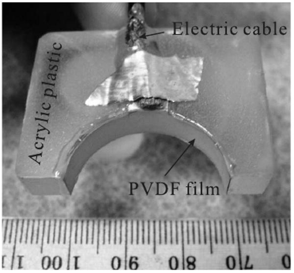
The transducer's active material was a metallized polyvinylidene fluoride (PVDF) film (from Measurement Specialties, Inc.), with a thickness of 110 μm. The 2D high-NA focused transducer was constructed by a by cutting the film in a 6.0 mm-wide strip and gluing it on an acrylic plastic surface, as seen in Fig. 1. The transducer had a half circular shape with a radius of 13 mm, forming a positively focused transducer with NA = 1. The estimated center frequency was around 6.0 MHz. From the calculation at its center frequency [12], the focal width of this high-NA transducer is about 120 μm. The performance of this 2D virtual point detector had been previously demonstrated by phantom experiments [12]. The width of the PVDF strip constrains the elevation resolution to be about 6.0 mm, in other words, the image slice practically has a thickness of about 6.0 mm. For comparison, we further constructed a square flat PVDF transducer, 5.0 mm by 5.0 mm.
FIG. 1.

A virtual point detector based on a positively focused transducer.
III. Animal Experiments
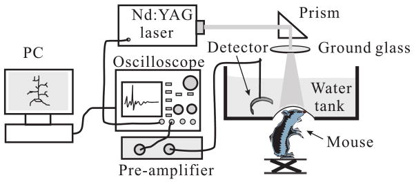
The cerebral cortex of a euthanized Swiss Webster mouse (Harlan Sprague Dawley Incorporated, Indianapolis, Indiana, ∼ 29 g) was imaged in situ by PAT. The hair on the mouse head was gently depilated by using a hair removal lotion, then the mouse head was fixed on a homemade animal holder. The experimental setup is shown in Fig. 2. The illumination source was a Nd:YAG laser (Brilliant B, Quantel), which generated 6.5 ns, 532 nm laser pulses with a repetition rate of 10 Hz. The illumination laser was homogenized by a ground glass so that the whole cortex region of the mouse could be illuminated. A hole at the bottom of the water tank was sealed by a thin transparent membrane. The mouse head, after a layer of water-based gelatin was applied to it, protruded up into the tank against that membrane. Ultrasonic detectors, either a flat or a high-NA positively focused transducer, were immersed in water at the same horizontal plane as the mouse cortex. Both detectors evenly scanned the cortex along a horizontal circle, stopping at 240 points, and the signals were averaged 20 times at each stop. The PA signals were first amplified 40 dB by a pre-amplifier, and then were recorded by an oscilloscope (Tektronix TDS640A) with a sampling rate of 50 MHz. Finally, the recorded signals were sent to a PC for image reconstruction.
FIG. 2.
Experimental setup of the animal experiment.
Our image reconstruction is based on the solid-angle-weighted image reconstruction algorithm as described in [13]. We use the scanning center as the coordinate origin. Detectors, flat or virtual point detectors, lie at location rn (n=1,⋯, 240). We further simplified the algorithm by approximately using the detected signal p instead of the actual pressure and its temporal derivative term. The algorithm used in this paper is
| (1) |
where p0(r) is the reconstructed value at location r, p(rn, t) is the detected signal at time t, nˆ is the unit vector of rn, and c is the speed of the sound.
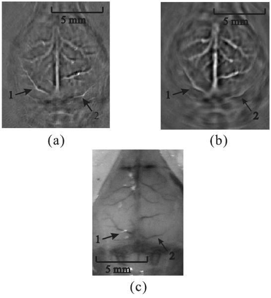
Fig. 3(a) shows the result of scanning with a high-NA-based virtual point detector; the scanning radius was about 2.7 cm. Fig. 3(b) shows the result of scanning with a flat transducer; the scanning radius was about 4.1 cm.
FIG. 3.

Reconstructed PAT images. (a) From data gathered by a positively focused PVDF transducer; the scanning radius of the virtual point was 2.7 cm. (b) From data gathered by a flat transducer; the scanning radius was 4.1 cm. (c) Photograph of the mouse cortex taken after photoacoustic data acquisition.
Although the scanning radius of the virtual point detector was shorter than that of the flat transducer, the reconstructed image of Fig. 3(a) exhibits a uniform resolution. Moreover, the reconstructed images of peripheral blood vessels in Fig. 3(b) are blurred. For instance, we marked two cortex vessels, “1” and “2”. Compared with the photograph of the mouse cortex in Fig. 3(c), both marked vessels were successfully reconstructed by using a virtual point detector (Fig. 3(a)), and the image quality is significantly improved over the image obtained by using a flat transducer (Fig. 3(b)). This result was consistent with the results from phantom experiments in [12].
To alleviate the image blurring, the finite size flat transducer had to be placed much further away from the scanning center, at the expense of convenience and signal strength. However, the finite size flat transducer has higher signal-to-noise-ratio (SNR) in imaging regions close to the scanning center. It is because it has a larger detection surface than the size of the virtual point, and the ultrasound wave from regions close to the center approximately perpendicularly reach the surface of the finite size flat transducer. By comparison, high-NA 2D detector only effectively detects ultrasonic waves passing through the virtual point.
IV. Conclusions
In summary, a 2D virtual point detector was successfully applied in PAT for cortex imaging. Compared with a flat transducer, the virtual point detector, with a similar sensitivity to the flat transducer, can image the object at a much closer distance with more uniform resolution. In addition, the closer the detector to the source, the higher the SNR. Such a PAT system can also be built more compactly, and will have a negligible aperture effect. This virtual point detector is also important to thermoacoustic tomography (TAT), where the illumination source is replaced by a microwave source. An important potential application is that the virtual point method can be applied in breast imaging by PAT or TAT. Due to the size of the breast, it is inconvenient to place ultrasonic detectors far away from the breast. Moreover, this 2D virtual point detector can be used to construct the PA detection array, by either evenly placing multiple detectors along the detection circular trajectory or by making a stack of detectors for multi-layer detection. In addition to PAT and TAT, this virtual point detector can also be potentially implemented in other fields that use ultrasonic detectors, such as ultrasonic tomography.
Acknowledgments
This project was sponsored in part by National Institutes of Health Grant Nos. R01 NS46214(BRP) and R01 EB000712. L.W. has a financial interest in Endra, Inc., which, however, did not support this work.
References
- 1.Xu MH, Wang LHV. Review of Scientific Instruments. 2006;77 [Google Scholar]
- 2.Wang LV, Wu Hi. Biomedical Optics: Principles and Imaging. Wiley; Hoboken, N.J.: 2007. [Google Scholar]
- 3.Hoelen CGA, de Mul FFM, Pongers R, Dekker A. Optics Letters. 1998;23:648. doi: 10.1364/ol.23.000648. [DOI] [PubMed] [Google Scholar]
- 4.Wang XD, Pang YJ, Ku G, Xie XY, Stoica G, Wang LHV. Nature Biotechnology. 2003;21:803. doi: 10.1038/nbt839. [DOI] [PubMed] [Google Scholar]
- 5.Siphanto RI, Thumma KK, Kolkman RGM, van Leeuwen TG, de Mul FFM, van Neck JW, van Adrichem LNA, Steenbergen W. Opt Express. 2005;13:89. doi: 10.1364/opex.13.000089. [DOI] [PubMed] [Google Scholar]
- 6.Xu M, Wang LV. Physical Review E. 2003;67:056605. doi: 10.1103/PhysRevE.67.056605. [DOI] [PubMed] [Google Scholar]
- 7.Xu MH, Wang LHV. Physical Review E. 2005;71:016706. doi: 10.1103/PhysRevE.71.016706. part 2. [DOI] [PubMed] [Google Scholar]
- 8.Kruger RA, Reinecke DR, Kruger GA. Medical Physics. 1999;26:1832. doi: 10.1118/1.598688. [DOI] [PubMed] [Google Scholar]
- 9.Li ML, Zhang HF, Maslov K, Stoica G, Wang LHV. Optics Letters. 2006;31:474. doi: 10.1364/ol.31.000474. [DOI] [PubMed] [Google Scholar]
- 10.Yang XM, Li ML, Wang LHV. Applied Physics Letters. 2007;90:251103. [Google Scholar]
- 11.Yang XM, Wang LV. Journal of Biomedical Optics. 2007;12 doi: 10.1117/1.2823076. [DOI] [PubMed] [Google Scholar]
- 12.Li C, Wang LHV. Applied Physics Letters. 2008;3:033902. doi: 10.1063/1.2963365. submitted to. [DOI] [PMC free article] [PubMed] [Google Scholar]
- 13.Xu MH, Wang LHV. Physical Review E. 2005;71:016706. doi: 10.1103/PhysRevE.71.016706. [DOI] [PubMed] [Google Scholar]


