Abstract
The ability to visualize and track temporarily or permanently implanted metal devices is important in many applications ranging from diagnosis to therapy. Specifically, reliable imaging of metal needles is required in today’s clinical settings. Currently, ultrasound is utilized to image a needle inserted into tissue in real time. However, the diagnostic value and tracking ability of these images depends highly on the orientation of the needle, and also its proximity to regions of interest in the tissue. We examine the use of photoacoustic imaging combined with current ultrasound imaging methods to obtain high-contrast images of commonly used needles in the body. Experiments were performed using 21 G and 30 G needles inserted into ex vivo porcine tissue and tissue-mimicking phantoms. The needles and surrounding tissue were imaged using an ultrasound imaging system interfaced with the pulsed laser source necessary for photoacoustic imaging. The results suggest that photoacoustic imaging, combined with ultrasound imaging, is capable of real-time, high-contrast, and high-spatial-resolution visualization of metal implants within anatomical landmarks of the background tissue.
Keywords: ultrasound, photoacoustics, imaging, metal, needles, image-guided biopsy
Introduction
A wide variety of metal implants are used clinically within the human body. These range from permanently implanted metals such as orthopedic replacements or coronary arterial stents, and include temporarily implanted metals such as surgical staples. Hypodermic needles are one such temporary metal implant used for a wide variety of clinical applications. Metal needles are commonly used for localized drug delivery, such as in cancer therapy, or for tissue collection in biopsy.1 In either case, the ability to visualize both the anatomical surrounding structures and the advancing needle tip is required.2 Accurate imaging is necessary to guide the needle to the targeted location.3 Needle deflection and deformation can occur when inserting needles into soft, nonhomogeneous tissues,4 which can affect the localized accuracy of insertion.5 Currently, the most commonly used clinical strategy to visualize the direction of the needle shaft in real time is ultrasound guidance.1 However, the needle tip can often be visualized better than the needle shaft because of the irregular surface of the machine-cut bevel, which scatters the ultrasound (US) beam in all directions, reflecting the beam in part back to the transducer.2 However, visibility of the tip alone is not sufficient for the clinician to gauge the insertion angle of the needle. Visibility of the needle shaft is dependent on the angle of the needle relative to the transducer6 and is best visualized only when perpendicular and in the plane of the US transducer. Needle deflections away from the transducer of only a few degrees are usually enough to conceal the US signal from the needle. To overcome these issues, mechanical or optical needle guides are often used to keep the needle in the transducer plane.7, 8 However, these guides restrict needle movement when fine adjustments are needed by medical operators; therefore, many clinicians prefer using a freehand technique during needle insertion and injection.3
US imaging of metal needles also produces an unexpected echographic pattern resembling the shape of a comet tail.9 The pattern is due to reverberations within the needle and is dependent on the acoustic impedance mismatch between the needle and its surroundings. In fact, these artifacts are present in US imaging of any metallic object.10 While these artifacts can be helpful in determining the presence of foreign metal in vivo, the existence of the comet tail pattern prevents visibility of objects directly below and adjacent to the needle.11 This effect can detrimentally affect the ability to determine needle position relative to the background tissue.
In this paper, we demonstrate the ability of combined US and photoacoustic (PA) imaging to visualize metal needles inserted into tissue. Briefly, the PA effect results from irradiating an object with a pulsed laser beam to produce a thermoacoustic response. Light absorbed in a specific local region is converted into heat, and then converted into pressure due to the thermoelastic expansion of the object. An US transducer detects the produced pressure, which is linearly related to the optical absorption coefficient μa and the localized laser fluence. Since metal is generally highly absorbing, relative to tissue, the PA signal from metal objects should be much higher relative to the background tissue. Experiments were performed using common commercially available clinical metal needles inserted into tissue and tissue-mimicking phantoms. The presence of these clinical needles was detected using combined US and PA imaging. In each experiment, the acquired PA images outlined the presence of the metal implant, and the US image provided information about the surrounding structure. During postprocessing, the comet tail artifacts were reduced using a filtering approach, thus enabling the previously distracted background in PA imaging to be better visualized. The combined US and PA imaging enabled accurate measurements of the needle’s position within the tissue. The accuracy of these measurements demonstrates the usefulness of PA imaging in visualizing metal needles and other metal implants in vivo.
Methods and Materials
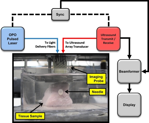
To test the feasibility of US and PA to image metal needles in tissue, imaging studies were conducted using different sizes of needles. In the first experiment, a Cortex ultrasound imaging system (Winprobe Corporation, North Palm Beach, Florida) was used for rf data acquisition (Fig. 1). This US system was interfaced with a 7-MHz center frequency, 14-mm-wide, 128-element linear array transducer to image the needles. An Nd:YAG pump laser output (Vibrant B, Opotek, Inc., Carlsbad, California) at 1064 nm was used to optically illuminate the tissue phantom. Laser fluence in all experiments was measured to be approximately 10 mJ∕cm2. Laser light was delivered through an 18-fiber optical bundle fixed around the transducer,12 and the needle sample was placed in the imaging plane of the US imaging transducer (Fig. 1). This arrangement enabled both light and sound delivery along the same plane. Each fiber in the bundle was 0.6 mm in diameter with a numerical apperture (NA) of 0.22. Fiber bundle efficiency was approximately 60%. In this experiment, a 30-gauge (30 G)×1.0-in. hypodermic syringe needle (Fig. 2), made of 305 bulk stainless steel (Becton Dickinson, Franklin Lakes, New Jersey) was inserted horizontally into a fresh healthy porcine muscle specimen. The approximately 30×30×30 mm3 tissue sample was immersed in water for acoustic coupling between the US transducer and the tissue (Fig. 1). US and PA rf signals were collected with the needle oriented orthogonal to the imaging plane, then the transducer was axially rotated 90 deg, and the imaging procedure repeated, capturing the length of the needle in the imaging plane.
Figure 1.
Experimental setup for imaging metal needles in a porcine tissue sample. An imaging probe consisting of a 7-MHz linear array transducer and an 18-fiber bundle was positioned on the top of the sample. The pork sample was placed in a water tank for the purposes of acoustic coupling. The sample was irradiated at a 1064-nm wavelength. Laser fluence was approximately 10 mJ∕cm2.
Figure 2.
Schematic view of the 30-gauge (30 G) and 21-gauge (21 G) needles. The 30 G needle was inserted into pork loin tissue perpendicular, and later reinserted at an angle of approximately 15 deg to the surface of the US transducer. The 21 G needles were inserted at various angles relative to the US transducer.
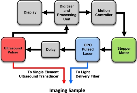
To investigate the angular dependence of the US and PA signal, a second experiment was performed using a 7.5-MHz, f∕4, single-element transducer, mechanically scanned across the axial dimension of a set of needles using both US and PA imaging13 (Fig. 3). The purpose of this experiment was to determine the needle angles at which the metal needle would be visible, both in US and PA imaging and to demonstrate the effectiveness of PA imaging for detecting needles which are more often than not inserted angled from the transducer. Five 21 G×1.0 in. needles made of 305 bulk stainless steel (Becton Dickinson, Franklin Lakes, New Jersey) were positioned both in water and in gelatin phantoms at angles of 0, 5, 10, 20, and 30 deg relative to the horizontal plane, i.e., the surface of the US transducer. The gelatin phantom was created using 6% gelatin by weight, and a small amount (less than 1%) of 40-μm-size silica particles, which served as optical scatterers. PA imaging was conducted at 800 nm and light was delivered using a single optical fiber. The fiber had a diameter of 1.5 mm and an NA of 0.39.
Figure 3.
Experimental setup for imaging of metal needles positioned at different angles in water and gelatin phantom. Imaging was performed with a single element US transducer (7 MHz, f∕4). The center frequency of this transducer was similar to the imaging array used in Fig. 1. The imaging sample was irradiated with 800-nm-wavelength light. Laser fluence was also approximately 10 mJ∕cm2.
Results
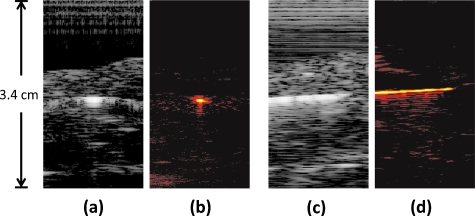
In the first experiment, the metal needle, in porcine tissue, was inserted parallel to the transducer surface and perpendicular to the imaging plane. Cross-sectional US and PA images of the needle and tissue were produced [Figs. 4a, 4b]. The US image [Fig. 4a] shows a bright signal in the middle of the image where the needle is located. Surrounding the needle’s signal is the US speckle obtained from the porcine tissue. The PA image at the same position also showed a bright signal in the center corresponding to the needle cross section. After obtaining these images, the sample was rotated 90 deg relative to the transducer, aligning the needle shaft directly in the imaging plane of the transducer [Figs. 4c, 4d]. Similarly, the US image [Fig. 4c] displays a bright acoustic reflection from the needle, surrounded by acoustic speckle from the tissue background. The PA image of the needle shaft [Fig. 4d] also produced a large signal from the needle, but very little signal from the background, similar to the PA image in Fig. 4b. As the metal needle was placed parallel to the transducer surface in these images, the needle was easily visible in the US and PA images. At this orientation (i.e., a perpendicular angle between the axis of the US beam and longitudinal axis of the needle), the needle produced a strong US signal due to the high specular reflectivity of the needle. US comet-tail artifacts were also created behind the needle since acoustic waves were reflected within the needle, creating additional signals that appeared to propagate beyond and around the needle. The artifacts introduced into the US image, subsequently reduced the ability to determine the precise location of the needle. However, the comet tail made it very easy for the needle’s presence to be identified in the image. The PA signals here also confirmed the presence of the highly absorbing metal needle.
Figure 4.
Images of a hypodermic needle inserted perpendicular to the US transducer. The needle is inserted horizontally through the pork loin sample. The transducer is located toward the top of the images. (a) US image of the needle cross section in pork sample; (b) PA image of needle cross section, where the needle is easily visible; (c) US image of the needle and tissue in the transducer imaging plane; and (d) PA image of the needle in the transducer imaging plane, where the metal needle is clearly visible. The dimensions of the pork loin are approximately 30×30×30 mm3. US images are displayed at 40 dB, PA images at 20 dB.
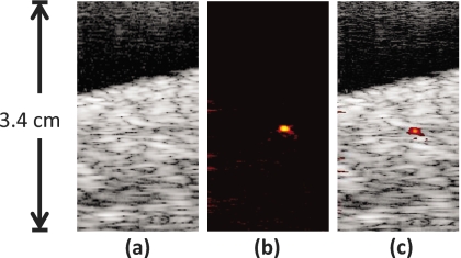
US and PA images (Fig. 5) were also obtained with the needle inserted into the phantom at a slight downward angle. In these images, the cross section of the needle was once again located in the center of the images, similar to Figs. 4a, 4b. However, the needle here was angled away from the transducer. The US image still showed the background speckle of the porcine tissue, but the needle in the center of the image could not be easily visualized [Fig. 5a]. A PA image was also obtained at the same position [Fig. 5b]. Despite the angled needle being invisible in the US image, the PA image still showed a bright spot in the center of the image where the cross section of the needle was located. By combining Figs. 5a, 5b, the coregistered US and PA images displayed the presence of the angled needle in the tissue background [Fig. 5c].
Figure 5.
Images of the hypodermic needle inserted angled approximately 15 deg with respect to horizontal. The needle is repositioned in the same tissue as in Fig. 4. The transducer is oriented at the top of the images. (a) US image of the tissue containing the needle cross section; the angled needle is not visible; (b) PA image of same cross section as (a), the highly absorbing needle appears very clearly; (c) combined US and PA image showing the exact location of the needle within the tissue. US images are displayed at 40 dB, PA images at 20 dB. Since US and PA images are obtained at the same position, the two images are spatially coregistered.
In the US image, the angled needle reflected the acoustic pulses away from the transducer, thereby decreasing the signal intensity from the needle, resulting in decreased visibility in the resulting image. However, the PA signal was not significantly affected by this angular dependence and the needle remained highly visible within the tissue background even when it was not perpendicular to the transducer. In general, the PA response from rounded objects occurs omnidirectionally, which enables the signal to be less affected by the needle angle compared to the US image. Comet-tail artifacts are, however, directionally dependent, which is why they are not visible in the image of an angled needle. Furthermore and more importantly, there is excellent contrast in the PA response between the needle and the background tissue.
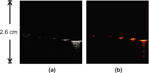
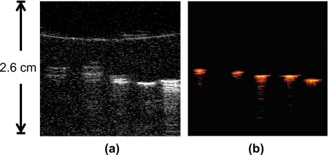
In the second experiment, cross-sectional US and PA images of the five angled 21 G needles were obtained (Fig. 6). From left to right, the needles were inserted into a acrylic holder at decreasing angles from 30 to 0 deg. The US image [Fig. 6a] shows the cross sections of the needle with decreasing visibility as the needle angle was increased. Similarly, the PA image [Fig. 6b] shows the needles at the same position but with less decrease in signal as needle angle was increased. The addition of the gelatin phantom background in Fig. 7 shows both the US and PA images of the needles, similar to Figs. 6a, 6b. The US image of the needles in the gelatin phantom shows overall decreased visibility of the needles in the presence of the background speckle. On the other hand, all the needles were fully visible in the PA image; the PA signal intensity did not decline with needle orientation at the angles used in this experiment. Furthermore, the presence of optical scatterers helped to deliver light within the phantom. Figure 7b shows increased PA signal due to better light delivery to the needles in the phantom.
Figure 6.
Cross-sectional image of five 21 G needles in water. The needles are angled downward with respect to the horizontal plane. From left to right, needles are angled at 30, 20, 10, 5, and 0 deg, respectively.
Figure 7.
Cross-sectional image of five 21 G needles inserted into a tissue-mimicking gelatin phantom containing optical scatterers. From left to right, needles are angled at 30, 20, 10, 5, and 0 deg downward with respect to the horizontal plane.
In both the water (Fig. 6) and the tissue-mimicking phantom (Fig. 7) experiments, the maximum signal intensity came from the needles that were horizontal from the transducer surface. In water, all the needles were at least dimly visible in the US image, although the signal intensity and spatial resolution was severely limited at needles angled greater than 10 deg. The addition of acoustic scatterers in the phantom background made the needles less visible under US. Needles at angles greater than 10 deg were invisible against the background. The PA signals from the needles remained easily visible in the gelatin, except for a slight decrease in signal intensity due to light attenuation from the phantom. This did not adversely affect the imaging of the needles, as they were still very visible due to the high absorption coefficient of metal.
Discussion and Conclusions
US and PA images of needles are shown in Figs. 4567. In each set of images, the PA images showed very high contrast between the metal and the phantom or tissue backgrounds. Indeed, the PA signal from the metal is very strong due to the high optical absorption of metal compared to the gelatin phantom, which has little to no PA response and therefore results in very high contrast. In tissue, high contrast between the metal structure and tissue constituents was also found. Optical absorption of other tissue constituents is generally known to be far lower than that from the metal in the near-IR spectrum range. By comparison, the US image visualized the tissue structure and morphological features. Since the US and PA images were already spatially coregistered, combining the two images showed complementary information. The locations of the metal implants (PA image) were given in relation to the background tissue (US image).
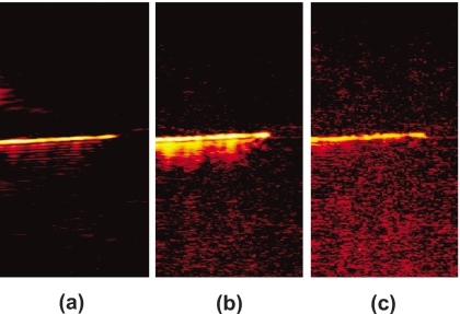
Both experiments showed strong comet-tail artifacts when imaged with US and PA imaging. Fast Fourier transforms (FFTs) of the a-lines containing rf signals showed that the frequency content of the comet tail was slightly different than the center frequency of the transducer. Therefore, bandpass filtering was performed to reduce the artifacts from the PA image of the needle in Fig. 4. Prior to applying the signal filter, comet-tail artifacts could be seen emanating from the position of the needle in the PA image [Fig. 8a]. When correct bandpass filtering was performed (4 to 10 MHz), the comet tail disappeared from the image [Fig. 8c]. However, specifying the incorrect frequency range (3 to 10 MHz) resulted in an undesired treatment of the image and did not correctly remove the image artifacts [Fig. 8b].
Figure 8.
PA image from Fig. 4d showing filtering technique to remove comet-tail artifacts; (a) unfiltered PA image of the horizontal needle, The FFT of the signal shows one frequency peak at the center frequency of the transducer (7 MHz) and one at a lower frequency around 3 MHz, representing the signal from the comet tail; (b) result of bandpass filtering demonstrating incorrect choice of cut-off frequencies (3 to 10 MHz), low-frequency components are still present, blurring out the artifacts; and (c) correct bandpass filtering (4 to 10 MHz), which eliminated the comet-tail artifact. Contrast-to-noise ratios in (a), (b), and (c) were calculated to be 39.3, 38.2, and 32.5 dB, respectively.
Bandpass filtering was able to remove the image artifacts, albeit at a decrease in the contrast-to-noise ratio14, 15 (CNR). Without filtering, the CNR of Fig. 8a was found to be 39.3 dB. Figure 8b was reported to contain a CNR of 38.2 dB, and Fig. 8c had a CNR of 32.5 dB.
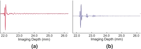
Attempts to perform the same filtering technique to the US image were unsuccessful. Examination of the time domain signal revealed that the comet-tail artifact produced in the US image contained a discontinuous signal different from the PA image. While the resulting artifacts in the US and PA signals were visually similar, the PA comet-tail signal was continuous, decreasing over time, similar to an acoustic reverberation [Fig. 9a]. On the other hand, the US comet tail was discontinuous, having burstlike signals that decreased in amplitude over time [Fig. 9b]. These burstlike signals in the US image are therefore not easily removed without using more advanced filtering methods.
Figure 9.
Individual A-lines of the rf signal through the needle, demonstrating the nature of the comet-tail artifact. Though the images appear similar, the underlying signals are not. (a) PA A-line, the comet-tail artifact appears to be a continuous signal that diminishes over time, and (b) US A-line at the same location. The comet-tail artifact in the US image appears as a discontinuous train of signal bursts that decrease in amplitude over time.
The combined US and PA imaging modality was able to image 1 to 2 cm into tissue, the depth necessary for the imaging of metal needles inserted into the body. The current practice of using US imaging for guidance is ineffective to image metal in all cases, especially where highly reflective surfaces redirect US echoes away from the transducer. In most cases, clinicians are only able to use the US shadows from the metal to infer the location of the needle. The experimental results presented here demonstrate that PA imaging is suitable for imaging metal. Combined with US imaging, the PA signal from the metal inclusions was visible in relation to its position to the surrounding tissue∕phantom structures, which were visible in the US signal.
The use of 1064-nm-wavelength light is a huge advantage for clinical in vivo settings due to the low cost and simplicity of the Nd:YAG laser, deep penetration of the light into tissue, and high PA contrast between metal objects and surrounding tissue. By using a 1064-nm laser, users do not require an expensive, complex laser system to conduct imaging tests. At a 1064-nm wavelength, light offers deep penetration into tissue and therefore imaging will require less laser fluence for the PA signal, while still preserving SNR, CNR, and safety. The imaging studies conducted here used laser energies well below the maximum permissible exposure level set by the ANSI standard. These laser energies coupled with an array-based imaging transducer make it possible to image PA signals in real time. Our setup in this experiment was limited to a repetition rate of 10 Hz, but inexpensive lasers operating at 30 Hz or higher could be used for real-time imaging. The PA contrast in the tissue studies demonstrated that at 1064 nm, metal was more highly absorbing than the surrounding tissue, therefore showing that 1064 nm is an effective wavelength choice for imaging metal in the body.
Though the first PA imaging experiment in this paper was conducted at 1064 nm, the second experiment was conducted at 800 nm, suggesting that multiple wavelengths could be used for spectroscopic PA imaging, which could be utilized to further differentiate between metal and tissue.16 Since the PA effect is directly related to optical absorption, PA data from multiple wavelengths could be used to calculate absorption spectra in the resulting image. Tissue constituents, having a unique optical absorption spectrum from metal, could then be differentiated from the metal, identifying the composition of tissue with respect to the location of metal implants.
Our previous work showed that PA imaging of metal in the body is not limited to needles. A host of metal devices are used in the human body, either temporarily or permanently, many of which must be identified or monitored.17, 18 Combined intravascular US (IVUS) and PA imaging (IVPA) has been shown to image arterial stents and their positioning within the arterial wall.19 The combination of IVUS and IVPA was found to give complementary information as the US image gave structural∕morphological information of the arterial wall, while the IVPA image could hypothetically show the location of the stent, its position within the wall, and also the location of arterial plaques. It has also been proposed that this combined US and PA imaging could be used to image brachytherapy seeds during and after implantation into the body. Brachytherapy seeds are implanted to locally treat prostate cancer. However, the seeds have been found to migrate throughout the body, which can cause problems as they lodge themselves in other areas of the body such as the lungs.20 PA imaging could be used to detect the location of the seeds as they shift around in the prostate. The imaging could be performed tomographically, reconstructing multiple slices of US and PA data to create a 3-D image of a localized region.
It can also be possible to treat metal with substances that have strong absorption peaks at specific wavelengths. This would enable the metal absorption peaks to be tuned toward or away from wavelengths where tissue shows strong PA signal, making the metal components easier to identify alongside other tissue constituents such as cancerous lesions. These coatings could be used concurrently with multiwavelength PA imaging13, 16 to differentiate implants from tissue as unique absorption peaks can be expected from the coated metal. Currently, echogenic needle polymer coatings exist that make the needle tip and shaft highly visible21 under US. Similar coatings with optically absorbing properties could also be coated onto the metal to make metal implants even more visible at other wavelengths in PA imaging. Various molecularly sensitive coatings could also be used so that the absorption properties of the coated metal would change depending on the tissue background in contact with the metal. These metals could quite possibly also be used for specific tissue detection.
Identification of metal in the body requires the visualization of landmarks in the body. The combination of US and PA imaging offers the high contrast of metal implants in PA imaging with the coregistered anatomical positioning of US. Used in real time, this combination can offer a very powerful tool not only for identifying metal implants, but also for identifying their relative location to other structures in the body such as tumors and plaques. This ability to identify metal implants and surroundings is highly necessary in image-guided therapy.
Acknowledgments
The authors would like to graciously acknowledge Mr. Seungsoo Kim of the University of Texas at Austin for his assistance with the data capture software and imaging hardware. Partial support from National Institutes of Health under Grants EB008101, HL096981, and CA141203 is also gratefully acknowledged.
References
- Charboneau J. W., Reading C. C., and Welch T. J., “CT and sonographically guided needle biopsy: current techniques and new innovations,” Am. J. Roentgenol. 154, 1–10 (1990). [DOI] [PubMed] [Google Scholar]
- Chapman G. A., Johnson D., and Bodenham A. R., “Visualisation of needle position using ultrasonography,” Anaesthesia 61, 148–158 (2006). 10.1111/j.1365-2044.2005.04475.x [DOI] [PubMed] [Google Scholar]
- Chin K. J., Perlas A., Chan V. W., and Brull R., “Needle visualization in ultrasound-guided regional anesthesia: challenges and solutions,” Reg. Anesth. Pain Med. 33, 532–544 (2008). [DOI] [PubMed] [Google Scholar]
- Abolhassani N., Patel R. V., and Ayazi F., “Minimization of needle deflection in robot-assisted percutaneous therapy,” Int J. Med. Robot 3, 140–148 (2007). [DOI] [PubMed] [Google Scholar]
- Nath S., Chen Z., Yue N., Trumpore S., and Peschel R., “Dosimetric effects of needle divergence in prostate seed implant using 125I and 103Pd radioactive seeds,” Med. Phys. 27, 1058–1066 (2000). 10.1118/1.598971 [DOI] [PubMed] [Google Scholar]
- Schafhalter-Zoppoth I., McCulloch C. E., and Gray A. T., “Ultrasound visibility of needles used for regional nerve block: an in vitro study,” Reg. Anesth. Pain Med. 29, 480–488 (2004). 10.1097/00115550-200409000-00014 [DOI] [PubMed] [Google Scholar]
- Hatada T., Ishii H., Ichii S., Okada K., and Yamamura T., “Ultrasound-guided fine-needle aspiration biopsy for breast tumors: needle guide versus freehand technique,” Tumori 85, 12–14 (1999). [DOI] [PubMed] [Google Scholar]
- Phal P. M., Brooks D. M., and Wolfe R., “Sonographically guided biopsy of focal lesions: a comparison of freehand and probe-guided techniques using a phantom,” Am. J. Roentgenol. 184, 1652–1656 (2005). [DOI] [PubMed] [Google Scholar]
- Ziskin M. C., Thickman D. I., Goldenberg N. J., Lapayowker M. S., and Becker J. M., “The comet tail artifact,” J. Ultrasound Med. 1, 1–7 (1982). [DOI] [PubMed] [Google Scholar]
- Gronningsaeter A., Lie T., Bolz K., and Heimdal A., “Ultrasonographic stent-imaging artifacts,” J. Vasc. Invest. 1, 140–149 (1995). [Google Scholar]
- Finet G., Cachard C., Delachartre P., Maurincomme E., and Beaune J., “Artifacts in intravascular ultrasound imaging during coronary artery stent implantation,” Ultrasound Med. Biol. 24, 793–802 (1998). 10.1016/S0301-5629(98)00041-6 [DOI] [PubMed] [Google Scholar]
- Homan K., Shah J., Gomez S., Gensler H., Karpiouk A. B., Brannon-Peppas L., and Emelianov S. Y., “Combined ultrasound and photoacoustic imaging of pancreatic cancer using nanocage contrast agents,” in Proc. 2009 SPIE Photonics West Symposium: Photons Plus Ultrasound: Imaging and Sensing, Proc. SPIE 71771M, (2009).
- Mallidi S., Larson T., Tam J., Joshi P. P., Karpiouk A., Sokolov K., and Emelianov S., “Multiwavelength photoacoustic imaging and plasmon resonance coupling of gold nanoparticles for selective detection of cancer,” Nano Lett. 9, 2825–2831 (2009). 10.1021/nl802929u [DOI] [PMC free article] [PubMed] [Google Scholar]
- Park S., Aglyamov S. R., Scott W. G., and Emelianov S. Y., “Strain imaging using conventional and ultrafast ultrasound imaging: numerical analysis,” IEEE Trans. Ultrason. Ferroelectr. Freq. Control 54, 987–995 (2007). 10.1109/TUFFC.2007.344 [DOI] [PubMed] [Google Scholar]
- Varghese T. and Ophir J., “An analysis of elastographic contrast-to-noise ratio,” Ultrasound Med. Biol. 24, 915–924 (1998). 10.1016/S0301-5629(98)00047-7 [DOI] [PubMed] [Google Scholar]
- Sethuraman S., Amirian J. H., Litovsky S. H., Smalling R. W., and Emelianov S. Y., “Spectroscopic intravascular photoacoustic imaging to differentiate atherosclerotic plaques,” Opt. Express 16, 3362–3367 (2008). 10.1364/OE.16.003362 [DOI] [PubMed] [Google Scholar]
- Butany J., Carmichael K., Leong S. W., and Collins M. J., “Coronary artery stents: identification and evaluation,” J. Clin. Pathol. 58, 795–804 (2005). 10.1136/jcp.2004.024174 [DOI] [PMC free article] [PubMed] [Google Scholar]
- Wei Z., Ding M., Downey D., and Fenster A., “3D TRUS guided robot assisted prostate brachytherapy,” Med. Image Comput. Comput. Assist. Interv. 8, 17–24 (2005). 10.1007/11566489_3 [DOI] [PubMed] [Google Scholar]
- Su J. L., Wang B., and Emelianov S. Y., “Photoacoustic imaging of coronary artery stents,” Opt. Express 17, 19894–19901 (2009). 10.1364/OE.17.019894 [DOI] [PubMed] [Google Scholar]
- Morooka M., Kubota K., Kono Y., Ito K., Kurihara K., Mitsumoto T., Sato T., Oshiro Y., Aruga T., Hasuo K., Kanemura M., and Minowada S., “Scintigraphic detection of I-125 seeds migration after permanent brachytherapy for prostate cancer: how far do seeds travel?,” Clin. Nucl. Med. 34, 466–469 (2009). 10.1097/RLU.0b013e3181a7d1bd [DOI] [PubMed] [Google Scholar]
- Tavakoli M., Kellar E. J., Nassiri D., and Joseph A. E., “A novel polymeric coating for enhanced ultrasound visibility of medical devices,” Med Device Technol 17, 8–10, 12, (2006). [PubMed] [Google Scholar]


