Abstract
This manuscript describes a thin amperometric nitric oxide (NO) sensor that can be microchannel embedded to enable direct real-time detection of NO produced by cells cultured within the microdevice. A key for achieving the thin (~ 1 mm) planar sensor configuration required for sensor-channel integration is the use of gold/indium-tin oxide patterned electrode directly on a porous polymer membrane (pAu/ITO) as the base working electrode. Electrochemically deposited Au-hexacyanoferrate layer on pAu/ITO is used to catalyze NO oxidation to nitrite at lower applied potentials (0.65 ~ 0.75 V vs. Ag/AgCl) and stabilize current output. Furthermore, use of a gas-permeable membrane to separate internal sensor compartments from the sample phase imparts excellent NO selectivity over common interferents (e.g., nitrite, ascorbate, ammonia, etc.) present in culture media and biological fluids. The optimized sensor design reversibly detects NO down to ~1 nM level in stirred buffer and <10 nM in flowing buffer when integrated within a polymeric microfluidic device. We demonstrate utility of the channel-embedded sensor by monitoring NO generation from macrophages cultured within non-gas permeable microchannels, as they are stimulated with endotoxin.
Keywords: Patterned electrode, Nitric oxide, Amperometric sensor, Microfluidic device, Macrophage
Introduction
Nitric oxide (NO) is involved in many important physiological processes, such as blood pressure regulation, inhibition of platelet activity, neurotransmission and host defense responses (e.g., macrophage production of NO to destroy pathogens).1 These processes are either controlled by enzymatic NO production from L-arginine via a class of NO synthases (NOSs) present in various cell types or mediated by circulating NO metabolites such as S-nitrosothiols and nitrite that can be transformed back into NO. Recently, the production of NO from selected tissues has gained significant interest for clinical purposes, since the capacity of NO production in vivo may correlate with pathological processes.2 Thus, various analytical methodologies have been developed to detect NO as well as its oxidative metabolites, including chemiluminescence, spectroscopic and electrochemical approaches.3
Electrochemical sensor-based methods offer unique opportunity to directly detect NO in real-time. The lifetime of NO is known to be very short (~ 2 ms in blood),4 mostly due to rapid reaction of NO with oxyhemoglobin (oxyHb) and oxygen. Thus, most NO measurement methods are indirect and detect NO oxidation products such as nitrite and nitrate via chemiluminescence assays and spectroscopic approaches after chemical reduction to NO.3 In contrast, for typical amperometric probes, NO(g) produced from the source, e.g., cells and tissues, directly permeates through a selective membrane closely located on tip of a working electrode (WE). Then, NO electrochemically oxidizes to nitrite/nitrate to output current signals proportional to NO(g) levels. Recent progress in the design of amperometric NO(g) sensors has achieved high sensitivity, selectivity and a low limit of detection (LOD, often below nM levels).5-7 Incorporation of such electrochemical systems into microfluidic platforms has been of interest for on-chip (in situ) analysis of NO originating from cells and tissues cultured in microdevices.8, 9 Due to the minimal dilution/loss of sample (i.e., NO) via manipulation of the small volume of aqueous media within the devices and short distance between the cell culture and NO probes, microchip-based analysis is potentially advantageous to achieve high analytical sensitivity (i.e., low LOD).
The performance of integrated electrodes within microchips, however, still remains a challenge compared to conventional stand-alone electrochemical NO sensors. This is mostly due to technical obstacles of directly constructing the multiple layers of electrochemical components within appropriate microdevice materials. First, nitric oxide sensors require the incorporation of catalytic layer on the WE. Catalytic layers, such as metalloporphyrin, phthalocyanine, Pt-black, help enhance sensitivity and decrease the LOD by lowering the oxidation potential of NO on the WE.5, 6 Secondly, a gas-permeable membrane (GPM) must cover the WE to selectively permit NO(g) to pass through but not common interferents (nitrite, ascorbate, thiols, ammonia, etc.).7, 10, 11 Finally, in addition to the challenges of electrode fabrication, special microdevice materials requirements must also be met. For example, poly(dimethylsiloxane) (PDMS), a common microfluidic device substrate, is a hydrophobic and highly gas-permeable polymer.12, 13 Therefore, certainly PDMS is not the best device substrate since the PDMS matrix can serve as a sink of lipophilic NO(g) and systemically lowers sensitivity for any on-chip NO detection method.
Herein, we report an amperometric NO sensor with a unique thin-film configuration (< 1-mm total thickness) that can be readily integrated as a detector within a non-PDMS microfluidic device.14 The sensor uses a catalytic Au-hexacyanoferrate (AuHCF) working electrode surface and an outer GPM based on a TeflonAF®-treated Celgard® membrane to enhance stability and sensitivity. The analytical performances (e.g., sensitivity, selectivity, LOD and stability) as well as the role of the AuHCF layer on the WE are discussed. Further, we demonstrate monitoring of nM levels of extracelluar NO generated from a microfluidic model of sepsis where cultured macrophages are stimulated with endotoxin within the microdevice.
Materials and Methods
Materials
Celgard® microporous membranes (C200, Celgard, pore size < 0.1 μm, thickness ~16 μm, Celgard, LLC., Charlotte, NC), Nuclepore® membrane (11109, polycarbonate, pore size 0.8 μm, Whatman, Florham Park, NJ), Durapore® membrane filter (DVPP01300, polyvinylidene fluoride, Millipore, Billerica, MA) and TeflonAF® solution (1%, DuPont, Wilmington, DE) were used as received. Polyethylene terephthalate glycol (PETG), medical grade polyurethane (PU, Tecoflex SG93A) and pre-polymers of PDMS (Sylgard® 184) were obtained from McMaster Carr, Inc. (Robbinsville, NJ), Lubrizol Inc. (Wilmington, MA) and Dow Corning Inc. (Midland, MI), respectively. All chemicals were of analytical grade or better and used as received from various suppliers. Cell culture materials including Dulbecco's modified Eagle medium (DMEM) and fetal bovine serum (FBS) were obtained from Invitrogen Inc. (Gibco®, Carlsbad, CA). For tests not involving cell culture, buffers including phosphate-buffered saline (PBS) were prepared as needed in the laboratory. All solutions were prepared with 18 MΩ cm-1 deionized distilled water by using Milli-Q filter (Millipore Corp., Billerica, MA).
Nitric oxide stock solution was prepared in argon purged PBS in a fume hood as describe previously.5 Various sizes of punches were used to obtain holes on polymer films and create circular pieces of polymer membranes that were employed for the planar sensor fabrication (see below)
Preparation and Electrochemical Studies of Modified Au Electrodes
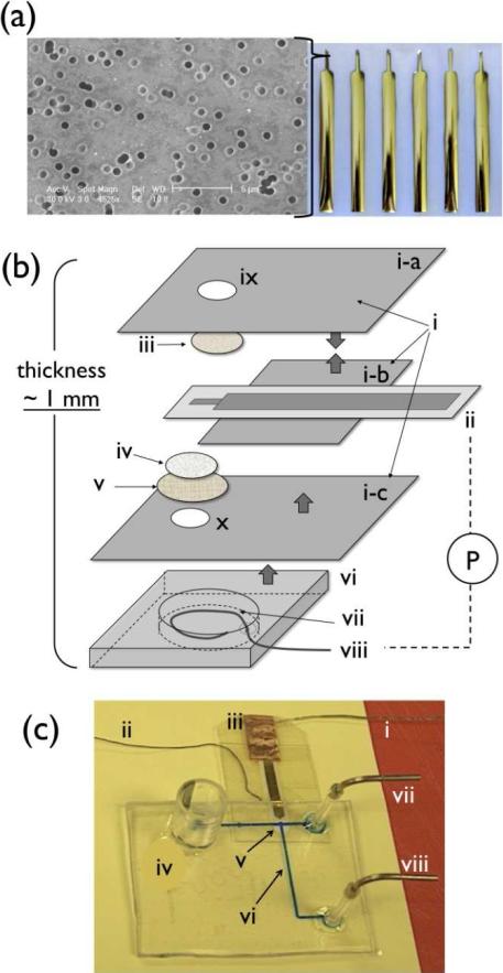
To prepare pAu/ITO electrodes, ITO and Au layers were sequentially vacuum sputtered on a track-etched Nuclepore® membrane with a laser-cut metal stencil mask (100 μm thick, custom-made from I-Source, Inc., Lake Forest, CA). The deposition process was controlled to obtain a total thickness of 300-nm (100-nm and 200-nm for ITO and Au layers, respectively). The narrow tip region served as the WE as shown in Figure 1a. This WE area was further modified to electrochemically deposit Au-HCF (gold-hexacyanoferrate, a Prussian Blue deposition) layer on pAu/ITO by cycling the applied potential 40 times from 0 ~ 1.0 V (vs. Ag/AgCl) in a solution containing KAuCl4, K3Fe(CN)6 (1 mM each) and KNO3 (0.1 M) at pH 3.2 as described elsewhere.15 Growth of Au-HCF layer and oxidation of NO on this modified patterned electrode was examined via a potentiostat (CHI800B, CH Instruments Inc., Austin, TX) with liquid junction reference electrode (RE, Ag/AgCl, MF-2052, Bioanalytical Systems Inc., West Lafayette, IN) and a Pt counter electrode (CE). The concentration of NO was varied by adding aliquots of the NO stock solution into 10 ml of electrolyte (0.1 M KCl, 0.01 M HCl) into which the WE, RE and CE were placed together.5
Figure 1.
(a) Array of Au/ITO electrode patterned on Nuclepore® membrane and SEM image of electrode surface, (b) Schematic drawing of NO sensor components (not in scale, thick arrows indicate adhesive side); i) PE® insulating tape; ii) pAu/ITO electrode; iii) TeflonAF®-treated Celgard® membrane; iv) Nuclepore® membrane; v) Durapore® membrane filter; vi) HybriWell® chamber; vii) KCl/HCl internal solution; viii) Ag/AgCl wire; ix) a hole on (i-a) for GPM exposure to sample; x) a hole on (i-c) for contact to internal electrolyte; two electrodes, (ii) and (viii), are connected to potentiostat (P), (c) image of microfluidic NO detector; i) a lead connected to WE; ii) Ag wire from Ag/AgCl pseudo-RE; iii) Cu conducting tape for electrical contact between WE and a lead; iv) waste reservoir; v) sensing region where GPM of NO sensor exposed through a hole (x); vi) cell culture area on microchannel; vii) inlet for calibration solution; viii) inlet for culture media.
Fabrication of NO Sensor with Thin Planar Configuration and Performance Tests
The new NO sensor was prepared as illustrated in Figure 1b. First, a circular piece of Celgard® membrane (2-mm d., iii, as labeled in Figure 1b) was attached to the adhesive side of polyester (PE) tape (i-a) (8911, 3M, St. Paul, MN) over a punctured area (1-mm d., ix). Then, its surface was coated with a TeflonAF® solution (0.1 μL/mm2). This membrane (iii) serves as the GPM and faces directly toward the surface of the modified pAu/ITO electrode (ii). Another piece of PE tape (i-b) was added to insulate the non-sensing region of the WE from electrolyte, but the back of the sensing area was exposed for electrolyte contact. The roles of the two additional membranes (iv, v) are to provide electrical contact between electrodes by absorbing internal electrolyte from the backside to the WE area and stabilize the WE half-cell configuration. The resultant WE half-cell assembly forms a thin configuration (~ 300 μm, see Supporting Information S1a). External electrical contact of WE was achieved via use of Cu conducting tape (1182, 3M, St. Paul, MN). Finally, adhesive-backed HybriWell™ sealing chamber (HBW13, Grace Bio-Labs, Inc., Bend, OR) was attached to the backside of WE half-cell, where internal solution (0.1 M KCl, 0.01M HCl) and surface oxidized Ag wire (Ag/AgCl pseudo-RE) were incorporated inside the chamber and sealed with silicone rubber adhesive to complete the stand-alone thin film electrochemical system (see Supporting Information S1b for cross-sectional scheme of fully assembled NO sensor).
Basic performance (e.g., sensitivity to NO, selectivity, long-term stability) of the NO sensor described above was examined in 50 mL buffer solution (PBS, pH 7.3) as described elsewhere.5 During the long-term stability test the sensors were kept in unstirred PBS solution under ambient conditions. Then, they were periodically used for calibration with NO(g) stock solution to assess their sensitivity changes over time. In addition, control NO sensors prepared using unmodified pAu/ITO electrodes were also tested to evaluate the effect of the Au-HCF layer. All sensors were polarized at +0.75V vs. Ag/AgCl for at least 4 h before use, and all subsequent amperometric measurements were carried out using the same applied potential.
Fabrication of Microfluidic Devices with Flow-Through NO Detector
The PETG/PU-based microfluidic platform was prepared based on the methodology previously developed (see Supporting Information S2 for the schematic procedure).14 Channels within the final device have dimensions of 400-μm in width and 80-μm in height and the overall device size is 30 mm × 40 mm, as shown in Figure 1c.
To integrate the planar electrochemical NO sensor to the microfluidic device, the PU film at T-intersection of the channel was punctured with a biopsy punch (1-mm o.d.), and the GPM side of the sensing device was placed flush against this hole. Bonding between the bottom PU surface of device and sensor was accomplished with a double-sided adhesive tape (444, 3M, St. Paul, MN), which also has the same size hole for exposure of sensor's sensing region to solution in the microchannel. For calibration of devices in a flow-through arrangement, a series of calibration solutions with different NO concentrations were prepared by diluting an NO stock solution in argon-purged buffer solution (PBS, pH 7.3). A glass body syringe, a multi-channel syringe pump and a 3-way stopcock were then used to alternately deliver the solutions within the channel of the device.
RAW Cell Culture and Cell Seeding in Devices
RAW264.7 cells (Mouse leukemic monocyte macrophage cell line) were cultured and seeded into the microfluidic devices by using the same protocol as described in previous studies with minor modifications.14 Before seeding cells, the channels within the UV-sterilized devices were treated with fibronectin (100 μg/ml, F2006, Sigma) for 30 min to promote cell attachment. Then, a concentrated cell suspension was directed into the desired location inside the micro-device by pulling the solution toward the opposite port via siphon-gravity action. The cells were given 2-4 h to attach under zero flow conditions in a dry heat incubator at 37 °C and an atmosphere of 5% CO2. Pumping of culture media was started after the cells became adherent on the PU membrane. A syringe pump was used for perfusion of the cells within the channel at 3.0 μL/min flow rate with DMEM media.
After the cell layer became confluent within the channel (typically after 4 or more days) the NO sensor was affixed to the device as described above. The free-standing sensor strips were pre-calibrated in bulk PBS buffer solution to check their performance beforehand. A post-calibration was separately conducted in a flow-through setting as described above with NO solution in PBS after the measurement of NO from cell culture and used to calculate the detected NO levels from the measured amperometric signals. Nitric oxide production from the immobilized cells was monitored with desired media, e.g., ones containing lipopolysaccharide (LPS), aminoguanidine (AG), or both in DMEM solution without phenol red and serum (21063, Invitrogen, Carlsbad, CA).
Results & Discussion
Electrode Design for the Thin Planar NO Sensor
To impart the desired catalytic property to the patterned electrodes, a multi-layered structure of ITO, Au and AuHCF was sequentially created on a porous polymer membrane. An ITO layer was chosen not only as a connective layer between polymer substrate (Nuclepore® membrane) and the subsequent Au layer, but also as a conductive yet inert base layer for further modification. A challenge with solely using ITO as WE, however, is that high over-potentials (> ~ + 0.95 V) are needed in order to obtain concentration dependent-limiting current for NO oxidation (data not shown). Hence, the additional Au layer was introduced on the ITO surface followed by further electrodeposition to form an AuHCF layer as the outermost surface of the patterned electrode. In fact, crystalline metal-HCF precipitates on electrodes have been widely studied due to their charge transfer and catalytic properties that facilitate redox reactions of various substrates such as hydrogen peroxide.16 In this study, an electrodeposition method was used to create the AuHCF film via cyclic voltammetry. During this process, the AuHCF films were spontaneously electrodeposited on the Au surface in 1 mM of 1:1 K3[Fe(CN)6]/KAuCl4 solution (see Supporting Information Fig. S3).15
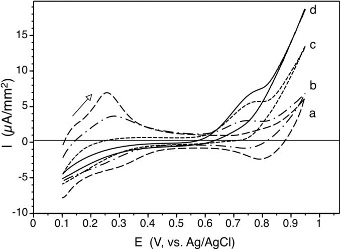
As shown in Figure 2, such electrodes are capable of oxidizing NO at considerably lower potentials, starting from + 0.6 V and show a clear peak potential for oxidative current at ca. + 0.75 V. Separate studies implemented with a Au-disk electrode showed that such an oxidative current wave also appears near + 0.75 V even on a bare Au electrode, but with much less current density (see Supporting Information Fig. S4 (a) and (b)). Moreover, when nitrite solution is used instead of NO solution, this first wave is absent, but the similar large current wave appears at the higher potential region (> + 0.8 V) (see Supporting Information Fig. S4 (b) and (c)). Taken together, we hypothesize that both the top AuHCF layer and the base Au electrode participate in catalytic oxidation of NO to nitrite at + 0.75 V. In contrast, at the higher applied potentials, NO and nitrite may fully oxidize to nitrate on the electrode surface. However, details of the exact electrochemistry remains to be further investigated. This potential (+ 0.75 V vs. Ag/AgCl) that gives high catalytic efficiency together with high selectivity for NO oxidation is chosen as the applied potential for amperometric NO detection throughout this study.
Figure 2.
Cyclic voltamograms of pAu/ITO electrode modified to possess AuHCF on top surface at various NO concentrations in KCl/HCl (0.1 M/0.01 M) solution; a) in the absence of NO; b) 20 μM; c) 100 μM; d) 350 μM at scan rate, 50 mV/s.
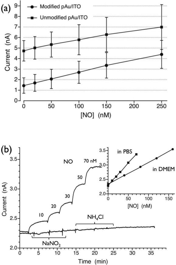
The use of a patterned Au/ITO electrode on a track-etched thin polymer membrane (Nuclepore®) offers two advantages. First, even electrical contact throughout the WE surface is achieved via the open pore structure of the membrane. As shown in the SEM image (see Figure 1a), the deposited Au/ITO layer does not block the pore openings on the membrane surface and can make contact with the internal solution provided through the porous structure. Second, the physical flexibility of the WE enables very close positioning of the active electrode layer to the inner surface of the GPM where analyte, i.e., NO, permeates to the WE. The shortened diffusion path of NO from the GPM to the WE surface helps to create a steep concentration gradient of NO and enhance the overall sensor sensitivity as evidenced in Figure 3 (see below).
Figure 3.
(a) Comparison of NO calibration curves for NO sensors constructed with and without AuHCF layer on WE, (b) NO sensor response curves exhibiting selectivity over nitrite and ammonia; both species added three times separately; 1, 2 and 3 mM concentrations were obtained after each injection; inset) NO calibration plots in two different media.
Performance of Planar NO Sensors with Thin Layer Configuration
Use of a patterned WE enables the construction of a very thin WE half-cell assembly (see Supporting Information Fig. S1a). Further, as illustrated in Figure 1b, a stand-alone NO sensor can be readily fabricated via an adhesive-based bonding method to secure the basic components of electrochemical cells (i.e., WE, RE, internal electrolyte and GPM) in a compact arrangement. The basic performance, e.g., sensitivity, selectivity and stability, of such stand-alone NO sensor was examined in 50-mL buffer in a beaker at room temperature under various conditions.
(a) Sensitivity
The sensitivity of the gas sensors was determined from the slope of calibration plots for each sensor system. In order to identify the influence of the AuHCF layer on sensitivity, NO sensors based on unmodified pAu/ITO electrode (control) were compared to the sensors based on AuHCF modified electrodes. Interestingly, as summarized in Figure 3a, these two types of sensors exhibit similar sensitivities (~ 10 pA/nM). However, the control sensors display higher background currents (as shown in Figure 3a) as well as larger noise in the current signals (data not shown). Hence, sensors possessing AuHCF layer on the WE exhibit a lower limit of detection, i.e., ~ 1 nM NO (see also the raw current readout in Figure 3b). It is likely that the AuHCF layer promotes adsorption and oxidation of NO (see Supporting Information Fig. S4), and also increases the applied potential required for the WE to oxidize electroactive impurites present within the internal electrolyte solution.
(b) Selectivity
As shown in Figure 3b, nitrite and ammonia do not influence the amperometric signal for NO detection unless their concentrations are at mM levels. Similarly, high selectivity is also observed over other ionic species such as ascorbate, glutathione, etc. (see Supporting Information Table S1). As illustrated within the inset graph of Figure 3b, even in DMEM cell culture media (without serum) there is minimal change in the sensor's background current, which demonstrates that the sensors exhibit satisfactory selectivity to function in biological samples. However, the observed sensitivity decreases in DMEM as compared to that in PBS (inset of Figure 3b). This is due to the rapid decay of NO by components in DMEM rather than any absolute reduction of sensor sensitivity since sensor performance returns to original levels when detection of NO is made in PBS (data not shown).
It is clear that the GPM (i.e., TeflonAF®-treated Celgard® membrane) performs as effectively as the porous poly(tetrafluoroethylene) (PTFE) membrane coated with TeflonAF® reported previously.11 Nitric oxide readily passes through such materials via partitioning into its hydrophobic polymeric matrix,13, 17 except for other oxidizable interferents such as ammonia.11 In addition, the TeflonAF®-treated Celgard® membrane affixed on adhesive-backed polymer film serves as a seal to separate the sample phase from the inner electrolyte.
(c) Stability
The sensor exhibits useful responses for up to 4 weeks (with sensitivity between 4 ~ 12 pA/nM and limit of detection < 10 nM). The sensitivity does gradually decay over time, with a particularly pronounced decrease after one week (see Supporting Information Figure S5). Current noise levels are also found to gradually increase (data not shown). Such degradation of sensor performance may be attributable to slow dissolution of the patterned Au electrode in the presence of chloride ion and electrode fouling over time due to the continued oxidation of impurity molecules supplied from the sample and internal solutions.
Device Fabrication and Flow-through NO Detection
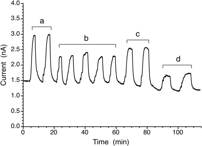
To preserve the NO level in small volumes of sample within a microfluidic-platform, we utilized low gas-permeable PU-PETG microfluidic devices.14 Hence, the planar film type NO sensor was integrated to an opening of the PU film underneath microchannels as shown in Figure 1c and its response was monitored with flow of buffer solution containing NO(g). As shown in Figure 4, the device can reversibly detect NO at nM levels under various flow conditions. At high flow rate (> 100 μL/min), amperometric sensitivity of the microfluidic NO detector (nM) is comparable to that of macroscopic bulk phase NO measurement. At slower flow rates, NO depletion in the small fluid volumes due to the consumption of NO by the sensor results in smaller signals.
Figure 4.
Amperometric response of microfluidic NO detector with flowing test solutions containing different levels of NO, flow rate, 50 μL/min, a) 350 nM; b) 100 nM; c) 200 nM; b) 40 nM.
Real-time Detection of NO from Cell Culture within Microfluidic Devices
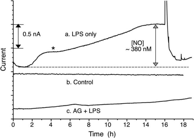
The hard top (PETG)-soft bottom (PU) microchannel device used in this study is cell culture compatible, as described in a previous report.14 Macrophage type cells were cultured (see Supporting Information Fig. S6) in the microfluidic device equipped with the new NO detector. Stimulation of cells with LPS (1 μg/mL in DMEM media) led to a relatively steep initial increase of extracellular NO concentration, followed by a gradual increase over an ~ 18 h period to ~ 350 nM (see Fig. 5). Detection of such high levels of NO with such few cells is made possible by direct integration of the NO sensor with microchannels and by use of low gas permeable materials to construct the channels. At the relatively slow flow rate of media used in this study (3 μL/min) it is estimated that the longest travel time for NO produced by cells to reach the planar sensor is about 80 s. This is within the reported lifetime of NO (~ 200 s) in deoxygenated buffers.4, 9 The sensing capability is reversible; the detector's current readout returns to original background levels when the cell-conditioned media is replaced with fresh media. These real-time, reversible NO detection capabilities using small numbers of cells in a reagent and media economic manner is expected to be useful for a broad range of NO studies.
Figure 5.
Three different measurements of real-time NO detection from RAW264.7 cells grown on NO detector device, a) 1.0 μg/mL LPS; b) without LPS; c) 1.0 μg/mL LPS and 100 μM AG in DMEM; flow rate of DMEM: 3.0 μL/min. For each measurement cells were confluent within the device channel.
Nitric oxide production from macrophages studied here is one of the early defensive mechanisms against microbial infection. Endotoxins (e.g., LPS) secreted from bacterial intruder cells or cytokines from immune responsive cells can trigger upregulation of inducible NOS (iNOS) expression and mass production of NO. It is known that the time required for full expression of iNOS to yield large amounts of NO production is about 4-6 h.18 As expected, such NO production profile can be recorded in real-time with the microfluidic device described in this paper (see first plateau (*) on trace (a) in Figure 5). When aminoguanidine (AG), a relatively selective iNOS inhibitor, is added to the DMEM media along with LPS, initial NO production is found to be largely blocked; however, NO production still slowly increases over time even with AG present. This could be due to the action of another NOS isoform, e.g., constitutive endothelial NOS in macrophages19 or degradation of AG over the time period.
Conclusion
We successfully developed a microfluidic NO detection system using a new thin film sensor where all electrochemical components are assembled in a multilayered, planar structure. Of particular note is the use of a patterned WE (pAuHCF/Au/ITO electrode) prepared on a porous polymer membrane and a special GPM (i.e., TeflonAF®-treated Celgard® membrane). The use of these materials leads to high sensitivity for NO detection (typically, > 10 pA/nM) and high selectivity against most common interferents (nitrite, ammonia, etc.) found in biological samples. We further demonstrated that LPS-induced NO production from small numbers of macrophage cells can be monitored in real time directly from media flowing within the cell culture microchannels of the PETG-PU device. With increasing importance of NO in multiple biological processes, such as infection, cardiovascular disease and pulmonary disease,20 coupled with advances in constructing microfluidic models of various parts of the body beyond the macrophage system shown here, e.g., the vascular or pulmonary model systems,21 we anticipate that the NO sensor embedded microfluidic cell culture systems will be broadly useful for mechanistic studies and drug testing.
Supplementary Material
Acknowledgement
The authors gratefully acknowledge the NIH (EB-00783, EB-004527, and HL-084370) and the Coulter Foundation for supporting this work.
References
- 1.Kiss JP. Brain Res. Bullet. 2000;52:459–466. doi: 10.1016/s0361-9230(00)00282-3. [DOI] [PubMed] [Google Scholar]; Nathan C, Shiloh MU. Proc. Nat. Acad. Sci. U. S. A. 2000;97:8841–8848. doi: 10.1073/pnas.97.16.8841. [DOI] [PMC free article] [PubMed] [Google Scholar]; Radomski MW, Palmer RMJ, Moncada S. Proc. Natl. Acad. Sci. U.S.A. 1990;87:5193–5197. doi: 10.1073/pnas.87.13.5193. [DOI] [PMC free article] [PubMed] [Google Scholar]
- 2.Heiss C, Lauer T, Dejam A, Kleinbongard P, Hamada S, Rassaf T, Matern S, Feelisch M, Kelm M. J. Am. Colleg. Cardiol. 2006;47:573–579. doi: 10.1016/j.jacc.2005.06.089. [DOI] [PubMed] [Google Scholar]; Rassaf T, Kleinbongard P, Kelm M. Kidney. Blood Press. Res. 2005;28:341–348. doi: 10.1159/000090188. [DOI] [PubMed] [Google Scholar]; Pacher P, Beckman JS, Liaudet L. Physiol. Rev. 2007;87:315–424. doi: 10.1152/physrev.00029.2006. [DOI] [PMC free article] [PubMed] [Google Scholar]; Stamler JS. Circ. Res. 2004;94:414–417. doi: 10.1161/01.RES.0000122071.55721.BC. [DOI] [PubMed] [Google Scholar]
- 3.Feelisch M, Stamler JS. Methods in Nitric Oxide Research. John WIley; Chichester, UK: 1996. [Google Scholar]
- 4.Thomas DD, Liu X, Kantrow SP, Lancaster JR. Proc. Nat. Acad. Sci. U. S. A. 2001;98:355–360. doi: 10.1073/pnas.011379598. [DOI] [PMC free article] [PubMed] [Google Scholar]
- 5.Lee Y, Oh BK, Meyerhoff ME. Anal. Chem. 2004;76:536–544. doi: 10.1021/ac035064h. [DOI] [PubMed] [Google Scholar]
- 6.Malinski T, Taha Z. Nature. 1992;358:676–678. doi: 10.1038/358676a0. [DOI] [PubMed] [Google Scholar]
- 7.Zhang X, Cardosa L, Broderick M, Fein H, Lin J. Electroanalysis. 2000;12:1113–1117. [Google Scholar]
- 8.Spence DM, Torrence NJ, Kovarik ML, Martin RS. The Analyst. 2004;129:995–1000. doi: 10.1039/b410547h. [DOI] [PubMed] [Google Scholar]; Hulvey M, Martin R. Anal. Bioanal. Chem. 2009;393:599–605. doi: 10.1007/s00216-008-2468-z. [DOI] [PMC free article] [PubMed] [Google Scholar]
- 9.Kotsis DH, Spence DM. Anal. Chem. 2002;75:145–151. doi: 10.1021/ac0258249. [DOI] [PubMed] [Google Scholar]
- 10.Cha W, Anderson MR, Zhang F, Meyerhoff ME. Biosens. Bioelectron. 2009;24:2441–2446. doi: 10.1016/j.bios.2008.12.022. [DOI] [PMC free article] [PubMed] [Google Scholar]; Cha W, Lee Y, Oh BK, Meyerhoff ME. Anal. Chem. 2005;77:3516–3524. doi: 10.1021/ac048192u. [DOI] [PubMed] [Google Scholar]; Shin JH, Privett BJ, Kita JM, Wightman RM, Schoenfisch MH. Anal. Chem. 2008;80:6850–6859. doi: 10.1021/ac800185x. [DOI] [PMC free article] [PubMed] [Google Scholar]
- 11.Cha W, Meyerhoff ME. Chem. Anal. (Warsaw) 2006;51:949–961. [Google Scholar]
- 12.Massey LK. Permeability and Other Film Properties of Plastics and Elastomers: A Guide to Packaging and Barrier Materials. 2nd ed. William Andrew Inc.; Norwich, NY: 2003. [Google Scholar]
- 13.Shaw AW, Vosper AJ. J. Chem. Soc., Faraday Trans. 1. 1977;73:1239–1244. [Google Scholar]
- 14.Mehta G, Lee J, Cha W, Tung Y-C, Linderman JJ, Takayama S. Anal. Chem. 2009;81:3714–3722. doi: 10.1021/ac802178u. [DOI] [PubMed] [Google Scholar]
- 15.Kumar SS, Joseph J, Phani KL. Chem. Mat. 2007;19:4722–4730. [Google Scholar]
- 16.Karyakin AA. Electroanalysis. 2001;13:813–819. [Google Scholar]
- 17.Liu X, Miller MJS, Joshi MS, Thomas DD, Lancaster JR. Proc. Nat. Acad. Sci. U. S. A. 1998;95:2175–2179. doi: 10.1073/pnas.95.5.2175. [DOI] [PMC free article] [PubMed] [Google Scholar]
- 18.Stuehr DJ, Marletta MA. Proc. Nat. Acad. Sci. U. S. A. 1985;82:7738–7742. doi: 10.1073/pnas.82.22.7738. [DOI] [PMC free article] [PubMed] [Google Scholar]; Braulio VB, Ten Have GAM, Vissers YLJ, Deutz NEP. Am. J. Physiol. Endocrinol. Metab. 2004;287:E912–918. doi: 10.1152/ajpendo.00540.2003. [DOI] [PubMed] [Google Scholar]
- 19.Miles PR, Bowman L, Rengasamy A, Huffman L. Am. J. Physiol. Lung. Cell. Mol. Physiol. 1998;274:L360–368. doi: 10.1152/ajplung.1998.274.3.L360. [DOI] [PubMed] [Google Scholar]; Connelly L, Jacobs AT, Palacios-Callender M, Moncada S, Hobbs AJ. J. Biol. Chem. 2003;278:26480–26487. doi: 10.1074/jbc.M302238200. [DOI] [PubMed] [Google Scholar]
- 20.Elahi MM, Naseem KM, Matata BM. FEBS Journal. 2007;274:906–923. doi: 10.1111/j.1742-4658.2007.05660.x. [DOI] [PubMed] [Google Scholar]; Ricciardolo FLM. Thorax. 2003;58:175–182. doi: 10.1136/thorax.58.2.175. [DOI] [PMC free article] [PubMed] [Google Scholar]; Tripathi P, Tripathi P, Kashyap L, Singh V. FEMS Immunol. Med. Microbiol. 2007;51:443–452. doi: 10.1111/j.1574-695X.2007.00329.x. [DOI] [PubMed] [Google Scholar]
- 21.Huh D, Fujioka H, Tung Y-C, Futai N, Paine R, Grotberg JB, Takayama S. Proc. Nat. Acad. Sci. U. S. A. 2007;104:18886–18891. doi: 10.1073/pnas.0610868104. [DOI] [PMC free article] [PubMed] [Google Scholar]; Song JW, Gu W, Futai N, Warner KA, Nor JE, Takayama S. Anal. Chem. 2005;77:3993–3999. doi: 10.1021/ac050131o. [DOI] [PubMed] [Google Scholar]
Associated Data
This section collects any data citations, data availability statements, or supplementary materials included in this article.


