Abstract
We introduce the use of a birefringent crystal with lensless digital holography to create an on-chip differential interference contrast (DIC) microscope. Using an incoherent source with a large aperture, in-line holograms of micro-objects are created, which interact with a uniaxial crystal and an absorbing polarizer, encoding differential interference contrast information of the objects on the chip. Despite the fact that a unit fringe magnification and an incoherent source with a large aperture have been used, holographic digital processing of such holograms rapidly recovers the differential phase contrast image of the specimen over a large field-of-view of ~24 mm2.
OCIS codes: (090.1995) Digital holography, (180.3170) Interference microscopy, (170.3880) Medical and biological imaging
1. Introduction
Together with Zernike’s phase contrast microscopy concept [1], differential interference contrast (DIC) microscopy, also known as Nomarski microscopy [2], has been widely used to enhance the contrast of transparent phase objects that are harder to image with conventional bright field microscopes [3]. Both of these approaches essentially convert the phase information of the sample into amplitude or intensity modulation through the use of phase structures or birefringent crystals [1,2]. Over the last few years, a number of different DIC imaging approaches have also been introduced that do not use a birefringent crystal. One example is based on aperture interference [4], where the regular microscope image of a sample is mechanically scanned over a structured aperture which acts as a wavefront sensor. Another major DIC approach relies on conventional digital holography [5–11], where the phase maps of the specimen can be reconstructed to create DIC equivalent images. Such digital approaches, however, rely on post-processing of the reconstructed phase information rather than physical detection of differential interference holograms.
In this manuscript, we demonstrate the use of a birefringent crystal with lensless digital holography to introduce an on-chip microscope that can create DIC images of micro-objects over a large field of view (FOV) of ~24 mm2. Unlike digital reconstruction based holographic DIC approaches discussed above, the use of a thin birefringent crystal physically creates differential interference holograms at the sensor plane that encode the spatial phase variation of the sample into amplitude oscillations. This modulation process can be physically controlled by varying the crystal thickness, independent of the spatial resolution of the holographic system. In addition, as we will further illustrate with experimental results, this DIC amplitude modulation with a sub-pixel physical shear distance leads to enhancement in contrast and sharpness of the reconstructed holographic images. Another important difference in the presented DIC approach is that it does not utilize any lenses, coherent sources such as lasers or any mechanical scanning.
Before we discuss the details of this on-chip DIC imaging approach that is based on lensless in-line holography and present DIC images of various micro-objects, let us briefly go over, in the next section, some of the non-conventional aspects of our hologram recording geometry that enables the use of a birefringent crystal to create DIC images over a large FOV. Finally we would like to also note that the use of birefringent crystals in holographic imaging [12] or wavefront sensing [13] has also been demonstrated but these techniques were not applied to DIC microscopy.
2. Lensless on-chip microscopy based on incoherent digital holography
Here we briefly discuss non-conventional aspects of our hologram recording geometry. To start with, for the illumination, we use a spatially incoherent source emanating from a relatively large aperture (with a diameter of e.g., D ~ 100λ – see Fig. 1 ) which creates a limited coherence diameter (RC) at the object plane (such that RC2 << FOV). In practice, the finite physical distance between the incoherent source and the aperture would create partial coherence at the aperture plane to effectively increase RC at the object plane. However, this partial spatial coherence at the aperture plane is not a requirement for our recording geometry (Fig. 1). In other words, even if a perfectly incoherent field filled the large aperture, the free space propagation between the aperture and the object planes would create a sufficiently large spatial coherence diameter for each micro-object within the imaging field-of-view. The advantages of such a large incoherent aperture are several folds: (i) it permits significant reduction of the speckle noise; (ii) the undesired coherent cross-talk among micro-objects of the same FOV is greatly reduced; and (iii) the light throughput of the aperture is significantly increased making the alignment of the in-line holographic imaging system much simpler.
Fig. 1.
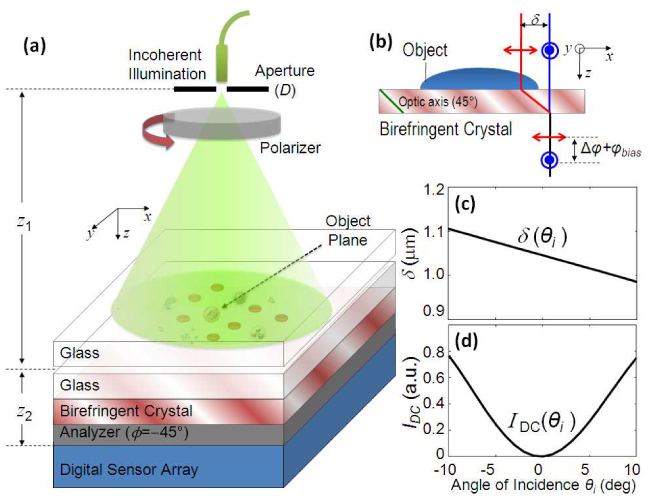
DIC microscopy by lensless holographic imaging: (a) Holographic on-chip DIC microscopy setup using incoherent illumination with a large aperture (diameter D ~50-100 µm) and a uniaxial birefringent crystal together with z1 >> z2 (typically z1~5-10 cm and z2~1mm); (b) Differential phase interference due to double refraction phenomenon by a thin birefringent crystal plate (e.g., thickness ~0.18 mm). Angular sensitivity of the shear distance (δ) and the DC background intensity IDC are illustrated in (c) and (d), respectively. Note that the orientation of the first polarizer is adjusted to control the differential phase contrast while the second polarizer (i.e., the analyzer) is fixed at −45° with respect to the crystal orientation. Cross-polarizer and parallel polarizer configurations can be made equivalent to each other in terms of achieving optimum DIC performance, depending on the phase bias term to be even or odd multiples of π, respectively (refer to Section 3).
For conventional lensless in-line holography geometries which typically utilize a fringe magnification (F) of >5-10 [14–18], such a large incoherent aperture would imply an unacceptable resolution loss for the reconstructed images. Not to be penalized by the same resolution loss, here we utilize unit fringe magnification (F ≈1) by placing the sample plane much closer to the sensor array than to the incoherent source [i.e., z1 >> z2 and F = (z1+z2)/z1 ≈1, see Fig. 1(a)]. With this hologram recording geometry, the large aperture of the incoherent source now gets scaled at the sensor plane by a demagnification factor of M = z1/z2, which is typically ~100, eliminating the limiting effect of the large incoherent aperture on spatial resolution. To be more precise, under spatially incoherent illumination as in Fig. 1, it can be theoretically shown that a de-magnified (by M fold) version of the aperture function is convolving the holographic diffraction terms at the sensor array, and since in our recording geometry we utilize M ~100, the filtering effect of a large aperture function on spatial frequency content of the holographic diffraction terms is almost entirely removed. The same choice (M >> 1 and F ≈ 1) also permits us to image a significantly larger FOV claiming the entire digital sensor area as our microscopic imaging FOV.
These advantages of our recording geometry are balanced by an important trade-off, i.e., the pixel size at the sensor array now becomes a limiting factor. A large fringe magnification, as typically practiced in lensless in-line holography [14,15,18] ensures that the effective pixel size during hologram recording is reduced by the same amount, F, which enables successful recording of fringes that carry high spatial frequencies (over a smaller sample FOV that is now reduced by ~F 2 when compared to the sensor area). For instance, by using a high-index oil (n = 1.5) to replace air, together with F > 35, it is feasible to achieve sub-micron resolution at ~500 nm illumination with lensless digital in-line holography [18].
Despite this important limitation of the pixel size, in the presented hologram recording geometry of Fig. 1(a), with F~1 and a large incoherent aperture of ~50 µm, we manage to achieve sub-pixel spatial resolution (<1.5 μm with λ ~ 470 nm and a pixel size of 2.2 μm – see Suppl. Figures 5-7 in Appendix) through iterative processing of the acquired holograms without any paraxial approximations.
3. Differential interference contrast (DIC) imaging using incoherent lensfree holography
After going through the basics of our non-traditional holographic recording scheme, let us now introduce the implementation of our lensless DIC microscope based on in-line digital holography using a birefringent crystal. Because in our recording scheme (Fig. 1) each micro-object is “effectively” illuminated with a spatially coherent plane wave (over the extent of the object), the scattered fields coherently propagate a distance of z2 (typically ~1 mm). To achieve differential interference contrast imaging, a thin birefringent crystal (e.g., ~180 μm thick quartz plate), whose optic axis is at 45° with respect to the propagation direction (z-axis), is inserted underneath the object plane as shown in Figs. 1(a), 1(b). In the following analysis, we will only consider normal incidence to the birefringent crystal and ignore the angular spectrum of the complex field entering the crystal, which will be left as a topic to further expand in the next Section #4. As a result of the double-refraction phenomenon, as soon as the complex object wavefronts enter the crystal, they split into two components corresponding to the ordinary and the extra-ordinary waves, which have orthogonal polarizations. At the exit of the crystal, these two complex wavefronts propagate parallel to each other with a lateral shift (δ), also known as the shear distance in conventional DIC microscopy. Since the effective coherence diameter at the object plane is much larger than the shear distance, these two waves are coherent to each other but they carry information of slightly different points of the object, which leads to the differential interference contrast operation. Two aligned polarizers (i.e., parallel or crossed linear polarizers) are used to create interference between these two orthogonal waves. The hologram as a result of this interference is sampled by the digital sensor array. The reconstructed image of this digital hologram, under appropriate imaging conditions, contains the differential phase contrast information of the sample.
To better understand the theory behind the presented approach, let us assume a randomly polarized incoherent quasi-monochromatic field entering a linear polarizer oriented at an adjustable angle of ϕ from the x-axis [see Fig. 1(a)]. Because our recording geometry involves a large z1, this incoherent field, before interacting with the sample, picks up spatial coherence sufficient to record holograms of each micro-object at the sensor plane. After interacting with the micro-object, this wave will create a complex wavefront of each object, i.e., . For simplicity we assume no birefringence for the object, and even if there was some birefringence, it is relatively straight-forward to eliminate its effect by placing the 1st polarizer after the sample plane, i.e., right above the uniaxial crystal [see Fig. 1(a)]. Such a change would not affect the operation principles of our lensless DIC microscope, and the following theoretical analysis and its conclusions would still apply. Note also that because of the limited coherence diameter at the object plane, this analysis is only applicable to the extent of individual objects. This mismatch between the coherence diameter and the imaging FOV is also the reason why there is no longer a direct Fourier transform relationship between the object and the hologram planes. In other words, the phases of different regions of the imaging field of view are not correlated with each other due to limited spatial coherence at the object plane. However, this does not constitute any challenges since the digital reconstruction of the entire FOV can still be achieved all in parallel within <1 sec using a graphics processing unit (GPU; e.g., NVIDIA GeForce GTX 285) through iterative processing which involves going back and forth between the object and sensor planes, while enforcing the object support and the transfer function of free-space at each step [19–21].
As the linearly polarized object wavefront, , propagates through a uniaxial crystal, whose optic axis lies in the x-z plane, aligned at 45° with respect to the z-axis (Fig. 1), it experiences double refraction as a result of which the two orthogonal polarization components are split by a small shear distance, i.e., , where no and ne are the ordinary and extra-ordinary indices of refraction, respectively, and t is the thickness of the crystal plate. Without loss of generality, we will limit our derivations to positive birefringent crystals where ne > no. After the crystal plate, the outgoing wave can be written as: , where z = z1 defines the exit plane of the crystal, is the phase bias, λ is the wavelength of light, and OPD is the optical path length difference between the ordinary and extraordinary waves, given by (where ). Therefore, at the exit of the uniaxial crystal, the ordinary and extra-ordinary waves are separated in space by a shear distance of δ, and their interference encodes the spatial phase variation of the sample into amplitude oscillations.
Towards this end, let us assume that a second linear polarizer (i.e., the analyzer) is placed at −45° from the x-axis in the x-y plane [see Fig. 1(a)]. If the object is mainly a phase object, i.e., , then intensity of the transmitted wave at the exit plane of the analyzer (at z = z2) becomes: , where is the phase difference between two positions (x and x-δ) of the complex wavefronts. For achieving maximum differential phase contrast, the effect of the phase bias term (φbias) should be minimized. For this end, let us first consider φbias = 2mπ where m is an integer and assume that a crossed-polarizer configuration (i.e., ϕ = 45°) is used. Under these hologram recording conditions and for small phase differences i.e., Δφ <<1 (cos(Δφ) ≈1 − Δφ2/2), the amplitude of the resulting complex wavefront can be written as:
| (1) |
Equation (1) indicates that the detected amplitude at the sensor plane is linearly proportional to the differential phase information (Δφ) of the micro-object. Similarly, the same conclusion can also be reached with a parallel-polarizer configuration (i.e., ϕ = −45°) when φbias = (2m+1)π. Therefore, crossed- and parallel-polarizer configurations can be made equivalent to each other (in terms of DIC performance) depending on the phase bias term.
The above analysis indicates that, for a given birefringent crystal thickness, the optimum DIC imaging condition is achieved at specific wavelengths where the effect of φbias is minimized. This phase bias, however, can be canceled by stacking two identical birefringent crystal plates at 90° with respect to each other. For such a double crystal configuration, the same optimum DIC operation can be achieved over a wide range of wavelengths. A minor disadvantage of this approach is an increase in the total crystal length, which then increases the shear distance by 2.
4. Experimental results and discussions
To demonstrate the performance of the above described lensless holographic DIC microscope, we imaged various micro-objects using the experimental configuration shown in Fig. 1. For these experiments we used a CMOS sensor chip (Model: MT9P031, Micron Technology, 5 Mpixels), with a pixel size of 2.2 μm and an active imaging area of 24.4 mm2. For the light source, we utilized a monochromator with a Xenon lamp (Cornerstone T260, Newport Corp.) with a spectral bandwidth (FWHM) of ~15-20 nm. The light from the monochromator was filtered by a 50 μm diameter pinhole, which was placed at ~10 cm above the sample surface. The objects were placed ~1 mm away from the active sensor area such that M ~100 and F ~1.
Under these illumination conditions, lensless digital holograms and their reconstructed DIC images for 5 and 10 μm diameter particles, and white blood cells in a blood smear sample are shown in Fig. 2 . The reconstructed DIC images are also compared against regular bright-field microscope images of the same FOV. For both samples, the DIC images manifest surface relief contrast and shadow cast effects of the micro-objects as a result of the differential interference operation. Figure 3 also illustrates the holograms of microbeads over a large FOV of ~24 mm2 and the reconstructed DIC images at different areas within this FOV.
Fig. 2.
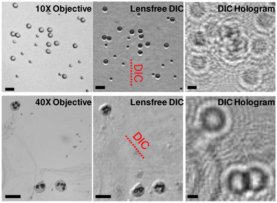
Reconstructed lensless DIC images of micro-objects. Top Row: 5 & 10 μm sized melamine (n = 1.68) beads in a medium (n = 1.524, Norland Optical Adhesive 65). The sample was illuminated at 550 nm (~18 nm FWHM bandwidth). A 50 μm aperture (at z1 = 10 cm) and 0.18 mm-thick quartz plate (δ ~1 μm) were used. Bottom Row: White blood cells in a blood smear sample are imaged. The sample was illuminated at 670 nm (~18 nm FWHM bandwidth) through a 50 μm aperture (z1 = 10 cm) and 0.3 mm-thick quartz plate (δ ~2 μm) was used for the DIC image. The shear directions are indicated in the figures with dashed lines. Conventional bright-field microscope images of the same FOV are presented for comparison. The scale bars are 20 μm.
Fig. 3.
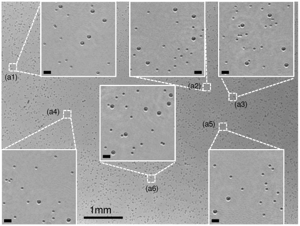
Reconstruction results of lensless DIC microscopy for 5 and 10 µm particles over a wide FOV of ~24 mm2 are demonstrated. The main figure shows the raw holograms of the micro-beads and the sub-figures (a1-a6) show the reconstructed DIC amplitude images at different areas of the FOV. The sample was illuminated at 550 nm (~18 nm FWHM bandwidth) with a 50 µm aperture (z1 = 10 cm). A 0.18mm-thick quartz crystal plate and two absorbing polarizer films were used. The scale bars for the subfigures are 20 μm.
To further demonstrate the contrast enhancement of our lensless DIC images, under the same illumination conditions, we imaged C. elegans samples as illustrated in Fig. 4 . In this figure, we also compared the reconstructed DIC images of the samples against regular holographic images that are obtained with the same setup [Fig. 1(a)], but this time without the use of any polarizers or the birefringent crystal. This figure clearly shows the increased contrast for the fine features of the DIC images [Figs. 4(b), 4(e)] when compared to the regular lensfree images [Figs. 4(c), 4(f)] of the same specimen.
Fig. 4.
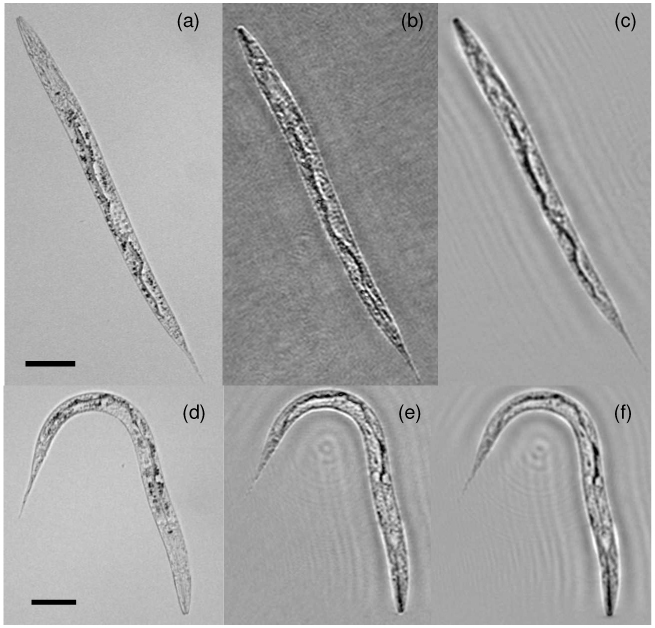
Caenorhabditis elegans imaging: (a) Microscope image (with a 10X objective lens – NA ~0.25); (b) Reconstructed lensfree DIC image; (c) Reconstructed regular lensfree holographic image; (d-f) same as (a-c), except for another C. elegans sample. Imaging conditions are the same as in Fig. 2. The scale bars are 50 μm.
For digital reconstruction of these DIC images from their raw holograms, we applied an iterative phase retrieval algorithm to eliminate the twin image artifact [19–21]. In this approach, we work with the amplitudes of the lensless holograms and recover the 2D phase information of the complex field that was lost during the detection process. Once the entire complex field is recovered, the DIC images of the micro-objects can be obtained through back-propagation of the recovered fields.
As already mentioned earlier, in our theoretical analysis (Section 3) we only considered normal incidence to the birefringent crystal and ignored the angular spectrum of the complex field entering the crystal. However, both δ and Δφbias are sensitive to the incident angle (θi) of the fields that make up the object wavefront. Next, we would like to better understand this angular dependency of the DIC term, and its impact for image quality. For simplicity, we limit our discussions to the case where the optic axis of the crystal lies in the plane of incidence. This is a valid assumption since both δ and Δφbias are most sensitive to the incident angle in this direction. Under this assumption, both δ and the DC field intensity (IDC ~1−cos(Δφbias)) can be analytically expressed as a function of θi [22]. Based on this analytical expression, Figs. 1(c), 1(d) summarize the effect of θi on the shear distance and the strength of the DC term for our hologram recording geometry. Since our holograms are effectively recorded with F ≈1, the DIC image distortion that is caused by such an angular dependency is relatively reduced which is an important reason why our DIC image quality remains quite well across the entire sensor FOV of ~24 mm2 as also indicated in Fig. 3.
5. Conclusions
In conclusion, we have introduced a lensless DIC microscopy modality that is based on the use of a thin birefringent crystal with a novel digital holographic recording geometry. Unlike other DIC imaging techniques based on digital reconstruction of phase maps in conventional digital holography, we utilize double refraction of a birefringent crystal to physically create differential interference holograms at the sensor plane, which could improve both contrast and sharpness of images when compared to the regular holographic images obtained under the same imaging conditions. This on-chip DIC microscopy platform is free from any lenses, microscope objectives, or any mechanical scanning. Further, the presented holography platform does not need a laser, but instead uses a spatially incoherent source with a relatively large spectral bandwidth (~15-20 nm). In addition to using an incoherent source, unlike most other holographic approaches, our technique also does not rely on a small aperture size to increase the spatial coherence at the object plane. The use of a large aperture (e.g., ~50 µm) in lensless holography not only provides a much simpler mechanical interface for light coupling, but also reduces the cross-talk among micro-objects of the same FOV, as well as the speckle noise. Another major advantage of our lensless DIC approach is its significantly increased imaging FOV (which in our case is ~24 mm2) constituting ~10 fold improvement over a conventional 10X objective lens. Despite these advantages, the finite pixel size of the sensor array limits our spatial resolution to be <~1.5 µm at ~470 nm illumination for a pixel size of 2.2µm.
Acknowledgements
The authors acknowledge the support of the Okawa Foundation, Vodafone Americas Foundation, DARPA DSO (under 56556-MS-DRP), NSF BISH program (under Awards # 0754880 and 0930501), NIH (under 1R21EB009222-01 and the NIH Director’s New Innovator Award - Award Number DP2OD006427 from the Office of The Director, National Institutes of Health), AFOSR (under Project # 08NE255) and ONR (under Young Investigator Award 2009).
6. Appendix: Supplementary Figures
Fig. 5.

Supplementary. Reconstruction results of several well-defined micro-objects are illustrated to better quantify the resolution of the presented lensfree incoherent holographic imaging platform. The cross-sectional profiles along the dashed lines are shown on the images. For test feature 1, the FWHM values of the linear gap between the squares are 1.43μm and 0.6μm for the amplitude reconstruction and 40X objective-lens (NA = 0.6) microscope images, respectively. The same gap cannot be resolved by the 10X objective-lens (NA = 0.2). This indicates that the ~0.6 μm wide gap has been imaged with a spatial resolution of <1.5 μm using our incoherent lensfree holography approach. For test feature 2, the FWHM is measured on the cross-section across the letter “L”, and the values for amplitude reconstruction and 40X microscope images are 2.6 μm and 2.0 μm, respectively. The FWHM of the spacing between squares in test feature 3 is 1.80 μm and 1.95μm for amplitude reconstruction and 40X images, respectively. For all test features, we utilized z1 = ~3 cm, z2 = ~0.6 mm, F = ~1, D = 50 µm and spatially incoherent source at λ0=470 nm with a FWHM spectral bandwidth of ~5nm. Exposure time in these experiments was ~25 ms. Scale bars are 5 µm for the reconstructed images as well as their microscope comparisons, and scale bars are 50 μm for the raw holograms on the left column.
Fig. 6.
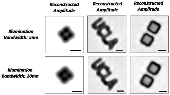
Supplementary. Amplitude reconstruction images are shown for the same test features as in Suppl. Figure 5 using the same incoherent source wavelength (470 nm), pinhole size (50 μm), F ~1, and pinhole-to-cell distance (z1 = ~3cm), with 5 nm and 20 nm source bandwidths. Integration times for the detection are less than 30ms. Scale bars, 5 μm.
Fig. 7.
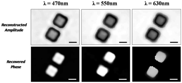
Supplementary. Amplitude and phase reconstruction results of the test features at 470 nm, 550 nm and 630 nm central wavelengths are illustrated. For this experiment, F ~1 and a 50 μm aperture at z1 = ~3cm is utilized. Source bandwidth is kept constant at ~5 nm. Scale bars, 5 μm. Notice that in the recovered phase images, the gap between the squares is imaged to be larger than the recovered amplitude images. The reason for this discrepancy is the fact that for the etched objects on glass, the edges do not obey a phase object criterion as they significantly scatter light, which cast a strong signature in the reconstructed amplitude images, yielding a better estimation of the gap between the square features in the amplitude domain rather than the phase.
References and Links
- 1.Zernike F., “Phase-contrast, a new method for microscopic observation of transparent objects. Part II,” Physica 9(10), 974–986 (1942). 10.1016/S0031-8914(42)80079-8 [DOI] [Google Scholar]
- 2.Nomarski G., “Differential microinterferometer with polarized light,” J. Phys. Radium 16, 9s–13s (1955). [Google Scholar]
- 3.M. Pluta, Specialized Methods, Vol. 2 of Advanced light microscopy (Elsevier, New York, 1989), Chap. 7. [Google Scholar]
- 4.Cui X., Lew M., Yang C., “Quantitative differential interference contrast microscopy based on structured-aperture interference,” Appl. Phys. Lett. 93(9), 091113 (2008). 10.1063/1.2977870 [DOI] [Google Scholar]
- 5.Barone-Nugent E. D., Barty A., Nugent K. A., “Quantitative phase-amplitude microscopy I: optical microscopy,” J. Microsc. 206(3), 194–203 (2002). 10.1046/j.1365-2818.2002.01027.x [DOI] [PubMed] [Google Scholar]
- 6.Ferraro P., Alferi D., De Nicola S., De Petrocellis L., Finizio A., Pierattini G., “Quantitative phase-contrast microscopy by a lateral shear approach to digital holographic image reconstruction,” Opt. Lett. 31(10), 1405–1407 (2006). 10.1364/OL.31.001405 [DOI] [PubMed] [Google Scholar]
- 7.Popescu G., Park Y. K., Badizadegan K., Dasari R. R., Feld M. S., “Diffraction phase and fluorescence microscopy,” Opt. Express 14(18), 8263–8268 (2006). 10.1364/OE.14.008263 [DOI] [PubMed] [Google Scholar]
- 8.Lue N., Choi W., Popescu G., Ikeda T., Dasari R. R., Badizadegan K., Feld M. S., “Quantitative phase imaging of live cells using fast Fourier phase microscopy,” Appl. Opt. 46(10), 1836–1842 (2007). 10.1364/AO.46.001836 [DOI] [PubMed] [Google Scholar]
- 9.Bernet S., Jesacher A., Fürhapter S., Maurer C., Ritsch-Marte M., “Quantitative imaging of complex samples by spiral phase contrast microscopy,” Opt. Express 14(9), 3792–3805 (2006). 10.1364/OE.14.003792 [DOI] [PubMed] [Google Scholar]
- 10.Mann C., Yu L., Lo C. M., Kim M., “High-resolution quantitative phase-contrast microscopy by digital holography,” Opt. Express 13(22), 8693–8698 (2005). 10.1364/OPEX.13.008693 [DOI] [PubMed] [Google Scholar]
- 11.G. Popescu, “Quantitative phase imaging of nanoscale cell structure and dynamics,” Methods in Cell Biology, Edited by B. Jena (Elsevier, 2008) [DOI] [PubMed] [Google Scholar]
- 12.Sirat G., Psaltis D., “Conoscopic holography,” Opt. Lett. 10(1), 4–6 (1985). 10.1364/OL.10.000004 [DOI] [PubMed] [Google Scholar]
- 13.Buse K., Luennemann M., “3D imaging: wave front sensing utilizing a birefringent crystal,” Phys. Rev. Lett. 85(16), 3385–3387 (2000). 10.1103/PhysRevLett.85.3385 [DOI] [PubMed] [Google Scholar]
- 14.Haddad W., Cullen D., Solem H., Longworth J., McPherson A., Boyer K., Rhodes C., “Fourier-transform holographic microscopy,” Appl. Opt. 31(24), 4973–4978 (1992). 10.1364/AO.31.004973 [DOI] [PubMed] [Google Scholar]
- 15.Xu W., Jericho M. H., Meinertzhagen I. A., Kreuzer H. J., “Digital in-line holography for biological applications,” Proc. Natl. Acad. Sci. U.S.A. 98(20), 11301–11305 (2001). 10.1073/pnas.191361398 [DOI] [PMC free article] [PubMed] [Google Scholar]
- 16.Pedrini G., Tiziani H., “Short-coherence digital microscopy by use of a lensless holographic imaging system,” Appl. Opt. 41(22), 4489–4496 (2002). 10.1364/AO.41.004489 [DOI] [PubMed] [Google Scholar]
- 17.Repetto L., Piano E., Pontiggia C., “Lensless digital holographic microscope with light-emitting diode illumination,” Opt. Lett. 29(10), 1132–1134 (2004). 10.1364/OL.29.001132 [DOI] [PubMed] [Google Scholar]
- 18.Garcia-Sucerquia J., Xu W., Jericho M. H., Kreuzer H. J., “Immersion digital in-line holographic microscopy,” Opt. Lett. 31(9), 1211–1213 (2006). 10.1364/OL.31.001211 [DOI] [PubMed] [Google Scholar]
- 19.Sherman G. C., “Application of the convolution theorem to Rayleigh’s integral formulas,” J. Opt. Soc. Am. 57(4), 546–547 (1967). 10.1364/JOSA.57.000546 [DOI] [PubMed] [Google Scholar]
- 20.Situ G., Sheridan J. T., “Holography: an interpretation from the phase-space point of view,” Opt. Lett. 32(24), 3492–3494 (2007). 10.1364/OL.32.003492 [DOI] [PubMed] [Google Scholar]
- 21.Fienup J. R., “Reconstruction of an object from the modulus of its Fourier transform,” Opt. Lett. 3(1), 27–29 (1978). 10.1364/OL.3.000027 [DOI] [PubMed] [Google Scholar]
- 22.Avendaño-Alejo M., Rosete-Aguilar M., “Optical path difference in a plane-parallel uniaxial plate,” J. Opt. Soc. Am. A 23(4), 926–932 (2006). 10.1364/JOSAA.23.000926 [DOI] [PubMed] [Google Scholar]


