Abstract
Needles with tip asymmetry deflect upon insertion into soft tissue, an effect that can be used to steer needles within the body. This paper presents a phenomenological characterization of the steering behavior of pre-curved needles, which have tip asymmetry due to curvature of the needle near the tip. We describe needle construction methods and a needle shaft triangulation algorithm to compute the shape of the needle based on images. Experimental results show that pre-curved needles possess greater dexterity than bevel-tipped needles and achieve radii of curvature similar to pre-bent needles. For long pre-curve arc lengths, the radius of curvature of the needle was found to approach the radius of curvature of the pre-curve. Pre-curved needles were found to display behaviors not seen with bevel-tipped needles, such as the insertion velocity influencing the path of the tip within the tissue and the ability to plastically deform the needle during steering.
I. Introduction
Percutaneous interventions have numerous benefits over more invasive methods, including decreased risk of infection and tissue trauma, which explain their widespread use within medicine. It is known within the medical community that needle tip asymmetry is one cause of needle deflection [1][2][3]. Engineers have also studied needle deflection, resulting in characterizations and models of the interaction between needles and tissue [4][5][6].
With several notable exceptions [3][7], clinicians have largely sought to minimize needle deflection. Recently, engineers have considered needle deflection from an alternate viewpoint: instead of attempting to minimize needle tip deflection, they control needle tip deflection and exploit the tip’s divergence from a straight-line path to achieve needle trajectories that would not be possible using traditional techniques [8][9][10][11]. The deflection of a flexible needle can be controlled, enabling a clinician to correct for needle misalignment and access multiple non-colinear targets without retracting the needle from the patient. This controlled needle deflection, commonly referred to as needle steering, derives from various types of needle tip asymmetries (Fig. 1) and needle base motions; this paper only considers steering through tip asymmetry.
Fig. 1.
Three types of tip asymmetry: (a) bevel (Quincke tip), (b) pre-bend, and (c) pre-curve. This paper considers steering pre-curved needles.
Bevel-tipped steerable needles (Fig. 1a) have been more thoroughly studied than other tip types. Path planning methods [12], kinematic models [8], mechanics models [5][12][13], and control strategies [12] exist for them. Webster et al. first characterized the use of bevel-tipped needles for steering [14].
Recent needle steering studies have used pre-bent bevel-tipped needles (Fig. 1b) [12] because they provide a smaller radius of curvature than steering with a bevel alone. Sitzman et al. characterized the deflection of pre-bent needles within ex-vivo tissue [2].
While studies exist that provide insight on how a bevel tip [2][14], a pre-bend [2], and a pre-curved stylet [9] affects steerability, pre-curved needles (Fig. 1c) have not been thoroughly characterized for steering. Many medical studies have used pre-curved needles for percutaneous procedures and biopsy [7][15][16][17][18]; however, these studies either assume or desire that the curved needle, once coaxially deployed from an assumed rigid outer needle, travels in its fabricated shape. These studies do not consider steering, but instead consider a curved version of traditional rigid needle insertion. This paper experimentally characterizes pre-curved needles for needle steering by considering how needle geometry affects various aspects of needle steerability.
II. Experimental Setup
A. Needle Fabrication
We constructed solid “needles” from 0.48mm diameter superelastic nitinol wire from Small Parts, Inc. To set the pre-curve radius (ρ in Fig 1c), the wire was inserted into a machined aluminum fixture, brought to 550°C for 30 minutes, and then quenched in an oil bath. The pre-curved wire was trimmed to the desired arc length by clamping it in a straight 0.51mm × 0.38mm groove machined between two steel plates, grinding the wire flush with the steel surface, and then polishing the tip with 2000 grit sandpaper. This process yielded precise control over needle geometry.
The heat treatment process introduces the largest source of needle mechanical property variability, since manually quenching the wire is not perfectly repeatable and the material properties of nitinol are sensitive to how it is heat treated. To reduce the effects of needle property variability on this study, unless otherwise indicated, all experiments were performed with the same needle (Needle 1: ρ =15mm) which was repeatedly cut to obtain different arc lengths. A second needle (Needle 2) was made to the same specifications, but it was not proven to possess the same material properties as Needle 1.
B. Needle Insertion Robot and Phantom Tissue
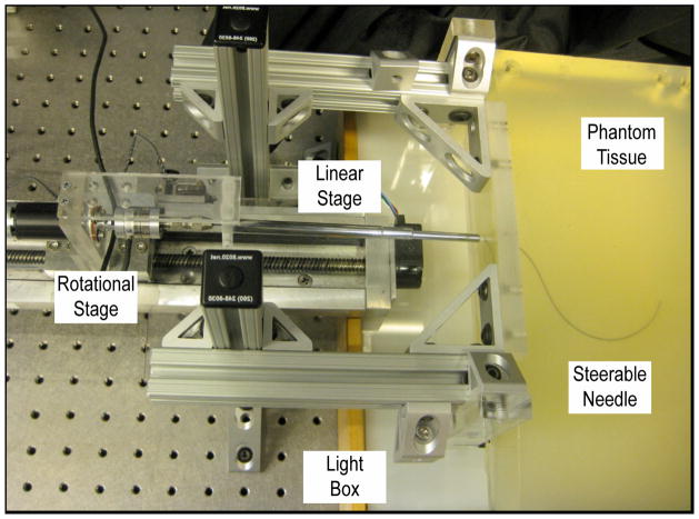
We performed multiple insertions of needles with various pre-curve arc lengths into phantom tissue. The needle tip and shaft were tracked during the insertions. This study used the Johns Hopkins University needle steering robot (Fig. 2) [14] and translucent Plastisol rubber (M-F Manufacturing Co., Fort Worth, TX) with a 4 to 1 ratio of regular stiffness plastic to plastic softener as a phantom tissue. This phantom tissue material was previously used in [12] and [13]. To remove the influence of tissue puncture effects and the tissue boundary, the needles were inserted into the tissue coaxially through a rigid copper tube with a 0.88mm I.D. that extended 2cm into the tissue. This copper tube simulated coaxial needle insertion through an introducer needle, which is common to many of the medical studies using curved needles [2][7][17]. Needles were inserted sufficiently far from previous needle tracts so that they did not influence the path of the needle. A third camera was also added to the robot to enable needle shaft reconstruction.
Fig. 2.
The Johns Hopkins needle steering robot inserting a needle into phantom tissue. The three cameras are not shown.
C. Needle Shaft Reconstruction
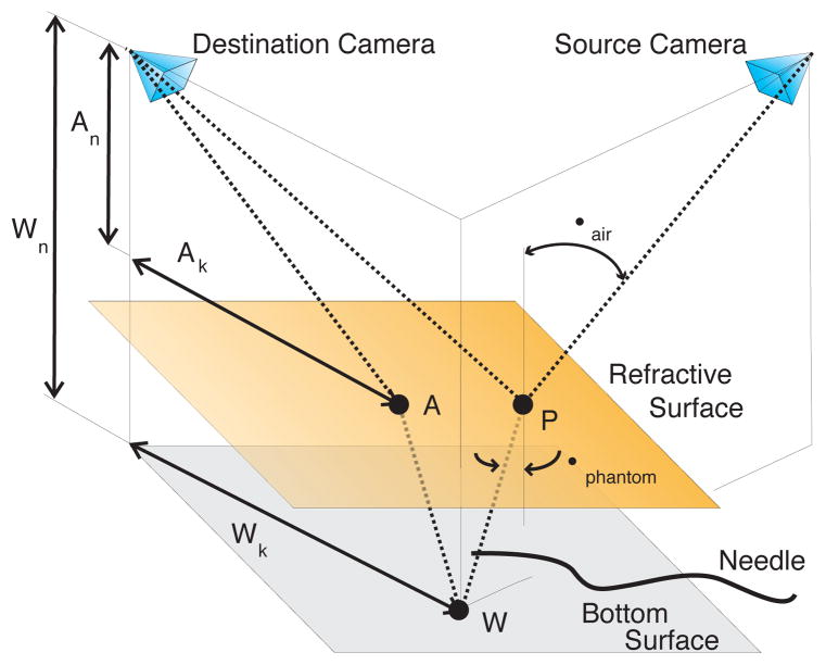
The three cameras were calibrated using the Multi-Camera Self-Calibration toolbox [19] and a fiber optic light pipe. The needles were segmented in the cameras’ images using a combination of background subtraction, smoothing to reduce noise, and thresholding. The needle centerlines were located using the method presented in [20]. Stereo geometry was used to reconstruct the shape of the needle. Using the needle centerline as source pixels, the corresponding refraction-corrected epipolar lines, which pair needle centerline pixels in the source camera to needle centerline pixels in the destination camera, were determined through the following algorithm (refer to Fig. 3 for variable definitions):
Fig. 3.
Transcendental geometry used to correct the epipolar lines for refraction in order to localize a steerable needle.
Select a needle centerline pixel in the source camera using image segmentation methods.
Project the selected pixel to a point P on the phantom tissue surface using the pinhole camera model. The projection of point P to the destination camera forms one endpoint of the refraction-corrected epipolar line.
-
Using Snell’s Law of Refraction,
(1) where ηair and ηphantom refer to the respective refractive index of the air and the phantom, determine the path the light ray takes within the phantom tissue; the needle lies along this path. Let the ray intersect the bottom surface of the phantom at point W. We assume ηair ≈ 1 and we determined ηphantom = 1.24.
-
Determine the path that light from point W takes to reach the destination camera. Let this path intersect the top tissue surface at point A. The geometry is described by the expression
(2) which has a closed-form solution; however, a numerical solution that recognizes logical geometric bounds is faster.
Project point A to the destination camera using the pinhole camera model; it will form the other endpoint of the refraction-corrected epipolar line.
The corrected epipolar lines pair a centerline pixel in one camera image to a line segment intersecting the needle in another camera image. Whenever the epipolar line is approximately orthogonal to the needle, the centroid of the overlapping portion of line segment is considered a pixel on the centerline of the needle. The third camera ensured that one could always select pairs of cameras such that there were epipolar lines approximately orthogonal to the entire needle shaft.
To find the needle tip in the images, we used a tracking algorithm that initiates at the needle base and then marches along the needle to the tip using a Hough Transform on a region of interest as a local approximation to the needle tangent.
D. Data Alignment
Comparing different needle insertions requires that the needle data reside in the same plane. To align data from different insertions, circles were iteratively fit to the needle data to determine the insertion plane. Every time a circle was fit to the data, the data was thresholded to remove outlying data points that were greater than two standard deviations away from the approximate circle. A circle was then fit to this new data. This iterative process repeated until circle convergence, thereby reducing the influence of outliers on the final circle. As will be discussed in the results section, a circle does not always accurately describe the shape of a pre-curved needle shaft. However, it can reasonably capture the needle’s plane and the path of the tip. Once the needle planes were determined, the needle data was rotated about the needle’s tissue insertion point so that all needle insertion data began at the origin.
III. Experimental Results And Discussion
A. Pre-Curve Arc Length Parameterizes Deflection
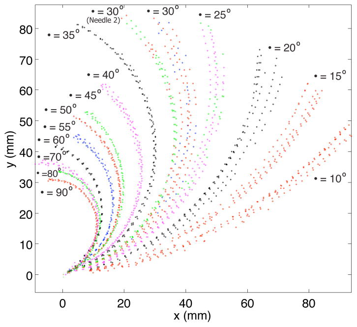
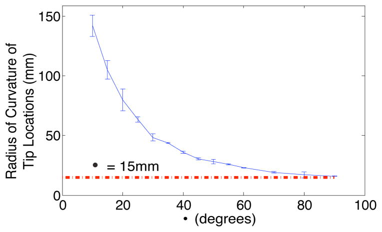
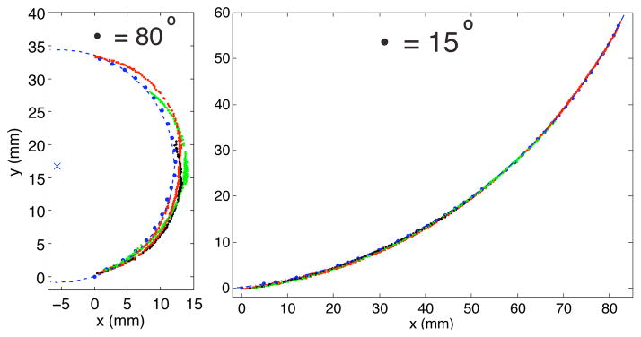
The path of the needle tip during insertions of needles with different pre-curve arc lengths is presented in Fig 4. Circles were iteratively fit to the tip locations to determine the radius of curvature of the tip path. Fig. 5 shows that the radius of curvature of the tip path was inversely proportional to the arc length of the pre-curve and approached the value of the radius of the pre-curvature for longer arc lengths of the pre-curve.
Fig. 4.
Positions of the needle tip recorded during multiple insertions. (Trajectories represent Needle 1 except where indicated, 1.5mm/s insertion speed)
Fig. 5.
As the arc length of the pre-curve increases, the radius of curvature of the path of the needle tip approaches the radius of the pre-curve. Vertical lines represent two standard deviations of the radius of curvature of the path of the tip. (This data is from Needle 1, 1.5mm/s insertion speed)
B. Comparing Pre-Curve and Bevel-Tip Needle Steering
The most suitable studies for comparison to these results are [13] and [12], which both present needle steering in equivalent phantom tissues. In [13], a 0.40mm diameter bevel-tipped nitinol needle was reported to have a 179.4mm radius of curvature, which is significantly larger than some of the radii presented in this paper. Reed et al. [12] presented the radius of curvature of a 0.61mm diameter nitinol needle with both a bevel and a pre-bend as 61mm, which is more representative of the radii of curvature observed in this study.
We also observed differences between how pre-curved and how bevel-tipped needles steer. A previous study [14] showed that the shaft of a bevel-tipped needle follows the path that the tip traveled through the tissue. This was observed for pre-curved needles with small to moderate arc length pre-curves, but the shaft of needles with long pre-curvature arc lengths deviated from the circular path taken by the needle tip during insertion (Fig 6). We hypothesize that this behavior is seen in any steerable needle with a small radius of curvature (relative to its bending stiffness) and a highly curved insertion path, and it is likely associated with larger stress and strain being placed on the tissue surrounding the needle.
Fig. 6.
The blue dashed circle centered about the blue × accurately describes the tip locations during the insertion (small blue dots) but it fails to represent the shape of the needle shaft at various insertion lengths (colored lines) when the pre-curve is long. (This data is from Needle 1, 1.5mm/s insertion speed)
C. Characteristics of Pre-Curved Needle Steering
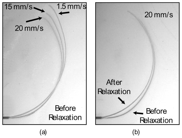
In performing this characterization, we observed a number of behaviors of pre-curved needle steering that are either seldom or never displayed by bevel-tipped needles. Path velocity dependence is one dynamic effect seen in pre-curved needles (Fig. 7) but not observed in bevel-tipped needles [14].
Fig. 7.
Two dynamic effects influence how pre-curved needles steer: insertion speed and relaxation. (a) Insertion speed affects the path that a needle cuts through the tissue during insertion. (b) Immediately after insertion, the needle and the tissue relax to a static equilibrium. A faster insertion speed correlates to more pronounced relaxation. (This data is from Needle 2, β = 30°.)
The extreme ability of a large arc length pre-curved needle to steer is uncontrollable. Needles with large pre-curve lengths (β > 40° for this experiment) could not be steadily rotated inside the tissue. When rotated, they stored torsional energy until they were eventually able to overcome the rotational resistance and snap to another angle. This is similar to the energy bifurcation of active cannulas discussed in [21]. Medium length pre-curvatures (β < 40° in this study) did not display energy bifurcations. However, they still displayed significant rotational resistance and, unlike bevel-tipped needles [22], simply retracting the needle a small amount did not enable the angle of the base of the needle to equal the angle of the tip. This poses a significant control issue for pre-curved needles and points to the need for strategies to simultaneously insert and rotate them.
We also observed that pre-curved needles possess the dexterity to plastically strain themselves. As previously stated, two needles were constructed with the same geometry. After 75 insertions with Needle 1, it was observed that the needle was no longer in its fabricated shape. The pre-curved section was still in its constructed shape, but the straight portion of the needle near the start of the pre-curve had a slight taper. We initially hypothesized that the taper would enhance the effect of the pre-curve and result in a smaller radius of curvature. As Fig. 4 shows, however, Needle 2 displayed a smaller radius of curvature than the first needle, which emphasizes the importance of further characterizing pre-curved needles to enable effective path planning and control strategies.
IV. Conclusions And Future Work
We conducted an experimental characterization of pre-curved needles that confirmed their potential to be highly steerable, but also illustrated some of the control issues that must be addressed before they will become clinically feasible. This work serves as a first step towards developing a model and control strategies for steering pre-curved needles in biological tissue under medical imager feedback. Since the shaft of a pre-curved needle deviates from the path of the tip, potential tissue damage caused by pre-curved needles will also have to be addressed.
Acknowledgments
This work was supported by NIH grant R01 EB006435, a DHS fellowship and a NDSEG fellowship.
The authors acknowledge Noah Cowan, Kyle Reed, and John Swensen.
References
- 1.Kopacz DJ, et al. Comparison of needle deviation during regional anesthetic techniques in a laboratory model. Anesth Analg. 1995;81(3):630–633. doi: 10.1097/00000539-199509000-00037. [DOI] [PubMed] [Google Scholar]
- 2.Sitzman BT, et al. The effects of needle type, gauge, and tip bend on spinal needle deflection. Anesth Analg. 1996;82(2):297–301. doi: 10.1097/00000539-199602000-00014. [DOI] [PubMed] [Google Scholar]
- 3.Ahn WS, et al. The effect of introducer gauge, design and bevel direction on the deflection of spinal needles. Anaesthesia. 2002;57(10):1007–1011. doi: 10.1046/j.1365-2044.2002.02657.x. [DOI] [PubMed] [Google Scholar]
- 4.Okamura AM, et al. Force modeling for needle insertion into soft tissue. IEEE Transactions on Biomedical Engineering. 2004;51(10):1707–1716. doi: 10.1109/TBME.2004.831542. [DOI] [PubMed] [Google Scholar]
- 5.Misra S, et al. Needle-tissue interaction forces for bevel-tip steerable needles. IEEE International Conference on Biomedical Robotics and Biomechatronics; 2008. pp. 224–231. [DOI] [PMC free article] [PubMed] [Google Scholar]
- 6.Barb L, et al. Needle insertions modeling: Identifiability and limitations. Biomedical Signal Processing and Control. 2007;2(3):191–198. [Google Scholar]
- 7.Singh AK, et al. Core biopsy with curved needle technique. AJR Am J Roentgenol. 2008;191(6):1745–1750. doi: 10.2214/AJR.08.1165. [DOI] [PubMed] [Google Scholar]
- 8.Webster RJ, III, et al. Nonholonomic modeling of needle steering. International Journal of Robotics Research. 2006 May/June;25(5/6):509–526. [Google Scholar]
- 9.Okazawa S, et al. Hand-held steerable needle device. IEEE/ASME Transactions on Mechatronics. 2005;10(3):285–296. [Google Scholar]
- 10.DiMaio SP, et al. Needle steering and model-based trajectory planning. Medical Image Computing and Computer-Assisted Intervention. 2003:33–40. [Google Scholar]
- 11.Glozman D, et al. Image-guided robotic flexible needle steering. IEEE Trans on Rob. 2007;23(3):459–467. [Google Scholar]
- 12.Reed KB, et al. Integrated planning and image-guided control for planar needle steering. IEEE International Conference on Biomedical Robotics and Biomechatronics; 2008. pp. 819–824. [DOI] [PMC free article] [PubMed] [Google Scholar]
- 13.Misra S, et al. Observations and models for needle-tissue interactions. IEEE International Conference on Robotics and Automation; 2009. in Press. [DOI] [PMC free article] [PubMed] [Google Scholar]
- 14.Webster RJ, III, et al. Design considerations for robotic needle steering. IEEE International Conference on Robotics and Automation; 2005. pp. 3599–3605. [Google Scholar]
- 15.Sze DY. Use of curved needles to perform biopsies and drainages of inaccessible targets. J Vasc Interv Radiol. 2001;12(12):1441–1444. doi: 10.1016/s1051-0443(07)61706-0. [DOI] [PubMed] [Google Scholar]
- 16.Gupta S, et al. Using a coaxial technique with a curved inner needle for ct-guided fine-needle aspiration biopsy. AJR Am J Roentgenol. 2002;179(1):109–112. doi: 10.2214/ajr.179.1.1790109. [DOI] [PubMed] [Google Scholar]
- 17.Levy WJ, et al. Curved biopsy needle for stereotactic surgery: a technical note. Neurosurgery. 1984;15(1):82–85. doi: 10.1227/00006123-198407000-00015. [DOI] [PubMed] [Google Scholar]
- 18.Warnock NG. Curved needle technique for the avoidance of interposed structures in CT-guided percutaneous fine needle biopsy. J Comput Assist Tomogr. 1996;20(5):826–828. doi: 10.1097/00004728-199609000-00031. [DOI] [PubMed] [Google Scholar]
- 19.Svoboda T, et al. A convenient multicamera self-calibration for virtual environments. Presence: Teleoperators and Virtual Environments. 2005;14(4):407–422. [Google Scholar]
- 20.Steger C. Extracting curvilinear structures: A differential geometric approach. Fourth European Conference on Computer Vision; Springer-Verlag. 1996. pp. 630–641. [Google Scholar]
- 21.Webster RJ., III . PhD Thesis, Dept Mech Eng. The Johns Hopkins Univ; 2007. Design and mechanics of continuum robotics for surgery. [Google Scholar]
- 22.Reed KB, et al. Controlling a robotically steered needle in the presence of torsional friction. IEEE International Conference on Robotics and Automation; 2009. in Press. [DOI] [PMC free article] [PubMed] [Google Scholar]


