Abstract
The purpose of this article is to present a wide field electrode array that may increase the field of vision in patients implanted with a retinal prosthesis.
Mobility is often impaired in patients with low vision, particularly in those with peripheral visual loss. Studies on low vision patients as well as simulation studies on normally sighted individuals have indicated a strong correlation between the visual field and mobility. In addition, it has been shown that increased visual field is associated with a significant improvement in visual acuity and object discrimination. Current electrode arrays implanted in animals or human vary in size; however, the retinal area covered by the electrodes has a maximum projected visual field of about 10°. We have designed wide field electrode arrays that could potentially provide a visual field of 34°, which may significantly improve the mobility. Tests performed on a mechanical eye model showed that it was possible to fix flexible polyimide dummy electrode arrays of 10 mm wide onto the retina using a single retinal tack. They also showed that the arrays could conform to the inner curvature of the eye. Surgeries on an enucleated porcine eye model demonstrated feasibility of implantation of 10 mm wide arrays through a 5 mm eye wall incision.
Keywords: Wide field, electrode array, retinal prosthesis, visual field, mobility, retinitis pigmentosa, age related macular degeneration
1. Introduction
Retinal prostheses are being developed to apply electrical stimulation to the retina in order to restore vision in patients with degenerative outer retinal disease such as Retinitis Pigmentosa (RP) and Age Related Macular Degeneration (AMD). In these conditions, there is a significant loss of photoreceptor cells in the outer retina, but in the inner retinal layers a certain percentage of cells remain viable [1, 2]. Despite evidence of retinal remodeling in retinal degenerative disease [3], it has been shown that electrical retinal stimulation can result in visual perception in patients with profound visual loss [4, 5]. Moreover, chronic implantation of a 16 channel retinal prosthesis has resulted in improved visual performance in patients with severe visual impairment [6].
For a retinal prosthesis to be successful, it should properly address the visual needs of patients with outer retinal disease. While both patients with advanced AMD and RP suffer from central visual loss, those with RP have impairment of peripheral vision as well. In addition to having difficulty with reading and writing, both groups of patients have mobility problem. The purpose of this article is to present a wide field electrode array that may improve mobility performance, and perhaps visual acuity, in patients with outer retinal disease, and in particular, RP.
2.1. Mobility in AMD and RP
Mobility is a process involving navigation and orientation; it enables one to correctly recognize one's position with respect to the immediate environment and move safely from one location to another [7, 8]. As the mobility performance declines the walking speed decreases and one repeatedly bumps into objects. For a visually impaired person, maintaining mobility may be as important as the ability to read and write.
Although AMD spares peripheral vision, the mobility performance of AMD patients is affected by the disease and is inversely related to the size of their binocular central scotoma [9]. The reduction in mobility performance is most pronounced in low light conditions [10].
Mobility is even a bigger problem in RP patients. Depending on the type of inheritance of RP, the age at which clinical manifestations appear significantly varies. Nevertheless, in early stages of the disease, in majority of cases night blindness is the hallmark of the disease followed by gradual visual field loss. Central vision is often preserved until the final stages of the disease. It is understandable that at the end stage disease, when patients loose both peripheral and central visions, the mobility would be impaired. However, mobility performance declines in majority of patients long before the end stage disease. In one study, about 80 % of patients at various stages of the disease reportedly had mobility problem [11].
2.2. Mobility and Visual Field
Using questionnaires and functional tasks, numerous studies have evaluated mobility performance in low vision patients in the past four decades. Difficulty with mobility has been reported in a variety of ocular diseases including AMD, RP and glaucoma. Visual field, contrast sensitivity and visual acuity have all been implicated in mobility. While there are conflicting reports on the role of visual acuity [7, 12, 13] and, to a less extent, contrast sensitivity[13, 14] in mobility, almost all studies have shown a significant correlation between the visual field and mobility performance in low vision patients [7, 9-13, 15-18]. As the visual field decreases the mobility performance declines. In fact, because of severe mobility impairment associated with constricted visual field, individuals with visual field of 20° or less are regarded as legally blind in the US, regardless of their visual acuity level.
The effect of narrow visual field on mobility has been known to clinicians and vision scientists for a long time, and several investigators have tried to expand the remaining visual field in RP and glaucoma patients by means of optical devices [19, 20]. Hoeft et al reported immediate improvement in mobility in one-half of RP patients who used amorphic lenses for visual field expansion [21].
2.3. Mobility and Simulation Studies
Cha et al was the first to study the requirements for mobility under pixelized vision conditions [22]. Psychophysical experiments were conducted on normally sighted human subjects who were required to walk through a maze, which included a series of obstacles, while their visual input was restricted to information from a pixelized vision simulator. Walking speed and number of body contacts with obstacles and walls were used to evaluate the effects of pixel number, pixel spacing, object minification, and field of view on mobility. Minification is the opposite of magnification and refers to decrease in the image size. The study found that visual field and number of pixels had higher correlations with performance than pixel spacing or object minification factor and that the best single variable correlation with walking speed was the visual field. The study also indicated that a 25 × 25 pixel array with 30° of visual field could provide adequate mobility skills including good obstacle avoidance and a sense of confidence to patients in familiar environments, and a walking speed comparable to normal individuals.
In another study on normal individuals, Dagneli et al used real and virtual mobility tests to compare the effects of 4 × 4, 6 × 10, and 16 × 16 simulated pixel arrays on mobility performance [23]. The study found that a 16 × 16 grid resolution simulator image, covering 27° × 27° of visual field, could provide adequate mobility even for inexperienced individuals. It also indicated that a less dense, 6 × 10 grid resolution electrode array, covering 27° × 16° of visual field, may provide independent way finding abilities but only after substantial practice and supervision.
3.1. Retinal Prosthesis and visual field
Almost all retinal prostheses are composed of a video camera for capturing image data, an implanted microelectronic for converting image data into a stimulus pattern, and an electrode array interface for delivering the stimulus current to the retina.
The visual field is directly related to the size of stimulated area of the retina and hence the diameter of the electrode array. The projected visual field for every 1 mm of the retina is about 3.35°[24]. Current electrode arrays implanted in animals or human (regardless of whether they are dummy or functional) range from 3 × 3 mm to 5.5 × 6 mm in size [6, 25-35]. Since the most peripheral parts of the array do not contain electrodes, the retinal area covered by electrodes is usually significantly smaller. For instance, the retinal area covered by the largest implanted electrode array in human (5.5 × 6 mm) is less than 3 × 3 mm. This would provide a central vision with a field of view of about 10° × 10°. Assuming future advances in engineering will allow fabrication of a highly dense electrode array that can be placed in close proximity of the retina and can provide a 20/20 vision, using a current size electrode arrays may, at best, functionally turn a RP patient to an advanced glaucoma patient. This patient would still have significant difficulty with mobility and would be regarded as legally blind in the US.
To improve the visual field in patients implanted with a retinal prosthesis two approaches may be taken.
1) Capturing a wide field image and presenting it to a small area of the retina through current size electrode arrays. This is relatively similar to using optical visual field expanders in patients with preserved central vision. The problem with this approach is that the visual field is increased at the expense image size and visual acuity, as such a system would inherently be associated with minification of the perceived image. There is also a limit as to how much the mobility could be improved with this approach. Cha et al who used a similar system for increasing the visual field in their simulation studies, noted a decline in mobility performance beyond 30° of visual field [22]. Although they attributed this to image minification, it is plausible that other factors may have also played a role. When a wide field is presented to a small area of the retina, a crowding phenomenon occurs in which the objects appear to be closer to each other. This crowding is a result of image displacement. However, the image displacement is not equal for all objects. While objects right in front of the video camera may not be displaced, the objects at far periphery may be displaced by several meters. The unequal image displacement could seriously compromise the ability of the patient in properly locating the visible objects.
Simulation studies, in general, have shown a significant improvement in visual performance with practice [23, 36, 37]. It is possible that patients implanted with this type of prosthesis adapt to image minification and crowding. However, the adaptation limit and the ultimate mobility performance would depend on the ratio of the field of view of the video camera to the projected visual field covered by the area of the retina underneath the array. The same ratio could also determine the level of visual acuity. Moreover, since adaptation involves an active learning process, inherent learning ability of each individual could also determine one's adaptation limit.
2) Using a wide field electrode array. Increasing the size of the electrode array proportional to the field of view captured by the video camera would prevent image minification and crowding. Moreover, the benefits of using a wide filed array may be more than just improving the mobility. Simulation studies on normal individuals carried out by Hayes et al indicated a significant improvement in visual acuity related tasks with a 6 × 10 array translating into 11.3 ° × 19.3 ° of visual field compared to a 4 × 4 array of the same density covering 7.3° × 7.3° of visual field [37]. They found the array size to be the only parameter of significant effect in object discrimination tests, in which subjects had to identify various objects such as a cup, plate, fork, etc.
Figure 1 shows the effect of the electrode array size in increasing the visual field. As it is evident in the figure, increasing the diameter of the electrode array dramatically increases the visual field. In addition, during head scanning a wide electrode array provides a greater spatial and temporal integration. This is of particular importance in patients with retinal prosthesis who have been shown to perform better with head scanning [6].
Figure 1.

Comparison of the projected visual field of a 5 mm electrode array (orange circle) with a 10 mm electrode array (yellow circle) within the normal monocular horizontal visual field (from -60°to 90°). When the eye moves from point A to point B, there is a significant overlapping of the visual field in a patient with a 10 mm array compared to no overlapping in a patient with a 5 mm array. This overlapping allows a greater spatial and temporal integration of the image.
Furthermore, the electrical interference between the neighboring electrodes depends on the distance between the electrodes themselves and the distance between the electrodes and the target cells in the retina [38]. One of the advantages of using a wide field electrode array is its bigger surface area, which may reduce the need for having a very dense electrode array, and therefore could decrease cross-talk between the neighboring electrodes. For example, the surface area of a 10 mm wide array is four times bigger than that of a 5 mm array and as a result it can accommodate four times more electrodes of the same density. In a wide field array, while the electrode density could be kept low to prevent electrical interference, it is possible to produce images of higher resolution and magnification from objects of interest by using a camera with a zooming capability. If a small field of view captured by the camera is presented to a large area of the retina, the perceived image would be expected to have both a higher resolution and magnification. This feature may be used for reading street signs, visualizing objects in more detail, or even reading and writing. The practical usefulness of such a system, however, would depend on the adaptation ability of the visual pathways and cortex, and remains to be determined.
Morphometric analysis of the retina in RP patients has shown a less preservation of the ganglion cells in the extrmacular region compared to the macula [39]. In addition, it has been shown that the extramacular region in RP patients requires a higher current threshold for electrical stimulation compared to the macula [40]. These observations may indicate that in a wide field electrode array the peripheral electrodes may have to be of a less density and/or bigger size to achieve electrical stimulation.
3.2. Wide field electrode array
We have designed a 10 mm wide electrode array, which could provide 34° of visual field. Based on clinical observations, it has been stated that if a patient maintains 40° of visual field his/her orientation-mobility would not be greatly impaired [7, 41]. Simulation studies have indicated that even a visual field of about 30° may provide a near normal mobility [22, 23].
Increasing the size of the electrode array is associated with two main challenges: it requires a large scleral incision, and the array may not conform to the curvature of the eye. If a flat electrode array is placed over the retina, due to the curvature of the eye the central electrodes will not have the same proximity to the retina as the peripheral electrodes. The distance between the central electrodes and the retina is related to the size of the electrode array and the curvature of the eye (fig. 2). For example, for a 5 mm array in an eye with 12 mm radius of curvature, this distance would be about 260 μm, whereas for a 10 mm wide array it could increase to about 1010 μm. Such a far distance would inevitably increase the stimulation threshold and the interference between the adjacent electrodes.
Figure 2.
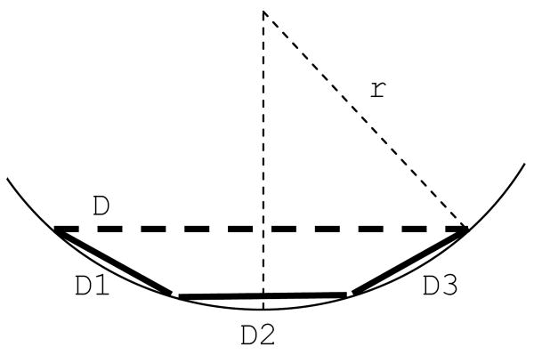
The distance between the central electrodes and the retina (x) depends on the diameter of the electrode array (D) and the radius of curvature of the eye (r)
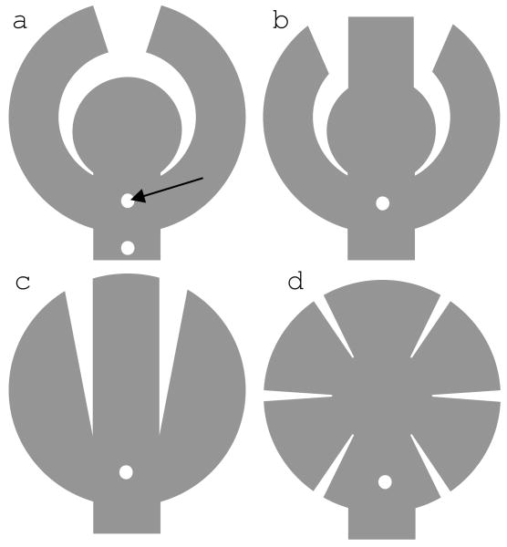
On the other hand, brining the center of the electrode array closer to the retina by simply pushing on the center of the array would cause wrinkling of the peripheral parts of the array. This would subsequently result in unequal distance between the retina and the adjacent peripheral electrodes and could result in mechanical retinal damage. To address this problem, we have designed various electrode arrays in which the array is divided in several smaller parts to allow the array to conform to the curvature of the eye (fig. 3 and 4). These designs also allow implantation of the array through a small scleral incision by overlapping the parts on each other.
Figure 3.
Dividing the electrode array (D) into smaller parts (D1, D2 and D3) reduces the distance between the central electrodes and the retina.
Figure 4.
Wide field arrays of various shapes. Small holes in each array (arrow) are used for tacking. Array a (concentric array) has two holes: one between the arms and another in the cable.
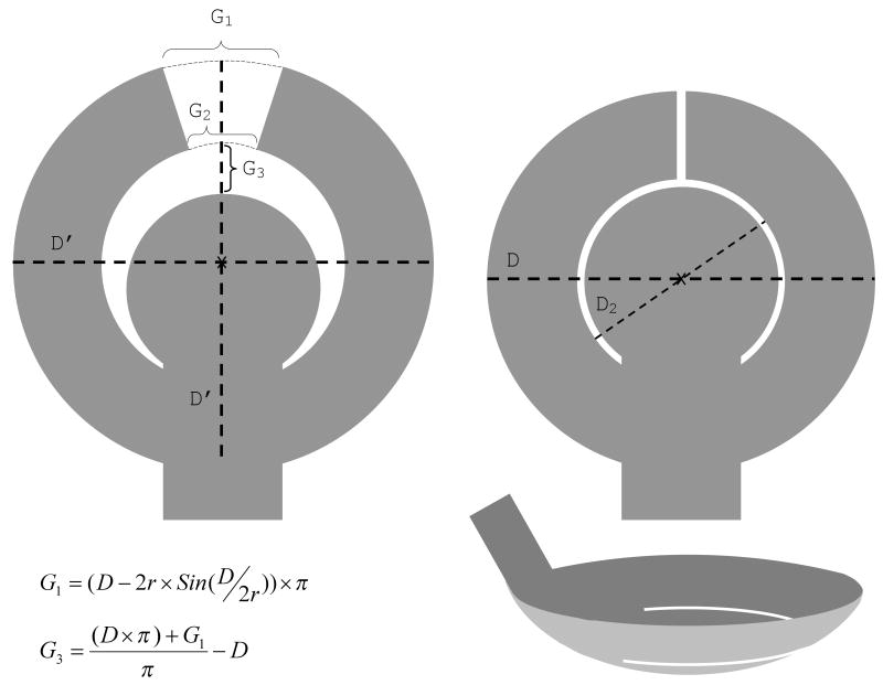
For example, in a so-called concentric design the electrode array is composed of a central part and two peripheral arms (fig. 4a and 5). The gaps between the two arms and between the arms and the central part allow the array to conform to the curvature of the eye without wrinkling. The other arrays also follow the same principle.
Figure 5.
Concentric array design. Left: A flat array before implantation shows gaps between the two arms and the arms and the central part. Right: following the implantation the arms move towards each other and the central part to close the gaps and the array conforms to the curvature of the eye. The gaps can be calculated using the above equations. The equation for G2 is the same as that of G1, except that D2 replaces D. The desired final gap after tacking can be added to the calculations. D′ is the diameter of the electrode array before conformation, and equals D plus G3. D and D2 are the diameters of the electrode array and the inner circle following conformation, respectively. r: radius of curvature of the eye.
3.2.1. Mechanical Testing
A mechanical eye model, made of acrylic material, was used to compare wide field arrays of various shapes (fig. 4). The inner cavity and the anterior and posterior surfaces of the model matched the shape of the human eye, including the steeper curvature of the cornea. Small holes, filled with silicone, were incorporated in the posterior part for tacking the array. The arrays were fixed to the interior surface using retinal tacks, and the cavity was filled with fluid before evaluating the arrays with Optical Coherence Tomography (OCT). OCT is a technology that provides cross sectional images of living tissues, comparable to histopathological images. In ophthalmology, it is mainly used to study the structure of the retina. OCT is very useful in measuring the distance between the retina and the electrode array.
All the arrays were made of a thin film of polyimide and were very flexible. Overall, a single tack was enough to hold a 10 mm wide field array close to the inner surface of the mechanical eye model. All the arrays were able to conform to the curvature of the eye, and the maximum distance between the center of the electrode array and the inner surface was less than 250μm. To evaluate the effect of the location of the tack hole on the conformity of the array to the inner curvature of the eye, two different positions were used for tacking the concentric array (fig. 5A). It was noted that when the tack was placed between the arms the array conformed better to the inner curvature of the eye than when it was placed along the cable. As an example, figure 6 shows representative OCT images of a concentric array implanted in a mechanical eye model. The pattern of conformation was similar to the diagram shown in figure 3, with the exception that the inner edge of the arms did not contact the inner surface of the mechanical eye model in the midsection of the array (fig. 6C). In addition, the arms slightly overlapped at the tip; this was due to having a smaller gap between the arms because of a miscalculation.
Figure 6.
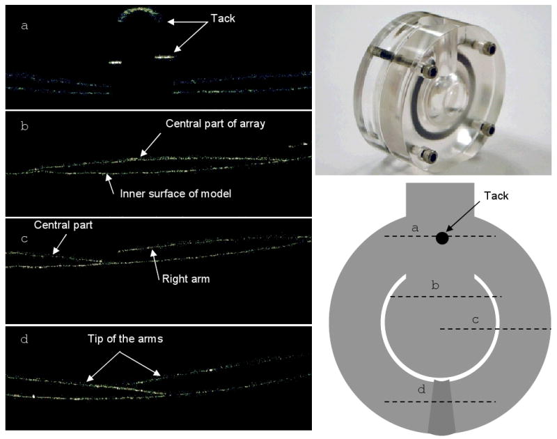
Representative radial line OCT images (left) of a concentric array (bottom right) implanted in a mechanical eye model (top right). The cross section of each line is displayed on the concentric array; the direction of each line is from left to right. In this array, the gap between the arms was not sufficient and as a result there was overlapping of the tip of the arms (d)
3.2.2. Implantation of the arrays in enucleated porcine eye
Arrays a (concentric), b and c in figure 4 are similar in shape, and were comparable in conforming to the curvature of the mechanical eye model. However, arrays b and c have more sharp corners and are more likely to cause retinal damage. For this reason, the “concentric” (fig. 4a) and “radial cut” (fig. 4d) designs were used to test the feasibility of implanting a 10 mm wide array through a 5 mm incision in the eye wall. Although there has been no study to evaluate the effect of the size of scleral incision on surgical complications, there are overwhelming evidence that in perforated eye injuries, bigger size intraocular foreign bodies and larger scleral wounds are associated with worse visual prognosis [42-46]. Current electrode arrays are inserted through a 5 mm scleral incision. It is thought that larger incisions may increase the risk of surgical complications such as retinal detachment and intraocular hemorrhage, and should be avoided if possible.
It was possible to implant both designs through a 5 mm scleral incision. For the radial cut design, a polyimide tube was used to roll the array. Implantation of the concentric array was significantly easier (fig. 7). By overlapping the arms on the central part, it was possible to easily insert the array into the eye using a forceps. When the array is dry, it tends to flatten immediately after the forceps is removed, but if it is wet, the arms remain overlapped (fig. 7A). Since the array is flexible, the surface tension of the fluid is enough to keep the arms overlapped; however, once the array is inside the vitreous cavity and the forceps is removed, the array automatically unfolds. Interestingly, if for any reason it is necessary to remove the array, it can be done by simply pulling the cable out; the arms automatically overlap and the array exits the eye through a 5 mm scleral incision without any damage.
Figure 7.
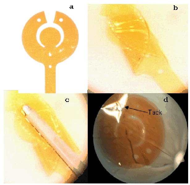
Implantation of a concentric array (a) in an enucleated porcine eye. b, the arms are overlapped on the central part; c, the overlapped arms are grabbed with a forceps for implantation; d; the implanted array is fixed onto the retina with a tack (the light reflection has obscured the tack image). The two holes at the tip of the peripheral arms are for surgical manipulation purposes.
3.3. Future Direction
The significance of visual field on mobility and visual acuity has been demonstrated in previous studies on low vision patients. Simulation studies on subjects with normal vision have also reached the same conclusion. Current electrode arrays, implanted in animal or human, provide a limited visual field and are unlikely to be of significant help in providing mobility. Increasing the size of the electrode array appears to be the best option in order to increase the visual field in patients implanted with a retinal prosthesis. However, implantation of a large electrode array brings on new challenges. Most importantly, as the size of the electrode array increases, the conformity of the array to the curvature of the eye becomes more imperative. We have designed wide field electrode arrays, which can conform to the curvature of the eye and can be implanted through a small scleral incision.
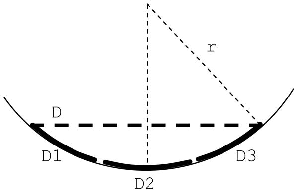
For a wide field electrode array, to conform to the curvature of the eye it requires to be very flexible. However, even then, in each section of the array the central electrodes may not be very close to the retina (fig. 3, 6B). For example, if a 10 mm wide electrode array with a 4 mm wide central part and 3 mm wide arms is implanted in an average eye with a radius of curvature of 12 mm, the electrodes in the middle of the central part and the arms will have a distance of about 170 μm and 90 μm from the retina, respectively. One potential solution to tackle this problem could be pre-curving the electrode arrays during the fabrication (fig. 8). Nevertheless, one should keep in mind that the curvature of the eye varies among individuals and a fixed curvature may not fit every individual eye. Ideally, the curvature of the array should be customized to the curvature of each individual eye.
Figure 8.
A pre-curved wide field electrode array. If the curvature of the array matches the curvature of the eye, all sections of the electrode array could be in contact or very close to the retina. D: a flat array; D1, D2, and D3: sections of a pre-curved wide field array
The concentric array design allows fabrication of even larger electrode arrays by adding more arms to each side of the array. However, as the size of the array increases new challenges arise. For example, flexibility of the array may become more important, the implantation may become more difficult, more than one tack may be needed for fixing the array onto the retina, the cable passing through the eye wall may become too wide or too thick, and finally the risk of surgical complications and mechanical damage may increase. At present, a 10 mm wide field array is a significant step forward. Future in vivo studies will illustrate how practical this approach is, and what the prospect of larger electrode arrays would be.
Acknowledgments
This work was supported by NIH R44 NS041113
Footnotes
Financial disclosure: All authors: patent pending
Mark S. Humayun: Second Sight Medical Products
Stefan Ufer ad Helmut Eckhardt: Premitec Inc.
Publisher's Disclaimer: This is an author-created, un-copyedited version of an article accepted for publication in “Journal of Neural Engineering”. IOP Publishing ltd is not responsible for any errors or omissions in this version of the manuscript or any version derived from it. The definitive publisher authenticated version is available on-line at doi: 10.1088/1741-2560/6/3/035002
References
- 1.Kim SY, et al. Morphometric analysis of the macula in eyes with geographic atrophy due to age-related macular degeneration. Retina. 2002;22(4):464–70. doi: 10.1097/00006982-200208000-00011. [DOI] [PubMed] [Google Scholar]
- 2.Santos A, et al. Preservation of the inner retina in retinitis pigmentosa. A morphometric analysis. Arch Ophthalmol. 1997;115(4):511–5. doi: 10.1001/archopht.1997.01100150513011. [DOI] [PubMed] [Google Scholar]
- 3.Marc RE, Jones BW. Retinal remodeling in inherited photoreceptor degenerations. Mol Neurobiol. 2003;28(2):139–47. doi: 10.1385/MN:28:2:139. [DOI] [PubMed] [Google Scholar]
- 4.Humayun MS, et al. Visual perception elicited by electrical stimulation of retina in blind humans. Arch Ophthalmol. 1996;114(1):40–6. doi: 10.1001/archopht.1996.01100130038006. [DOI] [PubMed] [Google Scholar]
- 5.Rizzo JF, 3rd, et al. Perceptual efficacy of electrical stimulation of human retina with a microelectrode array during short-term surgical trials. Invest Ophthalmol Vis Sci. 2003;44(12):5362–9. doi: 10.1167/iovs.02-0817. [DOI] [PubMed] [Google Scholar]
- 6.Yanai D, et al. Visual performance using a retinal prosthesis in three subjects with retinitis pigmentosa. Am J Ophthalmol. 2007;143(5):820–827. doi: 10.1016/j.ajo.2007.01.027. [DOI] [PubMed] [Google Scholar]
- 7.Marron JA, I, Bailey L. Visual factors and orientation-mobility performance. Am J Optom Physiol Opt. 1982;59(5):413–26. doi: 10.1097/00006324-198205000-00009. [DOI] [PubMed] [Google Scholar]
- 8.Jones T, Troscianko T. Mobility performance of low-vision adults using an electronic mobility aid. Clin Exp Optom. 2006;89(1):10–7. doi: 10.1111/j.1444-0938.2006.00004.x. [DOI] [PubMed] [Google Scholar]
- 9.Hassan SE, Lovie-Kitchin JE, Woods RL. Vision and mobility performance of subjects with age-related macular degeneration. Optom Vis Sci. 2002;79(11):697–707. doi: 10.1097/00006324-200211000-00007. [DOI] [PubMed] [Google Scholar]
- 10.Brown B, et al. Contribution of vision variables to mobility in age-related maculopathy patients. Am J Optom Physiol Opt. 1986;63(9):733–9. doi: 10.1097/00006324-198609000-00006. [DOI] [PubMed] [Google Scholar]
- 11.Geruschat DR, Turano KA, Stahl JW. Traditional measures of mobility performance and retinitis pigmentosa. Optom Vis Sci. 1998;75(7):525–37. doi: 10.1097/00006324-199807000-00022. [DOI] [PubMed] [Google Scholar]
- 12.Szlyk JP, et al. Relationship between difficulty in performing daily activities and clinical measures of visual function in patients with retinitis pigmentosa. Arch Ophthalmol. 1997;115(1):53–9. doi: 10.1001/archopht.1997.01100150055009. [DOI] [PubMed] [Google Scholar]
- 13.Turano KA, Rubin GS, Quigley HA. Mobility performance in glaucoma. Invest Ophthalmol Vis Sci. 1999;40(12):2803–9. [PubMed] [Google Scholar]
- 14.Friedman DS, et al. Glaucoma and mobility performance: the Salisbury Eye Evaluation Project. Ophthalmology. 2007;114(12):2232–7. doi: 10.1016/j.ophtha.2007.02.001. [DOI] [PubMed] [Google Scholar]
- 15.Haymes S, et al. Mobility of people with retinitis pigmentosa as a function of vision and psychological variables. Optom Vis Sci. 1996;73(10):621–37. doi: 10.1097/00006324-199610000-00001. [DOI] [PubMed] [Google Scholar]
- 16.Szlyk JP, et al. Perceived and actual performance of daily tasks: relationship to visual function tests in individuals with retinitis pigmentosa. Ophthalmology. 2001;108(1):65–75. doi: 10.1016/s0161-6420(00)00413-9. [DOI] [PubMed] [Google Scholar]
- 17.Turano KA, et al. Association of visual field loss and mobility performance in older adults: Salisbury Eye Evaluation Study. Optom Vis Sci. 2004;81(5):298–307. doi: 10.1097/01.opx.0000134903.13651.8e. [DOI] [PubMed] [Google Scholar]
- 18.Burstedt MS, Monestam E, Sandgren O. Associations between specific measures of vision and vision-related quality of life in patients with bothnia dystrophy, a defined type of retinitis pigmentosa. Retina. 2005;25(3):317–23. doi: 10.1097/00006982-200504000-00011. [DOI] [PubMed] [Google Scholar]
- 19.Holm OC. A simple method for widening restricted visual fields. Arch Ophthalmol. 1970;84(5):611–2. doi: 10.1001/archopht.1970.00990040613010. [DOI] [PubMed] [Google Scholar]
- 20.Kozlowski JM, Mainster MA, Avila MP. Negative-lens field expander for patients with concentric field constriction. Arch Ophthalmol. 1984;102(8):1182–4. doi: 10.1001/archopht.1984.01040030960025. [DOI] [PubMed] [Google Scholar]
- 21.Hoeft WW, et al. Amorphic lenses: a mobility aid for patients with retinitis pigmentosa. Am J Optom Physiol Opt. 1985;62(2):142–8. [PubMed] [Google Scholar]
- 22.Cha K, Horch KW, Normann RA. Mobility performance with a pixelized vision system. Vision Res. 1992;32(7):1367–72. doi: 10.1016/0042-6989(92)90229-c. [DOI] [PubMed] [Google Scholar]
- 23.Dagnelie G, et al. Real and virtual mobility performance in simulated prosthetic vision. J Neural Eng. 2007;4(1):S92–101. doi: 10.1088/1741-2560/4/1/S11. [DOI] [PubMed] [Google Scholar]
- 24.Tychsen L. In: Binocular Vision, in Adler's Physiology of The Eye. Hart WM, editor. Mosby Year Book; St. Louis: 1992. pp. 773–853. [Google Scholar]
- 25.Majji AB, et al. Long-term histological and electrophysiological results of an inactive epiretinal electrode array implantation in dogs. Invest Ophthalmol Vis Sci. 1999;40(9):2073–81. [PubMed] [Google Scholar]
- 26.Peyman G, et al. Subretinal semiconductor microphotodiode array. Ophthalmic Surg Lasers. 1998;29(3):234–41. [PubMed] [Google Scholar]
- 27.Kerdraon YA, et al. Development and surgical implantation of a vision prosthesis model into the ovine eye. Clin Experiment Ophthalmol. 2002;30(1):36–40. doi: 10.1046/j.1442-9071.2002.00485.x. [DOI] [PubMed] [Google Scholar]
- 28.Mahadevappa M, et al. Perceptual thresholds and electrode impedance in three retinal prosthesis subjects. IEEE Trans Neural Syst Rehabil Eng. 2005;13(2):201–6. doi: 10.1109/TNSRE.2005.848687. [DOI] [PubMed] [Google Scholar]
- 29.Terasawa Y, et al. The development of a multichannel electrode array for retinal prostheses. J Artif Organs. 2006;9(4):263–6. doi: 10.1007/s10047-006-0352-1. [DOI] [PubMed] [Google Scholar]
- 30.Johnson L, et al. Impedance-based retinal contact imaging as an aid for the placement of high resolution epiretinal prostheses. J Neural Eng. 2007;4(1):S17–23. doi: 10.1088/1741-2560/4/1/S03. [DOI] [PubMed] [Google Scholar]
- 31.Gerding H, Benner FP, Taneri S. Experimental implantation of epiretinal retina implants (EPI-RET) with an IOL-type receiver unit. J Neural Eng. 2007;4(1):S38–49. doi: 10.1088/1741-2560/4/1/S06. [DOI] [PubMed] [Google Scholar]
- 32.Loudin JD, et al. Optoelectronic retinal prosthesis: system design and performance. J Neural Eng. 2007;4(1):S72–84. doi: 10.1088/1741-2560/4/1/S09. [DOI] [PubMed] [Google Scholar]
- 33.Schanze T, et al. An optically powered single-channel stimulation implant as test system for chronic biocompatibility and biostability of miniaturized retinal vision prostheses. IEEE Trans Biomed Eng. 2007;54(6 Pt 1):983–92. doi: 10.1109/TBME.2007.895866. [DOI] [PubMed] [Google Scholar]
- 34.Gekeler F, et al. Compound subretinal prostheses with extra-ocular parts designed for human trials: successful long-term implantation in pigs. Graefes Arch Clin Exp Ophthalmol. 2007;245(2):230–41. doi: 10.1007/s00417-006-0339-x. [DOI] [PubMed] [Google Scholar]
- 35.Walter P, Mokwa W. Epiretinal visual prostheses. Ophthalmologe. 2005;102(10):933–40. doi: 10.1007/s00347-005-1250-2. [DOI] [PubMed] [Google Scholar]
- 36.Cha K, Horch K, Normann RA. Simulation of a phosphene-based visual field: visual acuity in a pixelized vision system. Ann Biomed Eng. 1992;20(4):439–49. doi: 10.1007/BF02368135. [DOI] [PubMed] [Google Scholar]
- 37.Hayes JS, et al. Visually guided performance of simple tasks using simulated prosthetic vision. Artif Organs. 2003;27(11):1016–28. doi: 10.1046/j.1525-1594.2003.07309.x. [DOI] [PubMed] [Google Scholar]
- 38.Palanker D, et al. Design of a high-resolution optoelectronic retinal prosthesis. J Neural Eng. 2005;2(1):S105–20. doi: 10.1088/1741-2560/2/1/012. [DOI] [PubMed] [Google Scholar]
- 39.Humayun MS, et al. Morphometric analysis of the extramacular retina from postmortem eyes with retinitis pigmentosa. Invest Ophthalmol Vis Sci. 1999;40(1):143–8. [PubMed] [Google Scholar]
- 40.Humayun MS, et al. Pattern electrical stimulation of the human retina. Vision Res. 1999;39(15):2569–76. doi: 10.1016/s0042-6989(99)00052-8. [DOI] [PubMed] [Google Scholar]
- 41.Faye E. Clinical Low Vision. Boston: Little, Brown and Co.; 1976. pp. 233–48. [Google Scholar]
- 42.Yeh S, Colyer MH, Weichel ED. Current trends in the management of intraocular foreign bodies. Curr Opin Ophthalmol. 2008;19(3):225–33. doi: 10.1097/ICU.0b013e3282fa75f1. [DOI] [PubMed] [Google Scholar]
- 43.Valesova L, et al. Primary pars plana vitrectomy in the treatment of penetrating eye injuries involving intraocular foreign bodies in the vitreous body. Cesk Slov Oftalmol. 2003;59(4):228–38. [PubMed] [Google Scholar]
- 44.Farr AK, et al. Open globe injuries in children: a retrospective analysis. J Pediatr Ophthalmol Strabismus. 2001;38(2):72–7. doi: 10.3928/0191-3913-20010301-07. [DOI] [PubMed] [Google Scholar]
- 45.Gopal L, et al. Management of glass intraocular foreign bodies. Retina. 1998;18(3):213–20. doi: 10.1097/00006982-199803000-00004. [DOI] [PubMed] [Google Scholar]
- 46.El-Asrar AM, et al. Retinal detachment after posterior segment intraocular foreign body injuries. Int Ophthalmol. 1998;22(6):369–75. doi: 10.1023/a:1006469705126. [DOI] [PubMed] [Google Scholar]


