Abstract
Implantable blood recirculating devices have provided life saving solutions to patients with severe cardiovascular diseases. However, common problems of hemolysis and thromboembolism remain an impediment to these devices. In this article, we present a brief review of the work by several groups in the field that has led to the development of new methodologies that may facilitate achieving the daunting goal of optimizing the thrombogenic performance of blood recirculating devices. The aim is to describe work which pertains to the interaction between flow-induced stresses and the blood constituents, and that supports the hypothesis that thromboembolism in prosthetic blood recirculating devices is initiated and maintained primarily by the non-physiological flow patterns and stresses that activate and enhance the aggregation of blood platelets, increasing the risk of thromboembolism and cardioembolic stroke. Such work includes state-of-the-art numerical and experimental tools used to elucidate flow-induced mechanisms leading to thromboembolism in prosthetic devices. Following the review, the paper describes several efforts conducted by some of the groups active in the field, and points to several directions that should be pursued in the future in order to achieve the goal for blood recirculating prosthetic devices becoming more effective as destination therapy in the future.
Keywords: Cardiovascular devices, MHV, VAD, Blood flow, Numerical simulations, Thromboembolism, Platelets
INTRODUCTION
The advent of implantable blood recirculating devices has provided life saving solutions to patients with severe cardiovascular diseases. The REMATCH study indicated that left ventricular assist devices (LVAD) are superior to drug therapy, paving the way for their use as long-term heart replacement therapy for patients not eligible for heart transplants. However, as destination therapy VAD patients still suffer from unacceptable survival rates, and high complication rates of thromboembolism and strokes. Prosthetic Heart Valves (PHV) are routinely used for replacing diseased native valves, but Mechanical Heart Valves (MHV) patients, for example, still develop thromboembolic complications at a rate that is suboptimal. There are more than a few examples of devices that were voluntarily withdrawn during clinical trials due to unacceptable incidence of thromboembolism. All these devices, as well as devices that are rapidly appearing on the market, share common problems of hemolysis and chronic platelet activation that lead to thromboembolism. The attendant risk for cardioembolic stroke thus remains an impediment to these devices. The mandatory life-long anticoagulant drug regimen most of the devices require, which induces vulnerability to hemorrhage and is not a viable therapy for some patients, does not eliminate this risk.
The formation of thromboemboli in flow fields of blood contacting cardiovascular (CVS) devices is potentiated by contact with foreign surfaces and regional flow phenomena. The non-physiologic flow patterns generated in the device is considered as one of the major culprits in enhancing the hemostatic response by chronically activating platelets, yet in the lack of appropriate methodology it is almost foreboding for device manufacturers to optimize the device thrombogenic performance during the research and development (R&D) stage. This means that they are likely to follow designs that are proven to perform better in long-term clinical trials and animal experiments as required by regulatory agencies—both are post the R&D design optimization stage.
In the NHLBI 2004 Working Group for Next Generation Ventricular Assist Devices for Destination Therapy,76 a major recommendation was to develop improved anti-thrombotic therapies and device technologies to reduce thromboembolic events, based on successful computational and experimental fluid dynamic studies within prosthetic heart valves that should be further developed and applied to ventricular assist devices. Highlighting the importance of developing a methodology to deal with this daunting challenge, a yearly workshop entitled “Computer Methods for Cardiovascular Device Design and Evaluation” was recently organized, co-sponsored by the U.S. Food and Drug Administration, the National Heart, Lung and Blood Institute in the National Institutes of Health and the National Science Foundation. Recently, The U.S. Food and Drug Administration also initiated a unique project, “Standardization of Computational Fluid Dynamic (CFD) Techniques Used to Evaluate Performance and Blood Damage Safety in Medical Devices.” The purpose of this project is to determine how CFD can be effectively used to characterize fluid flow and to predict blood damage in medical devices.
The Promise and Challenge of Blood Recirculating Devices
Over 5.3 million patients suffered from heart failure in 2000 and this is expected to grow by 50% over the next 15 years.43 Of those, a significant proportion will become candidates for longer-term VAD destination therapy and many other CVS devices, dictating the need to drastically reduce their complication rates. MHV for example correspond to over 170,000 implants worldwide each year,96 with more than 100,000 implantations in the US alone. The advent of implantable blood recirculating devices has provided life saving solutions to patients with severe cardiovascular diseases. The REMATCH study indicated that left ventricular assist devices (LVAD) are superior to drug therapy, paving the way for their use as long-term heart replacement therapy for patients not eligible for heart transplants. However, as destination therapy VAD patients still suffer from unacceptable survival rates, and high complication rates of thromboembolism and strokes. Prosthetic Heart Valves (PHV) are routinely used for replacing diseased native valves, but Mechanical Heart Valves (MHV) patients, for example, still develop thromboembolic complications at a rate that is suboptimal. There are more than a few examples of devices that were voluntarily withdrawn during clinical trials due to unacceptable incidence of thromboembolism. All these devices, as well as devices that are rapidly appearing on the market, share common problems of hemolysis and chronic platelet activation that lead to thromboembolism. The attendant risk for cardioembolic stroke thus remains an impediment to these devices. The mandatory life-long anticoagulant drug regimen most of the devices require, which induces vulnerability to hemorrhage and is not a viable therapy for some patients, does not eliminate this risk.
Thromboembolic Complications in Blood Recirculating Devices
The REMATCH study82,89 indicated that left ventricular assist devices (LVAD) are superior to drug therapy (48% decrease in mortality). However, it has only a 30% 2 year survival, and still an unacceptable complication rate: thromboembolism in 3–35% of bridge-to-transplant patients, and strokes in 16% of destination therapy VAD patients.68 The implantable total artificial heart may eventually offer a solution to the chronic shortage in heart for transplantation. Prosthetic Heart Valves (PHV) are routinely used today for replacing diseased heart valves, but in Mechanical Heart Valves (MHV) patients platelets are chronically activated. All these devices, as well as devices that are rapidly appearing on the market, share common problems of hemolysis, platelet destruction, and thromboembolism. Combined with the attendant risk for cardioembolic stroke, it remains an impediment to these devices. The mandatory life-long anticoagulant drug regimen most of them required, which induces vulnerability to hemorrhage and is not a viable therapy for some patients, does not eliminate this risk.
Contact and Flow Activation of Platelets
The well-known “Virchow’s triad” of blood, surface, and flow, establishes the blood–artificial surface interaction problem as a multifactorial one. The flow component, perhaps the most complex part of the triad, combines the three: local flow patterns play a substantial role in coagulation reactions, platelet aggregation, and deposition. It determines where a thrombus will form, its size and composition, and whether or not it will remain at its nidus or embolize.87,88 Thrombus and thromboemboli generated in cardiovascular devices is composed primarily of platelets, with less fibrin involvement than one would encounter in low-shear thrombosis.44 Flow-induced shear platelet activation causes both aggregation and thrombin generation, showing consistent ‘dose’ and time response characteristics of equivalent chemical agonists.78,79 The cumulative effect of varying flow stresses and exposure times along platelet trajectories in stenoses and past MHV further indicates that platelet activation criteria should be established under more realistic flow conditions.
Flow-Induced Device Thromboembolism
One of the major culprits in blood recirculating devices is the emergence of non-physiologic (pathologic) flow patterns that enhance the hemostatic response. In PHV and similar devices portions of the flow cycle may become turbulent, with elevated turbulent stresses within MHV hinges.45,97 VAD induce changes to coagulation by activating platelets despite aggressive anticoagulant therapy, with flow patterns implicated in the underlying risk for their thromboembolism,54 especially cerebral embolism (rates ranging from 7.4% for the Heartmate VAD to approx. 50% for the Novacor VAD system).31 Platelet aggregates are the source of microembolic signals (MES) measured in patients with PHV.42,71 A significant effect of valve hemodynamics for two valve designs (bileaflet vs. monoleaflet) was found in patients.65,66 These higher number of MES for bileaflet vs. monoleaflet MHVs correlated to platelet activity measurements by our group in an LVAD with the same type of valves.94
The Significance of Studying Platelet Activation Over Hemolysis
Flow-induced blood trauma was almost exclusively studied in respect to red blood cells (RBC) damage (hemolysis), and has become a standardized development tool.80,84,85 However, in recent years it was shown that platelet activation and thrombogenicity is the salient aspect of this blood trauma.86 RBCs are much more resistant to mechanical damage, and experience less shear forces than platelets. The relative rigidity of platelets membrane causes a higher strain to dissipate across their membranes. Hemolysis may occur at shear levels one order of magnitude larger than those required to activate platelets.61 Because their smaller size, turbulent stresses present during MHV flow deceleration phase and leakage flow poses a direct threat to the platelets. Recent studies contrasting hemolysis by leakage flow with platelet activation in MHV,67 demonstrated that while hemolysis barely increased, platelet activation increased significantly. These new findings are closely followed by the FDA, and are likely to set more stringent limits than hemolysis for testing devices.
Measuring the Thrombogenic Potential of Devices
The growing recognition that thrombosis, rather than hemolysis, is the primary clinical problem associated with CVS devices, is further accentuated by the pioneering AbioCor Implantable Replacement Heart System that was implanted in several patients in recent years. While no evidence of significant hemolysis was observed in animal or human patients studies,28 several of the patients died of stroke related complications. Regretfully, very few data on flow-induced thrombogenic aspects are currently available. Several approaches for studying device-induced thrombogenicity are in progress by few groups.51,53,56 Jesty and Bluestein51 have developed an innovative Platelet Activity State (PAS) assay, facilitating near real time measurements of the thrombogenic potential induced by flow in devices. This technique was applied to in vitro measurements of flow-induced platelet activation in MHV mounted in a LVAD,16,94 and was recently utilized to measure the thrombogenicity of bioprosthetic and new generation polymer valves95 which are targeted for the minimally invasive percutaneous valve delivery—the breakthrough technique with a huge promise for patients who cannot tolerate cardiothoracic surgery. The goal is for polymer valves, which are better suited for stented delivery, to have thrombogenic potential comparable to the latter as not to require mandatory anticoagulation therapy.
Flow Mechanisms Overlooked in Thromboembolism
Vortex shedding was observed experimentally and computed numerically in the wake of MHV leaflets and in various blood recirculating devices. Shed vortices are postulated as a major mechanism for forming the microemboli associated with prosthetic devices. They provide the necessary conditions for the hemostatic reaction by providing optimal mixing for platelet aggregation, increasing the procoagulant surfaces needed for the coagulation reactions to proceed, and dispersing the clotting factors in the process. Prior activation and the extrusion of platelets pseudopodia, potentially induced by the elevated shear stresses globally preceding vortex shedding, increases their effective hydrodynamic volume by several folds, resulting in an increased collision rate.92
Numerical Simulations of Flow in PHV
Numerical simulation in the wake of a MHV depicted the complex behavior of vortex shedding.49 Laminar simulations57,58,62 depicted the effects of transient flow past MHV and the wake dynamics. However, they may have limited utility as turbulent stresses may easily overwhelm their laminar counterparts, and are critical in activating the hemostatic system.13 Limitations of many turbulence models in handling valvular flows (pulsatility entails transitional turbulence, which violates the isotropic turbulence assumption most turbulence models use), restricts the success of their application. First attempts to solve steady Reynolds-averaged Navier–Stokes (RANS) equations in MHV used simplistic mixing-length turbulence models.60 Bluestein et al.12,15 were the first to perform unsteady turbulent simulations (URANS) using the transient turbulence Wilcox k–ω model. The simulations depicted the intricate dynamics of the shed vortices in the wake and quantified stress histories of platelets along pertinent trajectories. Recently, advanced approaches to turbulence modeling in PHV were applied, e.g., Large Eddy Simulations.35,36 Our group has conducted such complex transient/turbulent simulations, including a damage accumulation model that takes into account the effects of repeated passages past the valve,3 and FSI simulation comparing the thrombogenic potential of ATS and St. Jude Medical MHVs.29
Blood Damage, Platelet Activation, and Blood Clotting Models
Few models for hemolysis have been developed over the years, e.g., as a function of mechanical energy dissipation,17 or relating it to shear stress.5,6,8,9,19,20 In these predictive phenomenological models, the normalized internal damage accumulates until a critical value of damage is reached, either as a function of the instantaneous stress level and the previous damage history, or as weight average damage accumulation over a number of cycles. Recently, in vitro hemolysis indices were investigated numerically over 3D devices domains for the purpose of design optimization,33 and by integrating hemolysis and platelet lysis indices along trajectories in the flow field of MHV.2,39 Several works examined directly the interaction of activated platelets with blood field,2,32,64,87,88 or platelet deposition models.26,81,91 However, these innovative approaches have not been applied yet to device relevant flow conditions. Multi-phase fluid modes combining effects of pulsatile flow, indicated that platelet-size particles are preferentially segregated to the near wall region in which the maximum shear stress is found.18 An algorithm that takes into account the effect of initial damage was recently applied for simulating the cumulative damage during repeated passages of platelets flowing through a St. Jude Medical MHV.3 Predictions of a similar model were experimentally validated in a hemodynamic shearing device (HSD).77 Such recent modeling efforts provide insight into the areas where platelets have a high probability for activation, leading to clot formation and thromboembolism.
Contribution of MHV Closing Dynamics to Thromboembolism
During the development of MHVs in the period of 1960–1980, hemodynamic evaluation of the various models concentrated on the velocity profiles, wall shear stresses (WSS), regions of flow separation and relative stasis as well as turbulent stresses in the flow field downstream from the fully open valve in order to determine the relationship between fluid-induced stresses and platelet activation resulting in thrombus deposition with implanted valves. Numerical simulations, including more recent FSI analyses, have concentrated on the fluid dynamics predominantly during the opening phase of the cardiac cycle. However, with the failure of a new model of a bi-leaflet mechanical valve attributed to cavitation type of damage after implantation,55 and with a design change resulting in incidences of structural failure with a tilting disc valve,21 more attention has also been devoted to the closing dynamics with MHV and potential for the valves to cavitate resulting in structural failure. As the occluder moves towards the closing position with leaflet tip velocities of the order of 5 m/s and suddenly comes to a stop in the fully closed position, a large negative pressure transient develops in the upstream side of the leaflet with a corresponding positive pressure transient on the downstream side of the leaflet. The resulting relatively large pressure gradient across the leaflet in the gap width between the leaflet and the valve housing as well as in the small gaps in the hinge region of the bileaflet valves can result in relatively high velocity of blood flow and abnormal WSS near the valve structures that the red blood cells and platelets are subjected to.21,69,72
Closing dynamics of MHV employing FSI analysis22,23,63 and experimental studies59 have been reported in the literature to calculate the local fluid dynamics in the gap width at the instant of valve closure. Highly resolved description of the flow dynamics in the small gap widths have been reported with local mesh refinement in the analysis.63 These studies demonstrate relatively large flow velocities and shear stresses that the formed elements are being subjected to, during the flow through the gaps at the instant of valve closure and the presence of large vortical flow in the upstream side of the occluder. Platelets that pass through such gaps at the instant of valve closure can be subjected to relatively high shear stresses can be potentially activated and subsequently be trapped in the vortical flow in the vicinity of the leaflets for a relatively large residence time. Particle dynamic analysis with point particles representing platelets seeded in the flow and the computation of the fluid shear stress-time integral that the particles are subjected to (as a parameter for platelet activation potential13) have shown that the flow through the gap width at the instant of valve closure and subsequent rebound of the occluder presents another potential site for the activation and aggregation of platelets and the aggregated platelets attaching to the surface of the occluder and the valve housing resulting in the initiation of thrombi.63
THE DEVICE THROMBOGENICITY EMULATOR (DTE)—INTERFACING NUMERICAL AND EXPERIMENTAL APPROACHES FOR IMPROVING DEVICES PERFORMANCE
(Bluestein, D., Yin, W., Dumont, K., Alemu, Y., Xenos, M., Einav, S., Jesty, J.)
The concept of the Device Thrombogenicity Emulator (DTE) that is presented below is motivated by the following: A reliable methodology capable of providing quantitatively accurate predictions of flow-induced blood hemostatic activation is essential for reducing thromboembolism in cardiovascular devices. Such methodology would facilitate identifying relevant design parameters, and elucidate how various design configurations and modifications affect thromboembolism in devices. Currently, the device flow dynamics are mainly investigated using experimental techniques, with a limited ability to resolve the intricate small-scale flow phenomena involved in thromboembolism. CFD is unfortunately incorporated only at a late stage of device design process, having limited utility for effective design alterations. Additionally, flows in devices exhibit a host of unique modeling challenges and difficulties. This is further limited by inadequate characterization of the complex flow fields and their interaction with the blood borne particulates. Given these enormous complexities, sophisticated fluid dynamics testing of cardiovascular device flows requires a close synergy between advanced experimental and computational techniques.96 An integrated methodology which combines numerical models with experimental techniques to measure device thrombogenicity has the potential to transform current devices design and testing practices, leading to substantial time and cost savings during the research and development phase.
Some of the work that led to the development of the DTE is described below:
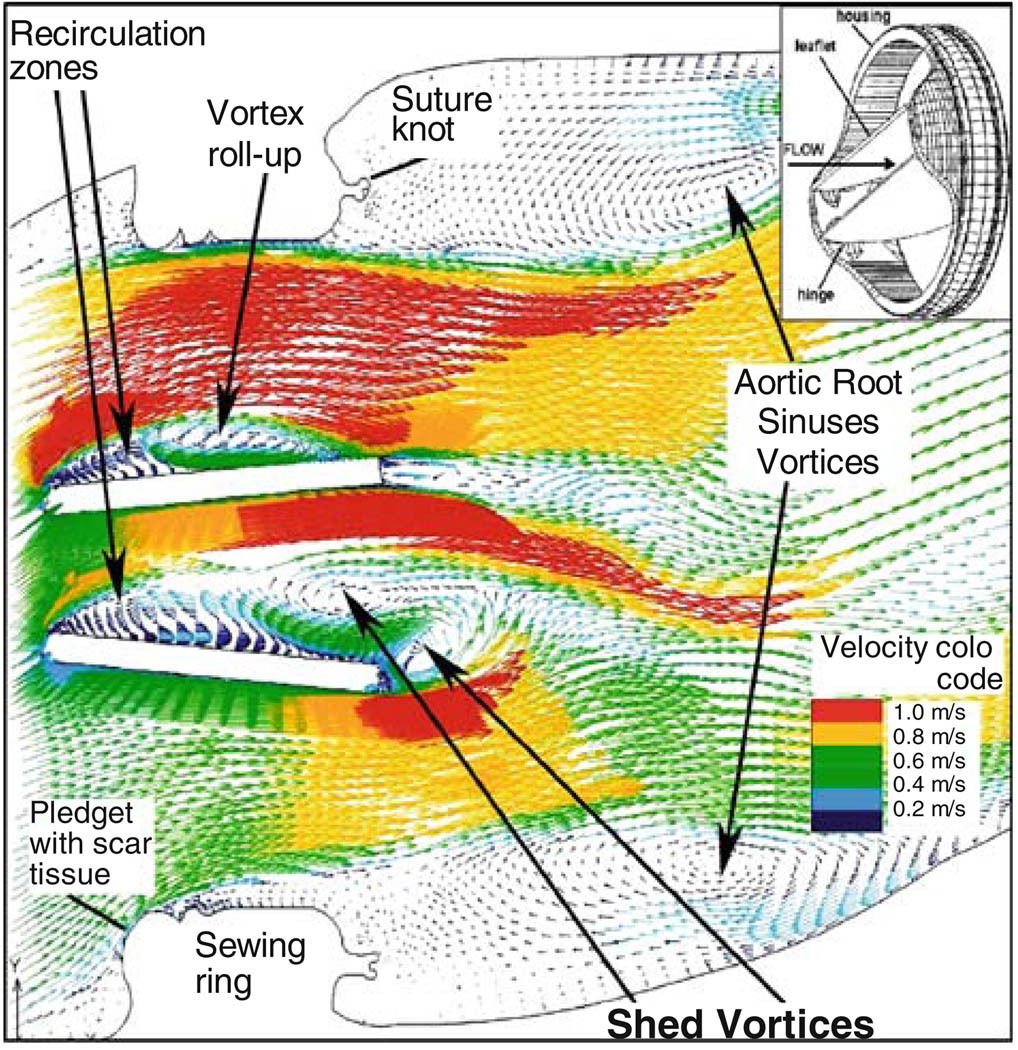
The blood flow dynamics through an aortic bileaflet MHV (St. Jude Medical) during the flow deceleration phase following peak systole, that contribute to platelet activation and thromboemboli formation, are depicted in Fig. 1. The MHV is shown after aortic valve replacement (AVR).12 The Reynolds-averaged Navier–Stokes (URANS) equations were solved with non-Newtonian blood properties using the Wilcox k–ω turbulence model which is primarily intended for simulating globally low-Re internal flows (intermittent turbulent flows in the transitional range). The simulation depicts the intricate dynamics of the shed vortices that appear in the wake of the valve leaflets during the deceleration phase after peak systole, and are postulated to be a major source of free emboli formation, enhancing the risk of cardioembolic stroke. The complex flow patterns generated in the wake of the valve provide conditions that promote the formation of large platelet aggregates. Previous numerical results were validated with Digital Particle Image Velocimetry.15
FIGURE 1.
Flow field through St. Jude bileaflet MHV (196 ms after peak systole).
Turbulent particle paths were computed using a Lagrangian approach of particulate two-phase flow and a stochastic model simulating the interaction between turbulence and platelets.37,38 A large portion of the platelets flowing around the leaflets while exposed to elevated shear stresses were entrapped within the wake of the shed vortices. Shear stress load histories of the platelets along these trajectories were computed by a summation of the product of the total (laminar plus turbulent) shear stress (τ) by the instantaneous exposure time to this stress along the trajectory, Σ (τ × Δt)—’Level of Activation’ parameter.13 Two characteristic platelet paths computed during flow deceleration and their cumulative level of activation are shown for bileaflet and monoleaflet); one in the region of highest shear stresses near the leaflet, the other in the core flow region used as a reference lower activation level. Platelets flowing near the leaflets showed a much higher level of activation, with the bileaflet valve producing steep and rapid increase in the activation level. The level of activation was further correlated to in vitro platelet activity measurements performed in LVAD.94
FSI Simulations
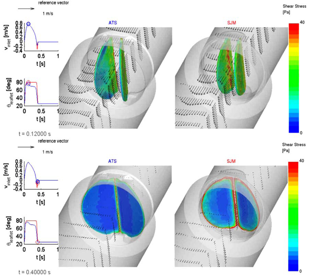
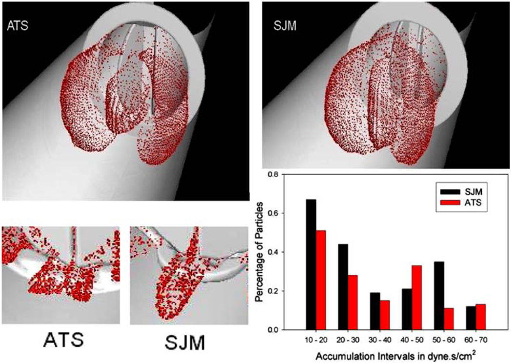
Platelet damage models were incorporated into a Fluid Structure Interaction (FSI) simulation, where the thrombogenic potential of two MHV: ATS and the SJM Regent were compared. The detailed geometric features of the valves superstructures (including the hinges) were incorporated.29 The flow fields at peak systole (T = 0.120 s) and during regurgitation (closed leaflets) are depicted in Fig. 2, with wall shear stress distributions superimposed on the leaflets, indicating higher values for the SJM valve during both the forward flow and regurgitation phases. The thrombogenic potential of each valve was then calculated by computing the platelet stress accumulation over trajectories of 15,000 particles. Platelets dispersion patterns during peak systole and regurgitant flow through the hinges (valve closed) are depicted in Fig. 3. Their corresponding activation accumulation intervals (as bar charts of low and high ranges), clearly indicate that the SJM MHV is activating more platelets. This serves to demonstrate the robustness of the numerical methodology in showing how small design changes (open pivot hinge ATS valve design as compared to the SJM ‘ear’ hinge design) translates into different thrombogenic potential for the valve.
FIGURE 2.
FSI simulation comparing SJM and ATS valves. Vector flow fields and wall shear stresses on the leaflets are shown during peak systole (top) and regurgitation (bottom).
FIGURE 3.
Platelet dispersion patterns during peak systole (top) and hinges regurgitation (bottom). Different hinge mechanism design translate into higher thrombogenic potential for the SJM valve during regurgitation.
DNS Simulations
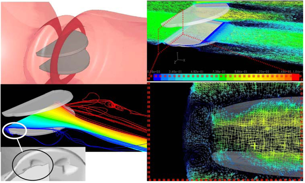
Recently we have been conducting DNS (Direct Numerical Simulations) of blood flow past St. Jude MHV. While requiring significant computational resources, DNS liberate from the need to use complex and approximate turbulence models by resolving the grid below the smallest Kolmogorov turbulent scales (in the range of 20–70 µm in MHV flows, 47 µm in a recent publication34). The highly resolved grid consisted of 17 × 106 finite volumes (40 µm). Results of these breakthrough simulations depicted an intricate pattern of counter rotating helical vortices in the gap clearance (between the leaflet pivot and the valve housing recess) of the MHV (Fig. 2). The intricate dynamics of the shed vortices in the wake of the valve during the deceleration phase after peak systole are depicted by 3D turbulent trajectories (Fig. 4). 3D helical vortices are formed entrain fluid span-wise from the leaflet leading edge into the wake of shed vortices. Those trap potentially activated platelets, enhancing thromboemboli formation.
FIGURE 4.
DNS simulations of blood flow through St. Jude MHV, showing complex platelet trajectories following helical pattern of counter rotating vortices in the hinges region (zoom in, bottom right).
Platelet Activity State (PAS) Assay for Measuring Thrombogenic Potential in Devices
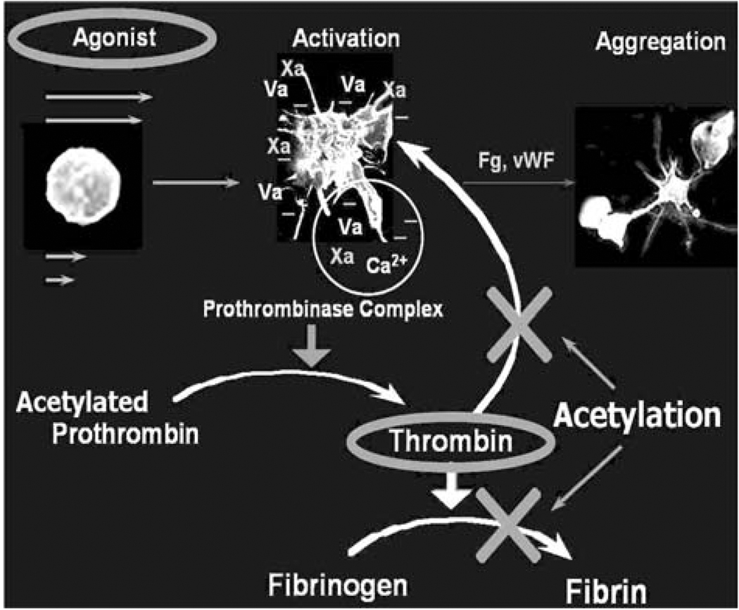
The thrombogenic potential of various PHV was tested in LVAD using the Platelet Activity State (PAS) assay,51 and was successfully applied to study platelet activity in pathological cardiovascular flow fields and PHV.10,11,13,14,16,94 The PAS assay is an innovative technique, based on a modified prothrombinase assay.51 The prothrombinase complex that activates prothrombin to thrombin in coagulation assembles on the activated platelet surface. It consists of factor Xa bound to the two essential cofactors provided by the activated platelet: Va, and anionic phospholipids.52 Acetylated prothrombin reacts with the prothrombinase complex to produce a thrombin species that does not activate platelets or clot fibrinogen. The removal of the positive feedback activation by thrombin (Fig. 5) is essential for measuring low-level flow-induced platelet activation. It results in easily measurable linear thrombin generation that accurately reflect the platelets procoagulant activity, while segregating flow-induced contributions to the hemostatic response. In this way a one-to-one correspondence is established between the agonist (flow-induced platelet activation) and the resulting platelets procoagulant activity, i.e., thrombin generation.
FIGURE 5.
PAS assay: platelets prothrombinase activity, and the effect of prothrombin acetylation-eliminating the feedback loop elimination.
Effects of Different MHV Designs
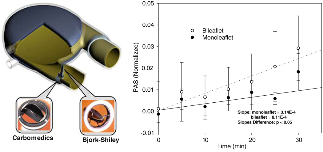
Platelets were recirculated in LVAD40 (Fig. 6), mounted with Carbomedics bileaflet and Bjork–Shiley monoleaflet MHV. Their activity was measured using an innovative Platelet Activity State (PAS) assay. The measurements indicated that the Carbomedics bileaflet MHV activated platelets at a rate of more than 2-fold than the Bjork–Shiley monoleaflet MHV (Fig. 6), indicating that the latter is less prone to thromboembolic complications.94 These measurements were in complete agreement with the numerical predictions of differences in platelet activation between the same valves, as described above.
FIGURE 6.
In vitro platelet activity measurements in LVAD: the bileaflet MHV generated higher platelet activity than the monoleaflet MHV (p<0.05).
The Device Thrombogenicity Emulator (DTE) Methodology Using a Hemodynamic Shearing Device (HSD)
An effective methodology for testing and optimizing device thrombogenic performance is presented, in which a thrombogenicity predictive technology is developed to facilitate a reduction of the device flow-induced thrombogenicity. This methodology involves a Device Thrombogenicity Emulator (DTE) depicted in Fig. 7 that replicates device hemodynamics with great accuracy according to advanced numerical simulations of blood flow in the device, and measures its thrombogenicity using a platelet activity state (PAS) assay capable of near real time and highly sensitive measurements of flow-induced platelet hemostatic activity in devices. Specifically, it combines stress loading waveforms extracted from detailed numerical flow simulations that are programmed into a computer-controlled, hemodynamics-emulating device (Hemodynamic Shearing Device—HSD), and the platelet activity state measurements. It will be capable of predicting the effect of design modifications aimed specifically at reducing device thrombogenicity. Rather than refabricating and testing the entire device, the DTE emulates the hemodynamics in ‘hot spots’ regions of a CVS device and then test whether specific design modifications (conducted in the virtual numerical domain, then replicated in the HSD where their effects are tested in vitro) achieve a desired level of thrombogenicity reduction. The universal nature of the system gives the technology an unparalleled degree of freedom for testing and redesigning almost any type of device.
FIGURE 7.
The DTE methodology: platelet trajectories and their loading history in MHV flow serve to generate input waveforms to the Hemodynamic Shearing Device (HSD).
Several DTE prototypes are currently tested for predicting the thrombogenic potential of various subgroups of CVS devices: Prosthetic Heart Valves (PHV) and Ventricular Assist Device (VAD). PHV offer some of the most complex flow fields in CVS devices and thus a real challenge for optimizing their thrombogenic performance. They serve accordingly as an excellent test bed for assessing the proposed methodology. In the first stage of the DTE methodology, a detailed numerical modeling of the flow field through devices is performed. Specifically, several PHV designs: Mechanical Heart Valves (MHV), polymeric valves, and bioprosthetic valves are studied, as well as a pulsatile VAD. The models include highly resolved device geometries for studying small-scale flow phenomena in regions leading to thromboembolism. Sophisticated turbulence and fluid/structure interaction (FSI) models and damage accumulation models are employed.
In the first stage, the ‘hot spot’ regions that may lead to device thrombogenicity during distinct flow phases are identified, and flow trajectories within these regions that expose platelets to elevated stresses and potentially lead them towards activation are computed. The spatial–temporal stress distribution along the pertaining trajectories are extracted, and applied as stress loading waveforms that are programmed into the HSD. This bench top system combines the features of cone and plate and Couette viscometers, and is designed with a special consideration to ensure that the shear stress is uniform throughout the device. The HSD is programmed by translating the load waveforms computed along the pertinent trajectories in the device flow field to a dynamically changing cone spinning input waveform, accurately replicating the shear stress history along the platelet trajectory and uniformly exposing an entire platelet population in the HSD to this stress history. The HSD loaded with a platelet buffer is operated inside an incubator. Access ports are used to introduce reagents and easy removal of multiple samples. Platelet activity measurements are performed on timed aliquots removed from the system using the platelet activity state (PAS) assay.
In a blood recirculating device there is no a priori knowledge of the individual stress histories that platelets are subjected to during the ensuing passages in the device. In the HSD on the other hand, the entire platelet population is uniformly exposed to a known prescribed dynamic shear stress waveforms obtained from the simulations. In this way the HSD serves to accentuate minute effects of design modifications on platelet activity. The design optimization for a specific device type follows an iterative process, where geometric optimization is re-iterated in the modeling phase, and the new design tested in the HSD. The HSD replicates the flow conditions within the optimized design, and the new thrombogenic potential is measured. The optimized design will then be manufactured and tested in the LVAD system to show whether it achieved a reduction in its thrombogenic potential. This optimization methodology may become an essential tool for manufacturers that seek to create, redesign, and test blood recirculating cardiovascular devices. Besides reducing R&D costs, it may prevent unfortunate situations where devices need to be recalled or clinical trials stopped, because of unacceptable thrombogenicity levels—situations that could be catastrophic to patients and with devastating financial costs to society and device manufacturers alike. It is envisioned that it will also facilitate the use of these devices for long-term therapy by reducing the need for difficult pharmacological management with anticoagulants, which is mandated for most existing devices.
NUMERICAL SIMULATIONS OF MHV CLOSING DYNAMICS AND PLATELET ACTIVATION
(Chandran, K. B., Udaykumar, H. S., Lu, J., Vigmostad, S.)
MHV Closing Dynamics
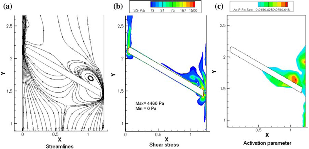
As described before, the closing dynamics of MHV illustrate the high velocities and elevated shear stresses that the formed elements are being subjected to, during the flow through the gaps at the instant of valve closure that has the potential to activate the platelets. The flow through the gap clearance at the instant of valve closure and subsequent rebound of the occluder may also promote initiation of thrombi. Typical plots of the flow stream lines, the shear stress distribution and the platelet activation parameter computed for flow through the gap width of a typical bi-leaflet valve at the instant of valve closure is shown in Fig. 8. Local mesh refinement in the computational algorithm has resulted in highly resolved flow through the gap region at the instant of valve closure exhibiting relatively high shear flows through the gap in which the platelets can be potentially activated and the activated platelets can get trapped in the vortical flow near the leaflet that can encourage aggregation and adhesion of the platelets to the surface of the leaflets. The platelet activation parameter (the fluid shear stress–time integral that the particles are subjected to, Fig. 8c) indicates a region of increased potential for platelet activation behind the occluder, where a jet-like flow passing through the gap forms a recirculation zone (Fig. 8a). Similar dynamic analysis of flow through a 2D hinge geometry of a bi-leaflet valve has also demonstrated that the hinge region presents another potential region where the platelets can get activated and subsequently remain in this region to be deposited on the valve structures.41
FIGURE 8.
Plots of (a) stream lines; (b) shear stress contours; and (c) simulated platelet activation parameter for the flow dynamics in the gap width between the leaflet edge and the valve housing for a bi-leaflet mechanical valve at the instant of valve closure.
Red Blood Cell (RBC)/Platelet Interaction Analysis
Both the simulations of the MHV forward flow and closing phase dynamic analysis described above are based on organ-level scale simulation with the assumption of the fluid as a continuum. The analysis for the potential for the platelets to be activated is based on the assumption that the bulk fluid viscous or turbulent shear stresses are directly transmitted to the platelets in this region. Such an assumption ignores the interaction between the relatively large number of RBCs (95% of formed elements) and platelets (4.9% of formed elements) in the region of such stresses. In addition, the analysis of flow dynamics during the closing phase of MHV dynamics involves analysis of flow in gap widths of 100 µm and the gap width is of the same order of that of the diameter of the RBC (~8 µm). Hence the continuum assumption breaks down in this region as well.
The platelet dynamic analysis employed in these calculations assumes that the point particles representing the platelets move with the same velocity of that of the fluid and particle–particle and particle–surface interactions are neglected. In the one-way coupling assumption employed, the effect of the formed elements on the fluid is also neglected. Thus, the organ level simulations are able to predict regions of relatively high fluid-induced stresses and predicted regions of thrombus deposition that correlates well with the regions observed with thrombus formation with implanted MHVs. Several experimental studies have demonstrated that, at the micro-scale level, increase in the number of RBCs in flow results in the margination of the platelets to the boundary region of the flow regime with the RBCs cluttering towards the core region of flow.1,30,90 In order to determine the mechanical basis for platelet activation in such flow fields, a micro-scale simulation with a detailed analysis of particulate interaction is essential. Towards this end, a first generation micro-scale analysis simulating the RBC/platelet interaction in a flow field has been recently reported.4 In this model, 2D flow dynamics of RBCs simulated as 8 µm ellipsoid semi-rigid elastic solid and platelets simulated as rigid 2 µm discoids was analyzed. Collision and translation of the particles within the steady flow field of Newtonian fluid (plasma) was computed with the location of the solids identified at every instant using the level-set algorithm. The analysis was restricted to low Reynolds number flows with the hematocrit limited to below 15% in the initial attempt on the development of the micro-scale analysis for RBC/platelet interaction.
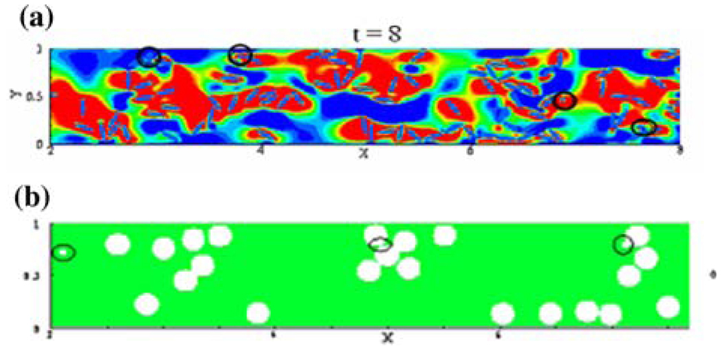
The analysis showed that the platelets were marginated to the boundaries where as the RBCs tend to move towards the core flow region, agreeing with the previous experimental studies. Furthermore, the computations also showed that the platelets in the flow field experienced significantly higher shear forces than the bulk fluid shear, and this effect was due to the fluid streaming between particles when they move close to each other immediately before or after collision. It was also further determined that the shear forces experienced by the platelets increased with increase in the number of RBCs (hematocrit) within the range of hematocrits studied in the model. Furthermore, this analysis showed that the relative size of the RBCs was more important in the interaction among the particles rather than the ellipsoid shape. Figure 9 depicts the margination of the platelets in the flow field with the ellipsoid (Fig. 9a) or cylindrical (Fig. 9b) shaped RBCs of 8 µm in diameter. During the initial efforts on the micro-scale simulation, the analysis was restricted to low Reynolds number flows and with the hematocrit magnitudes restricted to less than 15%. The RBCs were also assumed to be semi-rigid solids and more realistic simulation requires the analysis with a fluid-filled flexible membranous cells interacting with relatively rigid platelets. Efforts are continuing on the parallelization of the code and improved computational algorithms in order to analyze the micro-scale dynamics to physiologically realistic flow and hematocrit ranges.
FIGURE 9.
Micro-scale analysis of RBC/platelet interaction in a channel with a width of 42 µm.
Need for Multi-Scale Simulation
Although the flow in narrow gap widths can be resolved accurately with local mesh refinement in the simulation of flow dynamics past MHVs in the organ level simulation, it is impractical to perform micro-scale computations for the entire flow field at the organ-level dimensions. Micro-scale analysis of the detailed interaction between RBCs and platelets demonstrates that the forces transmitted to the platelets are significantly higher than the bulk shear stress computed in the flow fields. Hence the application of particle dynamic analysis with one-way coupling and the computation of the integral of the bulk shear stress that the particles are subjected to and the duration as a measure of platelet activation may not provide an accurate depiction of the behavior of the platelets in such flow fields. For example, in the high shear flow field in the gap between the leaflet edge and valve housing with MHVs (and similarly in the hinge regions of bi-leaflet valves), detailed computation of the interaction between the RBCs and platelets is necessary to understand the mechanics related to the activation of platelets. One alternative to resolve the behavior of platelets in flow past cardiovascular implants is to develop multi-scale simulation strategies. One possible approach to the problem is to develop the detailed flow dynamic analysis for the valve dynamics at the organ level that includes highly resolved flow dynamics solution with FSI analysis in the three-dimensional geometry. Regions of interest such as with high shear flow fields can be identified with such an analysis and the micro-scale analysis is then performed in the ‘zoomed in’ region of interest for the detailed dynamics of RBCs and platelets.
Strategies and appropriate algorithms are in need of development for concurrent analysis at the organ level and micro-scale flow fields and appropriate transfer of information among the multi-scale analyses. Development of such multi-scale simulations will be very important in the understanding of the precise mechanism for platelet activation and such understanding can form the basis for design modifications to minimize the problem encountered with cardiovascular implants. Development of multi-scale simulations is an active area of algorithm development in the understanding of the biological transport phenomena ranging in spatial scale varying from organ level to sub-micron dimensions and temporal scale varying from years to nano-seconds. The reader may want to refer to the position paper “Particle-Based Methods for Multiscale Modeling of Blood Flow in the Circulation and in Devices: Challenges and Future Directions” appearing in this special issue that describes some of the particle-based methods recently adapted to tackle this challenging problem.
THE PENN STATE ARTIFICIAL HEART
(Manning, K. B., Deutsch, S., Paterson, E. G., Rosenberg, G., Weiss, W. J.)
Although ventricular assist devices (VADs) are more widely accepted as bridge-to-transplant, bridge-to-recovery and destination therapy, thromboembolic events still remain a significant problem. At the Penn State Artificial Heart Lab we have been focusing our efforts to more accurately predict when thrombus deposition would develop using experimental fluid mechanics, computational fluid dynamics, and animal studies. As part of this effort, we are developing two VADs, a 12 cc pediatric pneumatically driven VAD and a 50 cc electrically driven VAD. A review of the experimental fluid mechanics of pulsatile blood pumps, written by our group, has recently appeared.27 The fluid mechanics of the pumps has been studied since the early 1970s in an attempt to reduce hemolysis and thrombus formation by the device. The mechanical heart valves employed in the devices are the most likely cause for blood damage and platelet activation. For example, turbulent stresses in the regurgitant flow through the closed valves can easily be as large as 10,000 dyn/cm2. A major feature of all pulsatile pumps is a rotational “washing” flow in mid- to late-diastole, which is set up by a penetrating inlet jet. While flow in the pump chamber seems largely benign, and the larger pumps show little or no deposition in the chamber, low wall shear stresses throughout the pump cycle can lead to thrombus formation in the smaller pumps. Understanding of the local fluid dynamics is critical.
After analyzing a number of dimensionless parameters such as the Strouhal number, Reynolds number, and Prandtl velocity ratio that potentially could indicate the antithrombotic properties of our pulsatile VADs, we are now convinced that the most important factor for a given material and texture is wall shear stress of a given magnitude and duration. Although maintaining a non-dimensional shear stress might seem desirable, we have evidence from in vivo experiments, experimental fluid dynamics (EFD) and CFD, that a specific magnitude wall shear for a given time are the parameters that are critical in pump design. Previous work has clearly shown that simply applying fluid mechanic scaling laws has not translated well with these types of blood pumps.7 Our data also indicate that areas of low wall shear are areas prone to thrombus formation. For example it is possible to have two different size tubes that have different flow rates and the same Reynolds number but greatly different wall shear stresses. Maintaining similitude will not ensure a given magnitude wall shear stress. Rather than a similitude approach our results indicate that an approach using CFD and EFD to design a pump that has a shear stress above a value we are determining from in vivo testing is the correct approach. From Hochareon et al.,47 data show the wall strain rate as a function of time for various locations in the pumps. Comparing the strain rate history of an area where deposition occurs to an area where little or none is encountered provides valuable design data. Unlike previous studies,50 these data are taken under pulsatile conditions and compared to in vivo deposition. This approach led to pump design modifications intended to study regional flow features rather than global scaling effects. The three desirable features of the flow field in blood pumps may be summarized as: (1) no regions of stasis or prolonged residence time; (2) turbulent stresses not high enough to activate platelets; and (3) wall shear stresses that are high enough to prevent thrombus deposition on the artificial material surfaces.
The counter example to this is an early design pneumatic 15 cc pump which displayed consistent thrombus deposition on the fixed surface opposite the moving blood sac.7 Our preliminary fluid dynamic studies of this chamber showed a single wall washing vortex with no obvious signs of stasis, yet peak wall shear stresses away from the valves were less than 10 dyn/cm2, (~290 s−1) much lower than in our 70 cc chamber. In addition, the turbulence levels were lower in the 15 cc chamber (turbulent shear stresses away from the valves did not exceed 200 dyn/cm2). It therefore appears that a reduction in wall shear stresses increased thrombus adherence to the artificial surface.
50 cc Penn State Ventricular Assist Device
Particle image velocimetry (PIV) was used to quantify the local wall shear rates for correlation to thrombus deposition. Hochareon et al.47 were the first to note that the whole flow field data, provided by PIV, at any time during the cycle could be acquired rapidly enough to impact the design process, and further48 used a novel post-processing technique to provide wall shear rate data, critical to the prediction of thrombus deposition, from high magnification PIV results on the surface of the 50 cc blood sac. Using 500 s−1 as a minimum wall shear rate to prevent thrombosis on the blood sac50 enabled to predict areas of potential thrombus deposition from wall shear maps.47 The region predicted as potential locations for thrombus formation were shown to contain thrombi in the in vivo implant study using the same device.93 We also demonstrated a relationship between extremely low wall shears (~300 s−1) and visual thrombosis after bovine explant of our initial 50 cc VAD design.46
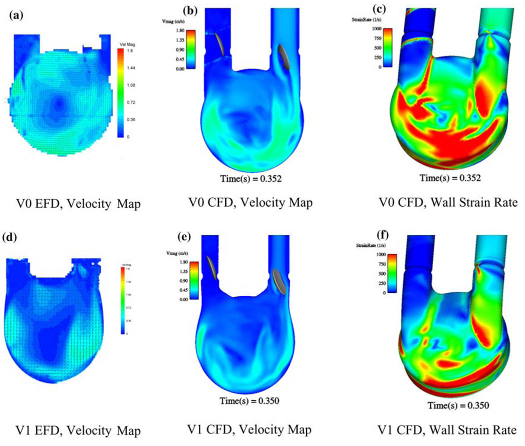
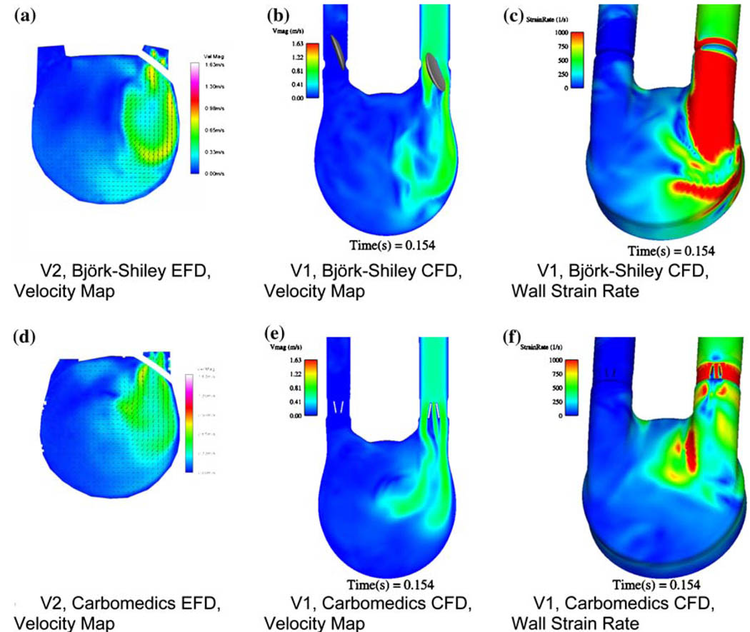
Recently, we have been developing a CFD model to predict areas prone to thrombosis within our 50 cc VAD. We have developed an unsteady three-dimensional CFD model based upon simplifying assumptions and validated it through comparisons with our PIV data.70,75 We have successfully used this model to evaluate port and chamber design (Fig. 10), valve orientation and type (Fig. 11), scale effects (50 cc vs. 70 cc vs. 15 cc), and operational parameters. The value of a combined EFD/CFD/in vivo program, as a method toward rational VAD design, is best illustrated by comparing the performance of VAD with diffrent MHV designs. The features of the inlet jet during early diastole (Fig. 11) clearly depend on the choice of valve. The inlet jet for the BSM valve penetrates further into the interior of the pump, than does the jet from the CarboMedics (CM) valve (Fig. 11). The computational shear rate maps (Figs. 11c and 11f) confirm that the BSM valve jet is stronger. Our experience tells us then, that the BSM valve will set up a stronger rotational washing flow than will the CM valve. We further plan to incorporate blood rheology in stress–strain closure models for prediction of fluid stress and associated hemolysis.
FIGURE 10.
Experimental fluid dynamics (EFD) and computational fluid dynamics (CFD) at 350 ms into diastole-port and chamber effects for V0 (a) EFD velocity, (b) CFD velocity, (c) CFD wall strain rate and V1 (d) EFD velocity, (e) CFD velocity, and (f) CFD wall strain rate.
FIGURE 11.
A comparison between EFD and CFD at 150 ms into diastole focusing on the influence of valve type for (a) V2 EFD with the BSM MHV, (b) V1 CFD with the BSM MHV, (c) V1 CFD with the BSM MHV wall strain rate, (d) V2 EFD with the CM MHV, (e) V1 CFD with the CM MHV, and (f) V1 CFD with the CM MHV wall strain rate.
12 cc Penn State Pediatric Ventricular Assist Device
As mentioned before, scaling laws are inadequate to design our smaller blood pumps. We modified our mock circulatory loop to ensure pediatric physiological flows and pressures for PIV measurements, and calculated the wall shear rate in any measurement plane over the beat cycle. Viscoelastic blood analogs provide a better representation of the flow field in pulsatile pumps than the traditionally used Newtonian ones,73 as was demonstrated in a 15 cc pediatric device,7 where larger regions of lower shear rates, more prone to clotting, were observed for the non-Newtonian fluid.
Long et al.70 developed a series of viscoelastic fluids, as a function of blood hematocrit, that are suitable for our optical measurement techniques. In Manning et al.,74 planar PIV was used to explore the flow behavior of the Penn State 12 cc pneumatic pediatric assist pump with Bjork–Shiley Monostrut 17 mm MHV, operated at 86 bpm using 40% hematocrit viscoelastic analog fluid. Wall shear maps complemented the velocity data collected. In contrast with results from the larger pumps, the flow field was highly three-dimensional during early diastole with poorer penetration by the valve inlet jet. This led to a later start of a “wall washing” rotational pattern. A significant separation region was created upstream of the outlet valve leaflet during late diastole, effectively reducing the area and increasing the pressure drop across the valve. Wall shear maps indicated regions of low shear persisting throughout the duty cycle.
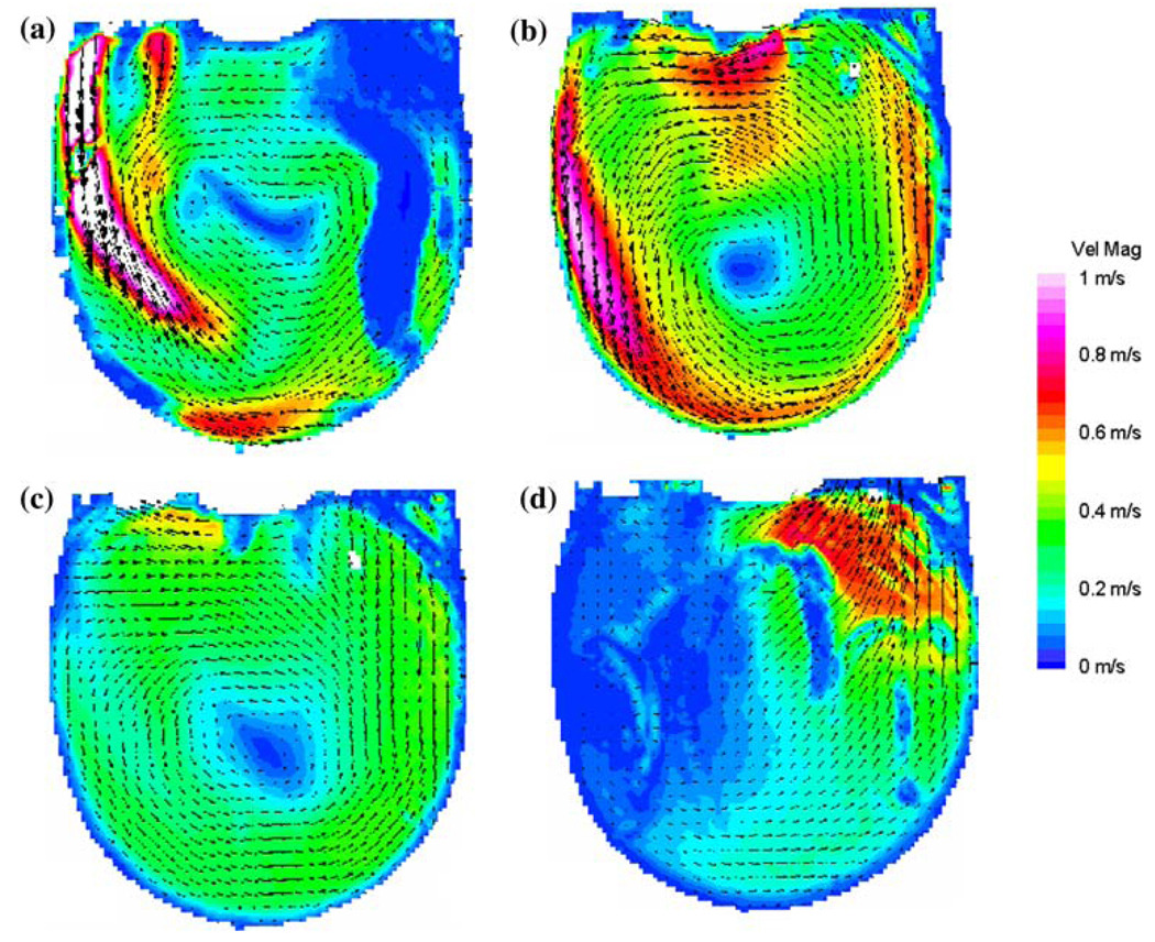
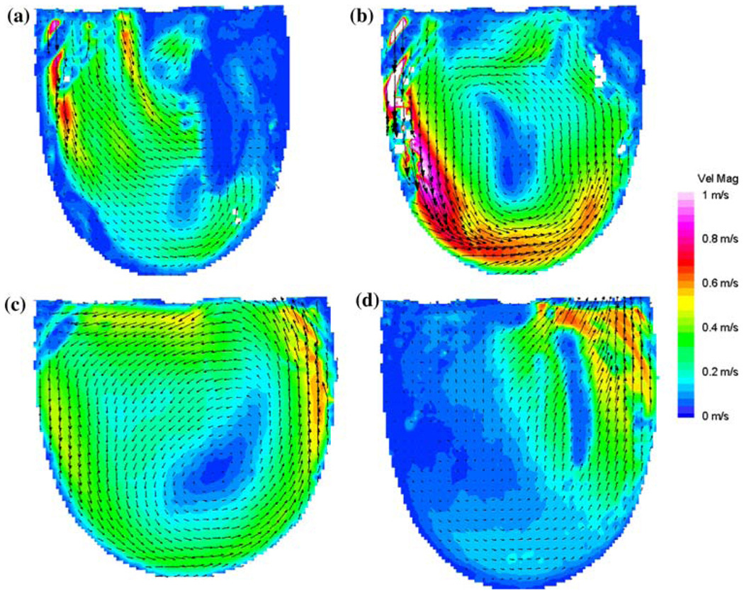
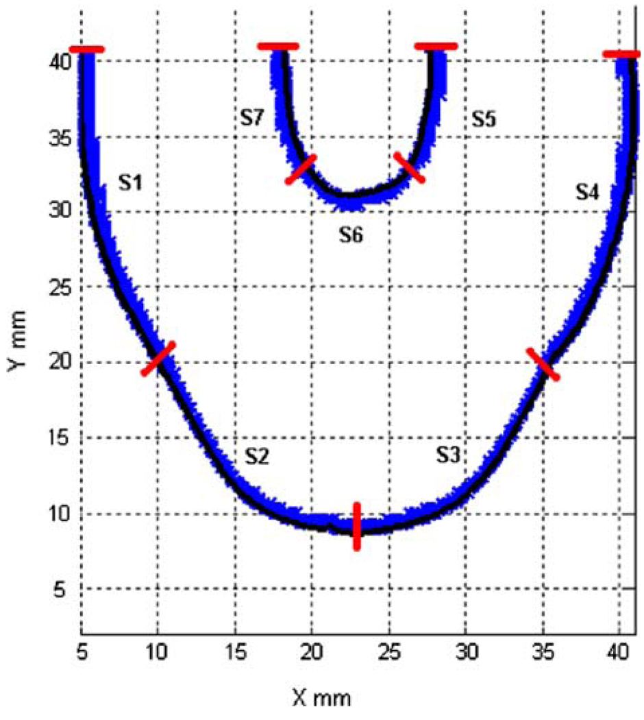
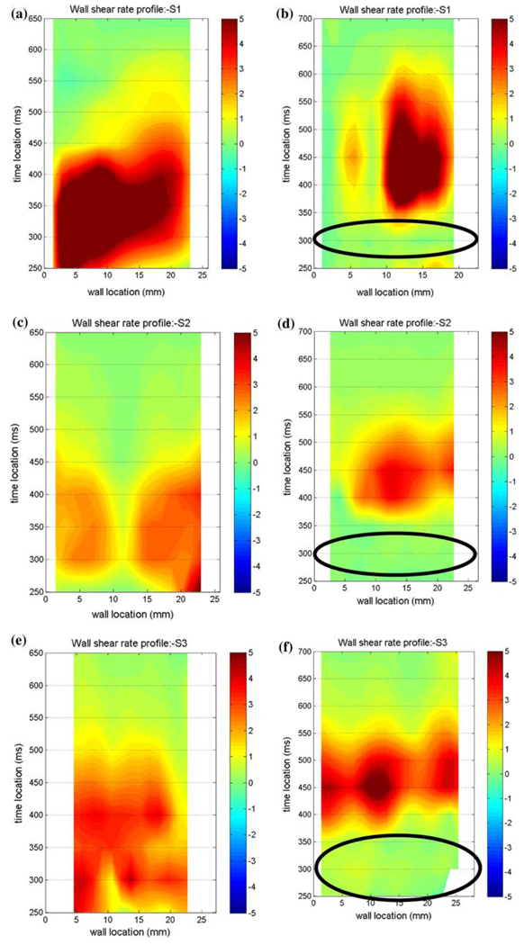
Comparative measurements were performed to determine which MHV provides the best overall flow, in the sense of ensuring an adequate wall shear to prevent large scale thrombosis. We compared the Bjork–Shiley Monostrut (BSM) tilting disc valve (17 mm) and the CarboMedics (CM) bi-leaflet valve (16 mm). Adequate wall washing was considered when wall shear rate exceeded 500 s−1 at each spatial location for a part of the cardiac cycle. The BSM valve configuration exhibits a strong major orifice jet (Fig. 12) that develops with enough momentum to provide sufficient penetration into the body of the device leading to a fully developed rotational flow pattern by 250 ms; 100 ms before the CM valve configuration (Fig. 13).24 There was also no valvular leakage associated with the BSM valves, in contrast to the heavy regurgitation seen in the CM valve configuration that can lead to blood damage. Using our wall shear calculations, we divided the walls of the device into seven sections (Fig. 14). A flood contour map was generated for each Surface for both valve configurations. The color corresponds to wall shear rate, is placed spatially (according to wall location) and temporally (according to time in the cardiac cycle) in the x and y axes, respectively, and presented normalized (by dividing by 500 s−1). Focusing in the PVAD body (11 mm plane), Surface 1 of the BSM configuration (Fig. 15a) experienced wall shear rates over 500 s−1 from 250 to 450 ms for the entire wall whereas the CM valve (Fig. 15b) showed a low shear region across most of Surface 1 during early diastole. Along Surface 2 a more significant difference in wall shear patterns between the two valve configurations is apparent (Fig. 15c and Fig. 7d). The BSM configuration shows adequate shear from 250 to 450 ms over the entire surface, while the CM valve configuration only shows wall shear rates above 500 s−1 from 400 to 500 ms. This low shear rate for most of diastole could increase the propensity of thrombus formation. Surface 3 highlights the importance of setting up an early rotational flow pattern. The BSM valve configuration (Fig. 15e) shows adequate shear rates from 250 to 550 ms, while the CM valve configuration (Fig. 15f) shows low shear until 400 ms. The strong diastolic inlet jet near the wall of the device is present from the onset of diastole in the BSM configuration, while this concentrated inlet jet does not appear until later in the cardiac cycle for the CM valve configuration. Because of this, the BSM rotational flow develops earlier and creates significant velocity near the wall of the device and results in adequate shear rates. Regurgitation through the CM valve served as a significant hindrance to the development of the rotational flow. As a result, we have selected and are using the BSM valve for the clinical device.
FIGURE 12.
Mean PIV flow maps in the 11 mm plane at (a) 250, (b) 400, (c) 550, and (d) 650 ms for the BSM valve showing the time history of the rotational flow pattern. (From Cooper et al.24 with permission).
FIGURE 13.
Mean PIV flow maps in the 11 mm plane at (a) 300, (b) 400, (c) 550, and (d) 700 ms for the CM valve configuration illustrating the time history of the rotational flow pattern. (From Cooper et al.24 with permission).
FIGURE 14.
Surface locations (S1–S7) used in wall shear calculations for both valve configurations. (From Cooper et al.24 with permission).
FIGURE 15.
Non-dimensionalized wall shear maps for the BSM (left column) and CM (right column) valve configurations in the 11 mm plane for Surface 1 (a, b), Surface 2 (c, d), and Surface 3 (e, f). Areas of interest are highlighted with ovals. Note that the wall locations are defined in a counter-clockwise fashion. (From Cooper et al.24 with permission).
We further explored how during myocardial recovery, the PVAD must be weaned from the patient to prepare for explant.83 For pulsatile devices, this often includes a reduction in flow rate, which can change the fluid dynamics of the device. These changes in flow need to be monitored because strong diastolic rotational flow, no areas of blood stasis, low blood residence time and wall shear rates above 500 s−1, can help prevent thrombus deposition. Using PIV, we observed the planar flow patterns and wall shear rates at both a normal operating condition and a reduced beat rate. At the reduced beat rate, the PVAD showed an earlier loss of rotational pattern, increased blood residence time, and an overall reduction in wall shear rate at the outer walls. Because this reduction in flow rate could lead to a possible increase in thrombus deposition, it may be necessary to look into other options for weaning a patient from the PVAD. We further explored altering operation of the PVAD during times of weaning.25 In an effort to develop a strong inlet jet and rotational flow pattern at a lower beat (50 bpm) and flow rate; we compressed diastole by altering the end-diastolic delay time (EDD). Particle image velocimetry was used to compare the flow fields and wall shear rates in the chamber of the 12 cc PVAD using EDDs of 10, 50, and 100 ms. While we expected the 100 ms end-diastolic delay to have the best wall shear profiles, however, we found that the 50 ms EDD condition was superior to both the 10 and 100 EDD conditions, due to a longer sustained inlet jet.
These experimental and computational studies provide the foundation for a methodology to improve ventricular assist devices (including pulsatile blood pumps) that still suffer from thromboembolic events. By integrating EFD and CFD during the design phase, we will help facilitate improved device performance clinically by correlating the results to in vivo animal studies. However, in vitro blood studies still need to be performed to fundamentally understand how wall shear rate and exposure time are related to thrombus deposition in pulsatile flows.
SUMMARY
The work presented in this article represents only few efforts by several groups working in the field who tackle the daunting goal of developing methodologies that may facilitate optimizing the thrombogenic performance of blood recirculating devices. This work includes state-of-the-art numerical and experimental tools used to elucidate flow-induced mechanisms leading to thromboembolism in prosthetic devices. Design of MHV and VADs is traditionally concerned with hemocompatibility, durability, and thromboresistance, with hemodynamic characteristics somewhat taking a backseat. Hemodynamic optimization is aimed at avoiding the formation of stagnant zones and regions of elevated stresses, while achieving good washout characteristics. Traditional design matrix approaches for optimizing devices are only of limited utility, as the optimization process is very specific to the device design characteristics and its inherent geometric constraints. Accordingly, in the cardiovascular device industry, designing and manufacturing device prototypes and testing them ad hoc represents a common practice.
Elucidating the hemodynamics of devices via sophisticated fluid dynamics and thrombogenic testing is far from trivial, and the identification and/or interpretation of pertinent design parameters is subtle. With the inherent design constraints of blood recirculating devices this is clearly a formidable challenge. While there are no established set of parameters for achieving design optimization, the ultimate goal is to minimize the thrombogenicity of the device—preferably to a level that will not require anticoagulation (as is the case for bioprosthetic valves for example). Clearly, a modeling approach represents an efficient way to economically test design modifications to realize whether they indeed achieve this design goal. However, it requires a numerical approach that goes beyond the common quantitative flow mapping within the device—a non-trivial undertaking to begin with, given the complexity of the geometries in devices and the complex nature of blood as a fluid. It should incorporate an accountable model that is able to provide quantitatively accurate predictions of flow-induced blood hemoastatic activation, resulting from accurately resolved flow fields within the device and the stresses they induce on the blood borne particulates. It should also be noted that a modeling approach should be coupled with an experimental approach, to validate the models predictions and ultimately to test whether the methodology developed indeed led to optimizing the thrombogenic performance of the device. The work presented here demonstrate that experimental fluid mechanics, computational fluid dynamics and in vivo studies can be linked and together, contribute towards the development of ventricular assist devices in which thrombus deposition and thromboemboli formation could be minimized. This methodology can be extrapolated to other cardiovascular prosthetic devices. It points to several directions that should be pursued in the future in order to achieve the goal for blood recirculating prosthetic devices becoming more effective as destination therapy in the future.
REFERENCES
- 1.Aarts PA, van den Broek SA, Prins GW, Kuiken GD, Sixma JJ, Heethaar RM. Blood platelets are concentrated near the wall and red blood cells, in the center in flowing blood. Arteriosclerosis. 1988;8(6):819–824. doi: 10.1161/01.atv.8.6.819. [DOI] [PubMed] [Google Scholar]
- 2.Affeld K, Goubergrits L, Kertzscher U, Gadischke J, Reininger A. Mathematical model of platelet deposition under flow conditions. Int. J. Artif. Organs. 2004;27(8):699–708. doi: 10.1177/039139880402700808. [DOI] [PubMed] [Google Scholar]
- 3.Alemu Y, Bluestein D. Flow-induced platelet activation and damage accumulation in a mechanical heart valve: numerical studies. Artif. Organs. 2007;31(9):677–688. doi: 10.1111/j.1525-1594.2007.00446.x. [DOI] [PubMed] [Google Scholar]
- 4.AlMomani T, Udaykumar HS, Marshall JS, Chandran KB. Micro-scale dynamic simulation of erythrocyte-platelet interaction in blood flow. Ann. Biomed. Eng. 2008;36(6):905–920. doi: 10.1007/s10439-008-9478-z. [DOI] [PubMed] [Google Scholar]
- 5.Apel J, Neudel F, Reul H. Computational fluid dynamics and experimental validation of a microaxial blood pump. ASAIO J. 2001;47(5):552–558. doi: 10.1097/00002480-200109000-00031. [DOI] [PubMed] [Google Scholar]
- 6.Apel J, Paul R, Klaus S, Siess T, Reul H. Assessment of hemolysis related quantities in a microaxial blood pump by computational fluid dynamics. Artif. Organs. 2001;25(5):341–347. doi: 10.1046/j.1525-1594.2001.025005341.x. [DOI] [PubMed] [Google Scholar]
- 7.Bachmann CHG, Rosenberg G, Deutsch S, Fontaine A, Tarbell JM. Fluid dynamics of a pediatric ventricular assist device. Artif. Organs. 2000;24:362–372. doi: 10.1046/j.1525-1594.2000.06536.x. [DOI] [PubMed] [Google Scholar]
- 8.Bludszuweit C. Model for a general mechanical blood damage prediction. Artif. Organs. 1995;19(7):583–589. doi: 10.1111/j.1525-1594.1995.tb02385.x. [DOI] [PubMed] [Google Scholar]
- 9.Bludszuweit C. Three-dimensional numerical prediction of stress loading of blood particles in a centrifugal pump. Artif. Organs. 1995;19(7):590–596. doi: 10.1111/j.1525-1594.1995.tb02386.x. [DOI] [PubMed] [Google Scholar]
- 10.Bluestein D. Stent-induced thromboembolism. Ann. Biomed. Eng. 2000;28(3):346–350. doi: 10.1114/1.265. [DOI] [PubMed] [Google Scholar]
- 11.Bluestein D, Gutierrez C, Londono M, Schoephoerster RT. Vortex shedding in steady flow through a model of an arterial stenosis and its relevance to mural platelet deposition. Ann. Biomed. Eng. 1999;27(6):763–773. doi: 10.1114/1.230. [DOI] [PubMed] [Google Scholar]
- 12.Bluestein D, Li YM, Krukenkamp IB. Free emboli formation in the wake of bi-leaflet mechanical heart valves and the effects of implantation techniques. J. Biomech. 2002;35(12):1533–1540. doi: 10.1016/s0021-9290(02)00093-3. [DOI] [PubMed] [Google Scholar]
- 13.Bluestein D, Niu L, Schoephoerster RT, Dewanjee MK. Fluid mechanics of arterial stenosis: relationship to the development of mural thrombus. Ann. Biomed. Eng. 1997;25(2):344–356. doi: 10.1007/BF02648048. [DOI] [PubMed] [Google Scholar]
- 14.Bluestein D, Niu L, Schoephoerster RT, Dewanjee MK. Steady flow in an aneurysm model: correlation between fluid dynamics and blood platelet deposition. J. Biomech. Eng. 1996;118(3):280–286. doi: 10.1115/1.2796008. [DOI] [PubMed] [Google Scholar]
- 15.Bluestein D, Rambod E, Gharib M. Vortex shedding as a mechanism for free emboli formation in mechanical heart valves. J. Biomech. Eng. 2000;122(2):125–134. doi: 10.1115/1.429634. [DOI] [PubMed] [Google Scholar]
- 16.Bluestein D, Yin W, Affeld K, Jesty J. Flow-induced platelet activation in a mechanical heart valve. J. Heart Valve Dis. 2004;13(3):501–508. [PubMed] [Google Scholar]
- 17.Bluestein M, Mockros LF. Hemolytic effects of energy dissipation in flowing blood. Med. Biol. Eng. 1969;7(1):1–16. doi: 10.1007/BF02474665. [DOI] [PubMed] [Google Scholar]
- 18.Buchanan JR, Jr, Kleinstreuer C, Comer JK. Rheological effects on pulsatile hemodynamics in a stenosed tube. Comput. Fluids. 2000;29(6):695–724. [Google Scholar]
- 19.Burgreen GW, Antaki JF, Griffith BP. A design improvement strategy for axial blood pumps using computational fluid dynamics. ASAIO J. 1996;42(5):M354–M360. doi: 10.1097/00002480-199609000-00010. [DOI] [PubMed] [Google Scholar]
- 20.Burgreen GW, Antaki JF, Wu ZJ, Holmes AJ. Computational fluid dynamics as a development tool for rotary blood pumps. Artif. Organs. 2001;25(5):336–340. doi: 10.1046/j.1525-1594.2001.025005336.x. [DOI] [PubMed] [Google Scholar]
- 21.Chandran KB, Lee CS, Aluri S, Dellsperger KC, Schreck S, Wieting DW. Pressure distribution near the occluders and impact forces on the outlet struts of Bjork-Shiley convexo-concave valves during closing. J. Heart Valve Dis. 1996;5(2):199–206. [PubMed] [Google Scholar]
- 22.Cheng R, Lai YG, Chandran KB. Three-dimensional fluid-structure interaction simulation of bileaflet mechanical heart valve flow dynamics. Ann. Biomed. Eng. 2004;32(11):1471–1483. doi: 10.1114/b:abme.0000049032.51742.10. [DOI] [PMC free article] [PubMed] [Google Scholar]
- 23.Cheng R, Lai YG, Chandran KB. Two-dimensional fluid-structure interaction simulation of bileaflet mechanical heart valve flow dynamics. J. Heart Valve Dis. 2003;12(6):772–780. [PubMed] [Google Scholar]
- 24.Cooper BT, Roszelle BN, Long TC, Deutsch S, Manning KB. The 12 cc Penn State pulsatile pediatric ventricular assist device: fluid dynamics associated with valve selection. J. Biomech. Eng. 2008;130:041019. doi: 10.1115/1.2939342. [DOI] [PubMed] [Google Scholar]
- 25.Cooper BT, Roszelle BN, Long TC, Deutsch S, Manning KB. The influence of operational protocol on the fluid dynamics in the 12 cc Penn State pulsatile pediatric ventricular assist device: the effect of end-diastolic delay. Artif. Organs. 2010 doi: 10.1111/j.1525-1594.2009.00852.x. (in press) [DOI] [PMC free article] [PubMed] [Google Scholar]
- 26.David T, Thomas S, Walker PG. Platelet deposition in stagnation point flow: an analytical and computational simulation. Med. Eng. Phys. 2001;23(5):299–312. doi: 10.1016/s1350-4533(01)00047-9. [DOI] [PubMed] [Google Scholar]
- 27.Deutsch S, Tarbell JM, Manning KB, Rosenberg G, Fontaine AA. Experimental fluid mechanics of pulsatile artificial blood pumps. Annu. Rev. Fluid Mech. 2006;38:65–86. [Google Scholar]
- 28.Dowling RD, Etoch SW, Stevens KA, Johnson AC, Gray LA., Jr Current status of the Abio-Cor implantable replacement heart. Ann. Thorac. Surg. 2001;71(3 Suppl):S147–S149. doi: 10.1016/s0003-4975(00)02615-1. discussion S183–S144. [DOI] [PubMed] [Google Scholar]
- 29.Dumont K, Vierendeels J, van Nooten G, Verdonck P, Bluestein D. Comparison of ATS open pivot valve and St Jude Regent Valve using a CFD model based on fluid-structure interaction. J. Biomech. Eng. 2007;129(4) doi: 10.1115/1.2746378. [DOI] [PubMed] [Google Scholar]
- 30.Eckstein EC, Bilsker DL, Waters CM, Kippenhan JS, Tilles AW. Transport of platelets in flowing blood. Ann. N. Y. Acad. Sci. 1987;516:442–452. doi: 10.1111/j.1749-6632.1987.tb33065.x. [DOI] [PubMed] [Google Scholar]
- 31.El-Banayosy A, Korfer R, Arusoglu L, Kizner L, Morshuis M, Milting H, Tenderich G, Fey O, Minami K. Device and patient management in a bridge-to-transplant setting. Ann. Thorac. Surg. 2001;71(3 Suppl):S98–S105. doi: 10.1016/s0003-4975(00)02618-7. discussion S114–S105. [DOI] [PubMed] [Google Scholar]
- 32.Fogelson AL, Wang NT. Platelet dense-granule centralization and the persistence of ADP secretion. Am. J. Physiol. 1996;270(3 Pt 2):H1131–H1140. doi: 10.1152/ajpheart.1996.270.3.H1131. [DOI] [PubMed] [Google Scholar]
- 33.Garon A, Farinas M-I. Fast three-dimensional numerical hemolysis approximation. Artif. Organs. 2004;28(11):1016–1025. doi: 10.1111/j.1525-1594.2004.00026.x. [DOI] [PubMed] [Google Scholar]
- 34.Ge L, Dasi LP, Sotiropoulos F, Yoganathan AP. Characterization of hemodynamic forces induced by mechanical heart valves: Reynolds vs. viscous stresses. Ann. Biomed. Eng. 2008;36(2):276–297. doi: 10.1007/s10439-007-9411-x. [DOI] [PubMed] [Google Scholar]
- 35.Ge L, Jones SC, Sotiropoulos F, Healy TM, Yoganathan AP. Numerical simulation of flow in mechanical heart valves: grid resolution and the assumption of flow symmetry. J. Biomech. Eng. 2003;125(5):709–718. doi: 10.1115/1.1614817. [DOI] [PubMed] [Google Scholar]
- 36.Ge L, Leo HL, Sotiropoulos F, Yoganathan AP. Flow in a mechanical bileaflet heart valve at laminar and near-peak systole flow rates: CFD simulations and experiments. J. Biomech. Eng. 2005;127(5):782–797. doi: 10.1115/1.1993665. [DOI] [PubMed] [Google Scholar]
- 37.Gosman A, Ioannides L. Aspects of compuer simulation of liquid-fueled cumbustors; AIAA 19th Aerospace Science Meeting, 81-0323.1981. [Google Scholar]
- 38.Gosman A, Ioannides L. Aspects of computer simulation of liquid-fuelled combustors. AIAA J. Energy. 1983;7(6):482–490. [Google Scholar]
- 39.Goubergrits L, Affeld K. Numerical estimation of blood damage in artificial organs. Artif. Organs. 2004;28(5):499–507. doi: 10.1111/j.1525-1594.2004.07265.x. [DOI] [PubMed] [Google Scholar]
- 40.Goubergrits L, Affeld K, Kertzscher U. Innovative developments of the heart valves designed for use in ventricular assist devices. Expert Rev. Med. Devices. 2005;2(1):61–71. doi: 10.1586/17434440.2.1.61. [DOI] [PubMed] [Google Scholar]
- 41.Govindarajan V, Udaykumar HS, Chandran KB. Two-dimensional simulation of flow and platelet dynamics in the hinge region of a mechanical heart valve. J. Biomech. Eng. 2009;131:031002-1–031002-12. doi: 10.1115/1.3005158. [DOI] [PMC free article] [PubMed] [Google Scholar]
- 42.Grosset DG, Georgiadis D, Kelman AW, Cowburn P, Stirling S, Lees KR, Faichney A, Mallinson A, Quin R, Bone I, Pettigrew L, Brodie E, MacKay T, Wheatley DJ. Detection of microemboli by transcranial Doppler ultrasound. Tex. Heart Inst. J. 1996;23(4):289–292. [PMC free article] [PubMed] [Google Scholar]
- 43.Guezuraga RM, Steinbring DY. View from industry. Eur. J. Cardiothorac. Surg. 2004;26 Suppl 1:S19–S26. discussion S23–S26. [PubMed] [Google Scholar]
- 44.Harker LA, Slichter SJ. Studies of platelet and fibrinogen kinetics in patients with prosthetic heart valves. N. Engl. J. Med. 1970;283(24):1302–1305. doi: 10.1056/NEJM197012102832402. [DOI] [PubMed] [Google Scholar]
- 45.Healy TM, Ellis JT, Fontaine AA, Jarrett CA, Yoganathan AP. An automated method for analysis and visualization of laser Doppler velocimetry data. Ann. Biomed. Eng. 1997;25(2):335–343. doi: 10.1007/BF02648047. [DOI] [PubMed] [Google Scholar]
- 46.Hochareon PMK, Fontaine AA, Tarbell JM, Deutsch S. Correlation of in vivo clot deposition with the flow characteristics in the 50 cc Penn state artificial heart: a preliminary study. ASAIO J. 2004;50:537–542. doi: 10.1097/01.mat.0000145694.40637.a0. [DOI] [PubMed] [Google Scholar]
- 47.Hochareon PMK, Fontaine AA, Tarbell JM, Deutsch S. Fluid dynamic analysis of the 50 cc Penn State artificial heart under physiological operating conditions using particle image velocimetry. J. Biomech. Eng. 2004;126:585–593. doi: 10.1115/1.1798056. [DOI] [PubMed] [Google Scholar]
- 48.Hochareon PMK, Fontaine AA, Tarbell JM, Deutsch S. Wall shear-rate estimation within the 50 cc Penn State artificial heart using particle image velocimetry. J. Biomech. Eng. 2004;126:430–437. doi: 10.1115/1.1784477. [DOI] [PubMed] [Google Scholar]
- 49.Huang ZJ, Merkle CL, Abdallah S, Tarbell JM. Numerical simulation of unsteady laminar flow through a tilting disk heart valve: prediction of vortex shedding. J. Biomech. 1994;27(4):391–402. doi: 10.1016/0021-9290(94)90015-9. [DOI] [PubMed] [Google Scholar]
- 50.Hubbell JAML. Visualization and analysis of mural thrombogenesis on collagen, polyurethane and nylon. Biomaterials. 1986;7:354–363. doi: 10.1016/0142-9612(86)90006-2. [DOI] [PubMed] [Google Scholar]
- 51.Jesty J, Bluestein D. Acetylated prothrombin as a substrate in the measurement of the procoagulant activity of platelets: elimination of the feedback activation of platelets by thrombin. Anal. Biochem. 1999;272(1):64–70. doi: 10.1006/abio.1999.4148. [DOI] [PubMed] [Google Scholar]
- 52.Jesty J, Nemerson Y. The pathways of blood coagulation. In: Beutler E, Lichtman MA, Coller BS, Kipps TJ, editors. Williams Hematology. New York: McGraw-Hill; 1995. pp. 1227–1238. Chap. 122. [Google Scholar]
- 53.Jesty J, Yin W, Perrotta P, Bluestein D. Platelet activation in a circulating flow loop: combined effects of shear stress and exposure time. Platelets. 2003;14(3):143–149. doi: 10.1080/0953710031000092839. [DOI] [PubMed] [Google Scholar]
- 54.Jin W, Clark C. Experimental investigation of unsteady flow behaviour within a sac-type ventricular assist device (VAD) J. Biomech. 1993;26(6):697–707. doi: 10.1016/0021-9290(93)90033-b. [DOI] [PubMed] [Google Scholar]
- 55.Kafesjian R, Howanec M, Ward GD, Diep L, Wagstaff LS, Rhee R. Cavitation damage of pyrolytic carbon in mechanical heart valves. J. Heart Valve Dis. 1994;3 Suppl 1:S2–S7. [PubMed] [Google Scholar]
- 56.Kawahito K, Adachi H, Ino T. Platelet activation in the gyro C1E3 centrifugal pump: comparison with the terumo capiox and the Nikkiso HPM-15. Artif. Organs. 2000;24(11):889–892. doi: 10.1046/j.1525-1594.2000.06639.x. [DOI] [PubMed] [Google Scholar]
- 57.Kelly SG, Verdonck PR, Vierendeels JA, Riemslagh K, Dick E, Van Nooten GG. A three-dimensional analysis of flow in the pivot regions of an ATS bileaflet valve. Int. J. Artif. Organs. 1999;22(11):754–763. [PubMed] [Google Scholar]
- 58.King MJ, David T, Fisher J. Three-dimensional study of the effect of two leaflet opening angles on the time-dependent flow through a bileaflet mechanical heart valve. Med. Eng. Phys. 1997;19(3):235–241. doi: 10.1016/s1350-4533(96)00066-5. [DOI] [PubMed] [Google Scholar]
- 59.Kini V, Bachmann C, Fontaine A, Deutsch S, Tarbell JM. Integrating particle image velocimetry and laser Doppler velocimetry measurements of the regurgitant flow field past mechanical heart valves. Artif. Organs. 2001;25(2):136–145. doi: 10.1046/j.1525-1594.2001.025002136.x. [DOI] [PubMed] [Google Scholar]
- 60.Kiris C, Kwak D, Rogers S, Chang ID. Computational approach for probing the flow through artificial heart devices. J. Biomech. Eng. 1997;119(4):452–460. doi: 10.1115/1.2798293. [DOI] [PubMed] [Google Scholar]
- 61.Klaus S, Korfer S, Mottaghy K, Reul H, Glasmacher B. In vitro blood damage by high shear flow: human versus porcine blood. Int. J. Artif. Organs. 2002;25(4):306–312. doi: 10.1177/039139880202500409. [DOI] [PubMed] [Google Scholar]
- 62.Krafczyk M, Cerrolaza M, Schulz M, Rank E. Analysis of 3D transient blood flow passing through an artificial aortic valve by Lattice-Boltzmann methods. J. Biomech. 1998;31(5):453–462. doi: 10.1016/s0021-9290(98)00036-0. [DOI] [PubMed] [Google Scholar]
- 63.Krishnan S, Udaykumar HS, Marshall JS, Chandran KB. Two-dimensional dynamic simulation of platelet activation during mechanical heart valve closure. Ann. Biomed. Eng. 2006;34(10):1519–1534. doi: 10.1007/s10439-006-9194-5. [DOI] [PubMed] [Google Scholar]
- 64.Kuharsky AL, Fogelson AL. Surface-mediated control of blood coagulation: the role of binding site densities and platelet deposition. Biophys. J. 2001;80(3):1050–1074. doi: 10.1016/S0006-3495(01)76085-7. [DOI] [PMC free article] [PubMed] [Google Scholar]
- 65.Laas J, Kleine P, Hasenkam MJ, Nygaard H. Orientation of tilting disc and bileaflet aortic valve substitutes for optimal hemodynamics. Ann. Thorac. Surg. 1999;68(3):1096–1099. doi: 10.1016/s0003-4975(99)00780-8. [DOI] [PubMed] [Google Scholar]
- 66.Laas J, Kseibi S, Perthel M, Klingbeil A, El-Ayoubi L, Alken A. Impact of high intensity transient signals on the choice of mechanical aortic valve substitutes. Eur. J. Cardiothorac. Surg. 2003;23(1):93–96. doi: 10.1016/s1010-7940(02)00677-2. [DOI] [PubMed] [Google Scholar]
- 67.Lamson TC, Rosenberg G, Geselowitz DB, Deutsch S, Stinebring DR, Frangos JA, Tarbell JM. Relative blood damage in the three phases of a prosthetic heart valve flow cycle. ASAIO J. 1993;39(3):M626–M633. [PubMed] [Google Scholar]
- 68.Lazar RM, Shapiro PA, Jaski BE, Parides MK, Bourge RC, Watson JT, Damme L, Dembitsky W, Hosenpud JD, Gupta L, Tierney A, Kraus T, Naka Y. Neurological events during long-term mechanical circulatory support for heart failure: the Randomized Evaluation of Mechanical Assistance for the Treatment of Congestive Heart Failure (REMATCH) experience. Circulation. 2004;109(20):2423–2427. doi: 10.1161/01.CIR.0000129414.95137.CD. [DOI] [PubMed] [Google Scholar]
- 69.Lee CS, Chandran KB, Chen LD. Cavitation dynamics of medtronic hall mechanical heart valve prosthesis: fluid squeezing effect. J. Biomech. Eng. 1996;118(1):97–105. doi: 10.1115/1.2795951. [DOI] [PubMed] [Google Scholar]
- 70.Long JAUA, Manning KB, Deutsch S. Viscoelasticity of pediatric blood and its implications for the testing of a pulsatile pediatric blood pump. ASAIO J. 2005;51:563–566. doi: 10.1097/01.mat.0000180353.12963.f2. [DOI] [PubMed] [Google Scholar]
- 71.Mackay TG, Georgiadis D, Grosset DG, Lees KR, Wheatley DJ. On the origin of cerebrovascular microemboli associated with prosthetic heart valves. Neurol. Res. 1995;17(5):349–352. [PubMed] [Google Scholar]
- 72.Makhijani VB, Yang HQ, Singhal AK, Hwang NH. An experimental-computational analysis of MHV cavitation: effects of leaflet squeezing and rebound. J. Heart Valve Dis. 1994;3 Suppl 1:S35–S44. discussion S44–S38. [PubMed] [Google Scholar]
- 73.Mann KADS, Tarbell JM, Geselowitz DB, Rosenberg G, Pierce WS. An experimental study of Newtonian and non-Newtonian flow dynamics in a ventricular assist device. J. Biomech. Eng. 1987;109:139–147. doi: 10.1115/1.3138656. [DOI] [PubMed] [Google Scholar]
- 74.Manning KBWB, Yang N, Fontaine A, Deutsch S. Flow behavior within the 12 cc Penn State pulsatile pediatric ventricular assist device: an experimental study of the initial design. Artif. Organs. 2008;32:442–452. doi: 10.1111/j.1525-1594.2008.00565.x. [DOI] [PubMed] [Google Scholar]
- 75.Medvitz RB, Kreider JW, Manning KB, Fontaine AA, Deutsch S, Paterson EG. Development and validation of a computational fluid dynamics methodology for simulation of pulsatile left ventricular assist devices. ASAIO J. 2007;53:122–131. doi: 10.1097/MAT.0b013e31802f37dd. [DOI] [PubMed] [Google Scholar]
- 76.NHLBI Working Group R.R.c., T. Baldwin (NHLBI) Next Generation Ventricular Assist Devices for Destination Therapy, Working Group Executive Summary. National Heart Lungs and Blood Institute; 2004. [DOI] [PubMed] [Google Scholar]
- 77.Nobili M, Sheriff J, Morbiducci U, Redaelli A, Bluestein D. Platelet activation due to hemodynamic shear stresses: damage accumulation model and comparison to in vitro measurements. ASAIO J. 2008;54(1):64–72. doi: 10.1097/MAT.0b013e31815d6898. [DOI] [PMC free article] [PubMed] [Google Scholar]
- 78.O’Brien JR. Shear-induced platelet aggregation. Lancet. 1990;335(8691):711–713. doi: 10.1016/0140-6736(90)90815-m. [DOI] [PubMed] [Google Scholar]
- 79.O’Brien JR, Salmon GP. An independent haemostatic mechanism: shear induced platelet aggregation. Adv. Exp. Med. Biol. 1990;281:287–296. doi: 10.1007/978-1-4615-3806-6_30. [DOI] [PubMed] [Google Scholar]
- 80.Paul R, Marseille O, Hintze E, Huber L, Schima H, Reul H, Rau G. In vitro thrombogenicity testing of artificial organs. Int. J. Artif. Organs. 1998;21(9):548–552. [PubMed] [Google Scholar]
- 81.Reininger CB, Lasser R, Rumitz M, Boger C, Schweiberer L. Computational analysis of platelet adhesion and aggregation under stagnation point flow conditions. Comput. Biol. Med. 1999;29(1):1–18. doi: 10.1016/s0010-4825(98)00039-0. [DOI] [PubMed] [Google Scholar]
- 82.Rose EA, Moskowitz AJ, Packer M, Sollano JA, Williams DL, Tierney AR, Heitjan DF, Meier P, Ascheim DD, Levitan RG, Weinberg AD, Stevenson LW, Shapiro PA, Lazar RM, Watson JT, Goldstein DJ, Gelijns AC. The REMATCH trial: rationale, design, and end points. Randomized Evaluation of Mechanical Assistance for the Treatment of Congestive Heart Failure. Ann. Thorac. Surg. 1999;67(3):723–730. doi: 10.1016/s0003-4975(99)00042-9. [DOI] [PubMed] [Google Scholar]
- 83.Roszelle BNCB, Long TC, Deutsch S, Manning KB. The 12 cc Penn State pulsatile pediatric ventricular assist device: flow field observations at a reduced beat rate with application to weaning. ASAIO J. 2008;54:325–331. doi: 10.1097/MAT.0b013e3181695cfe. [DOI] [PubMed] [Google Scholar]
- 84.Schima H, Muller MR, Papantonis D, Schlusche C, Huber L, Schmidt C, Trubel W, Thoma H, Losert U, Wolner E. Minimization of hemolysis in centrifugal blood pumps: influence of different geometries. Int. J. Artif. Organs. 1993;16(7):521–529. [PubMed] [Google Scholar]
- 85.Schima H, Siegl H, Mohammad SF, Huber L, Muller MR, Losert U, Thoma H, Wolner E. In vitro investigation of thrombogenesis in rotary blood pumps. Artif. Organs. 1993;17(7):605–608. doi: 10.1111/j.1525-1594.1993.tb00602.x. [DOI] [PubMed] [Google Scholar]
- 86.Schima H, Wieselthaler G. Mechanically induced blood trauma: are the relevant questions already solved, or is it still an important field to be investigated? Artif. Organs. 1995;19(7):563–564. doi: 10.1111/j.1525-1594.1995.tb02381.x. [DOI] [PubMed] [Google Scholar]
- 87.Sorensen EN, Burgreen GW, Wagner WR, Antaki JF. Computational simulation of platelet deposition and activation: I. Model development and properties. Ann. Biomed. Eng. 1999;27(4):436–448. doi: 10.1114/1.200. [DOI] [PubMed] [Google Scholar]
- 88.Sorensen EN, Burgreen GW, Wagner WR, Antaki JF. Computational simulation of platelet deposition and activation: II. Results for Poiseuille flow over collagen. Ann. Biomed. Eng. 1999;27(4):449–458. doi: 10.1114/1.201. [DOI] [PubMed] [Google Scholar]
- 89.Stevenson LW, Miller LW, Desvigne-Nickens P, et al. Left ventricular assist device as destination for patients undergoing intravenous inotropic therapy: a subset analysis from REMATCH (Randomized Evaluation of Mechanical Assistance in Treatment of Chronic Heart Failure) Circulation. 2004;110:975–981. doi: 10.1161/01.CIR.0000139862.48167.23. [DOI] [PubMed] [Google Scholar]
- 90.Turitto VT, Weiss HJ. Red blood cells: their dual role in thrombus formation. Science. 1980;207(4430):541–543. doi: 10.1126/science.7352265. [DOI] [PubMed] [Google Scholar]
- 91.Worth Longest P, Kleinstreuer C. Comparison of blood particle deposition models for non-parallel flow domains. J. Biomech. 2003;36(3):421–430. doi: 10.1016/s0021-9290(02)00434-7. [DOI] [PubMed] [Google Scholar]
- 92.Wurzinger LJ, Blasberg P, Schmid-Schonbein H. Towards a concept of thrombosis in accelerated flow: rheology, fluid dynamics, and biochemistry. Biorheology. 1985;22(5):437–450. doi: 10.3233/bir-1985-22507. [DOI] [PubMed] [Google Scholar]
- 93.Yamanaka HRG, Weiss WJ, Snyder AJ, Zapanta CM, Siedlecki CA. Short-term in vivo studies of surface thrombosis in a left ventricular assist system. ASAIO J. 2006;52:257–265. doi: 10.1097/01.mat.0000219067.19482.1e. [DOI] [PubMed] [Google Scholar]
- 94.Yin W, Alemu Y, Affeld K, Jesty J, Bluestein D. Flow-induced platelet activation in bileaflet and mono-leaflet mechanical heart valves. Ann. Biomed. Eng. 2004;32(8):1058–1066. doi: 10.1114/b:abme.0000036642.21895.3f. [DOI] [PubMed] [Google Scholar]
- 95.Yin W, Gallocher S, Pinchuk L, Schoephoerster RT, Jesty J, Bluestein D. Flow induced platelet activation in a St. Jude MHV, a trileaflet polymeric heart valve and a St. Jude tissue valve. Artif. Organs. 2005;29(10):826–831. doi: 10.1111/j.1525-1594.2005.29109.x. [DOI] [PubMed] [Google Scholar]
- 96.Yoganathan AP, Chandran KB, Sotiropoulos F. Flow in prosthetic heart valves: state-of-the-art and future directions. Ann. Biomed. Eng. 2005;33(12):1689–1694. doi: 10.1007/s10439-005-8759-z. [DOI] [PubMed] [Google Scholar]
- 97.Yoganathan AP, Ellis JT, Healy TM, Chatzimavroudis GP. Fluid dynamic studies for the year 2000. J. Heart Valve Dis. 1998;7(2):130–139. [PubMed] [Google Scholar]


