Abstract
We demonstrate an on-chip fluorescent detection platform that can simultaneously image fluorescent micro-objects or labeled cells over an ultra-large field-of-view of 2.5 cm × 3.5 cm without the use of any lenses, thin-film filters and mechanical scanners. Such a wide field-of-view lensless fluorescent imaging modality, despite its limited resolution, might be very important for high-throughput screening applications as well as for detection and counting of rare cells within large-area microfluidic devices.
Together with the rapid advancement that fluorescent probes1 have gone through, fluorescent imaging2 has become quite powerful with various applications in biomedical sciences, ranging from high-throughput screening to sorting and characterization of cells.3 Among many others, an important application of fluorescent imaging is rare cell characterization, where the concentration of the target cell (which can be e.g., a circulating tumor cell) is extremely low with a density of less than a few hundred per mL. One solution to this challenging task involves the use of large-area micro-fluidic devices4 (e.g., with an active area of >9 cm2) to enable screening of a large volume of sample (e.g., whole blood) to capture adequate number of target cells within the device volume. To be specific and accurate in rare cell analysis, such microfluidic devices utilize fluorescent imaging (in addition to surface chemistry). This task, however, is rather challenging for conventional objective-lens based fluorescent microscopes since their imaging field-of-view (FOV) is typically less than 2–3 mm2. This mismatch between the active area of the microfluidic device and the FOV of the microscope-objective necessitates the capture of multiple images while scanning the sample. As an alternative solution to this high-throughput problem, a fiber-optic array based scanning cytometry approach has been successfully demonstrated.5 Besides the above discussed specific need for rare cell analysis, high-throughput fluorescent imaging is also vital for a variety of other applications such as monitoring of protein or DNA micro-arrays.
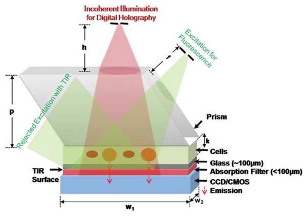
To address this important need for high-throughput fluorescent imaging, here we demonstrate a lens-free on-chip detection platform that can simultaneously record fluorescent images of labeled cells or other micro-objects over an ultra-wide FOV of 2.5 cm × 3.5 cm. In this lens-free imaging platform (Fig. 1), fluorescent micro-objects (e.g., within a microfluidic chip) are directly positioned onto a CCD or CMOS sensor array with less than ∼0.5–1.0 mm distance between the sample and sensor planes. To better control this vertical distance in our work, we used decapped sensors such that the protective coverglass of the chip was removed. The fluorescent cells/particles are then pumped at their proper excitation wavelength using e.g., a simple light emitting diode (LED) or a Xenon lamp (tuned to an appropriate spectrum by a monochromator) through the side facet of a prism as illustrated in Fig. 1. This incoherent excitation beam, after interacting with the sample volume, is reflected through a total internal reflection (TIR) process occurring at the bottom facet of the sample device. The fluorescent emission from the excited cells/particles, however, does not entirely obey TIR and therefore can be directly detected without the use of any lenses over the entire FOV of the sensor-array (2.5 cm × 3.5 cm). Quite importantly, the detection numerical aperture (NA) of this on-chip system is close to 1.0 since the large-area detector is placed very close to the fluorescent micro-objects, making it highly efficient for photon detection. In other words, only the oblique fluorescent rays that make up the numerical aperture between ∼1 and ∼1.3 (refractive index of the medium inside the channel) are lost without reaching the detector-array. Meanwhile, unlike a lens-based microscope, this large detection numerical aperture does not directly contribute to spatial resolution in our scheme due to its lensless operation.
Fig. 1.

On-chip platform for lens-free fluorescent imaging over a large FOV of 2.5 cm × 3.5 cm. Fluorescent excitation is achieved by using side illumination through a rhomboid prism (conveniently a different prism geometry could also be used). A simple LED or a Xenon lamp tuned by a monochromator is used for excitation. Lens-free holographic imaging14 of the same FOV is achieved through vertical incoherent illumination (another LED) which uses the flat top part of the prism. Drawing is not to scale. Dimensions: prism height, p (17 mm); imager active area, w1 × w2 (25 × 35 mm); depth of the solution reservoir, k (∼10–100 μm); distance of the vertical source, h (∼5–10 cm); distance of the fluorescent excitation source, f (∼1–2 cm). Not shown here, an index matching gel can also be used to avoid TIR and undesired scattering at the bottom facet of the prism. Note also that to better control the vertical distance between the sample micro-channel and the active region of the sensor, we removed the protective coverglass of the chip. The thin absorption filter shown above acts as a protective layer in this case, isolating the active region of the sensor chip from the micro-channels.
Another important feature of this platform is that since the TIR process is very powerful in rejection of the excitation source, a high-end thin-film interference based fluorescent filter is not needed in our case, and an inexpensive plastic-based absorption filter (with a cost of ∼0.6 USD per cm2) can be used, eliminating the need for expensive customized filters for each sensor size. This inexpensive absorption filter (placed between the sample and the sensor planes, with a thickness of e.g., <100 μm) is useful to reject the scattered pump photons that violate the TIR condition, and thus provides a better dark-field background.
In the configuration of Fig. 1, since no lenses are involved in imaging, the fluorescent emission of cells or particles will diverge rapidly, potentially overlapping with each other at the sensor plane. To combat this limitation, we use the measured incoherent point-spread function of our fluorescent detection platform to deconvolve the acquired lens-free images. This digital deconvolution process improves the resolving power of our platform by ∼5 fold, enabling a resolution of ∼40–50 μm over the entire sensor FOV i.e., 2.5 cm × 3.5 cm. For rare cell applications, spatial resolution is less of a concern since the statistical overlap of cells is unlikely. Therefore the limited spatial resolution of our lens-free fluorescent imaging platform should still be sufficient for use in rare cell analysis when combined with microfluidic chips. The lensless on-chip operation of our approach also provides compactness that can complement the miniaturized platform of microfluidics, while significantly improving the overall throughput of imaging.
To demonstrate the feasibility of our approach, we initially imaged a heterogeneous solution containing 10 μm diameter fluorescent particles (excitation/emission: 495/505 nm), and 20–30 μm diameter non-fluorescent particles as illustrated in Fig. 2 and Fig. 4. The sample was prepared by using a micropipette to drop 15–20 μl of this solution on a microscope slide placed under a rhomboid prism (base: 25 × 35 mm; height: 17 mm, Edmund Optics) as illustrated in Fig. 1. A long pass absorption filter (Kodak Wratten Color Filter 12, <30 dB for <500 nm; <0.1 mm thick, Edmund Optics) is also utilized on the surface of the charge coupled device (CCD, KAI-11002, Kodak). Excitation was achieved using a blue LED (470 nm peak, 30 nm bandwidth, Luxeon Star) pumped through the side facet of the prism (Fig. 1).
Fig. 2.

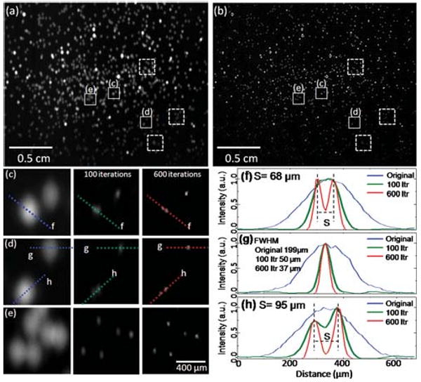
(a) Lens-free fluorescent imaging is illustrated over a FOV of >8 cm2 for 10μm fluorescent beads (excitation/emission: 495 nm/505 nm). The raw lens-free image (a) was pumped through an LED (see Fig. 1) and was acquired with an integration time of 1 s, (b) illustrates the digitally deconvolved fluorescent image of the same FOV. The zoomed images (c–e) are cropped from the raw fluorescent image (a), and next to each zoomed image, the result of the deconvolution process is illustrated as a function of the number of iterations (100 vs. 600). In (c) and (d), the letters and the dashed lines within the frames refer to (f) and (h), which illustrate different cross-sections of the raw and the deconvolved fluorescent images, demonstrating ∼5× improvement in fluorescent spot size. Through the iterative deconvolution process two particles that almost completely overlap at the raw lens-free image, see for instance (c–d), can now be separated from each other as shown to the right of (c–d) and in (f, h). Note that the pixel size of the CCD in this experiment is 9 μm, and the resolution of the deconvolved lens-free fluorescent image could be further improved with a smaller pixel.
Fig. 4.

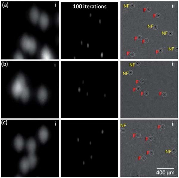
Lens-free holography14 and on-chip fluorescent imaging is demonstrated within regions shown with the dashed squares of Fig. 2(a–b). In (a–c) left column, the raw lens-free fluorescent images are shown. To the right of these images, the results of digital deconvolution are presented. In (ii) on the far right, lens-free holographic imaging results of the same field of view are presented, which show the shadow signatures of all the particles, both fluorescent (F) and non-fluorescent (NF), whereas the other images on the left only show the fluorescent signatures.
As illustrated in Fig. 2, with a vertical distance of ∼200 μm between the sample and the sensor planes, the size of each detected spot corresponding to a fluorescent particle was ∼200–300 μm, which resulted in significant overlap at the raw lens-free image (see Fig. 2(a)). Through digital deconvolution of the measured incoherent point-spread function of the lens-free system, we reconstructed a much higher resolution fluorescent image (Fig. 2(b)), which now exhibits ∼5× improved spatial resolution over the entire FOV of >8 cm2. This resolution improvement resulted in separation of significantly overlapping fluorescent particles from each other as highlighted in Fig. 2(c,d) and 2(f,h). In this deconvolution process, the raw lensless fluorescent image was iteratively refined by an accelerated Lucy–Richardson algorithm.6–8 By applying Bayes' theorem with the incoherent point-spread function of the on-chip system, the Lucy–Richardson algorithm updated the maximum-likelihood estimation of the fluorescence source distribution in each iteration.6,7 Prior to this calculation, we estimated the incoherent point-spread function of the system by averaging several measured patterns created by small isolated fluorescent beads. These patterns were aligned with respect to their center of mass coordinates and were individually normalized by their intensities before the averaging process. Since the pixel size of the image sensor is relatively much smaller than the width of the point spread function, the alignment errors due to pixelation or node mis-location within a single pixel can be neglected. Furthermore, since our on-chip fluorescent imaging approach does not utilize any lenses, the detection system was spatially invariant which means a single incoherent point spread function can be faithfully used for deconvolving the whole field-of-view.
This iterative deconvolution process was terminated (typically after a hundred cycles) before the emergence of noise amplification to ensure minimal square error between the projected and the measured profiles. The convergence of this algorithm was also accelerated by a vector extrapolation method to shorten the computation time.8 Coded in MATLAB 2009a, computation of 100 iterations for an image size of 4200 × 2700 pixels with an incoherent point spread function of 70 × 50 pixels takes around 10 min on a dual-core 1.8 GHz Pentium CPU. Since the deconvolution algorithm is highly parallel and iterative, the computation time can be reduced by >40× using a GPU (graphics processing unit – e.g., NVIDIA GeForce GTX 285) with a high performance pipeline structure.9–11
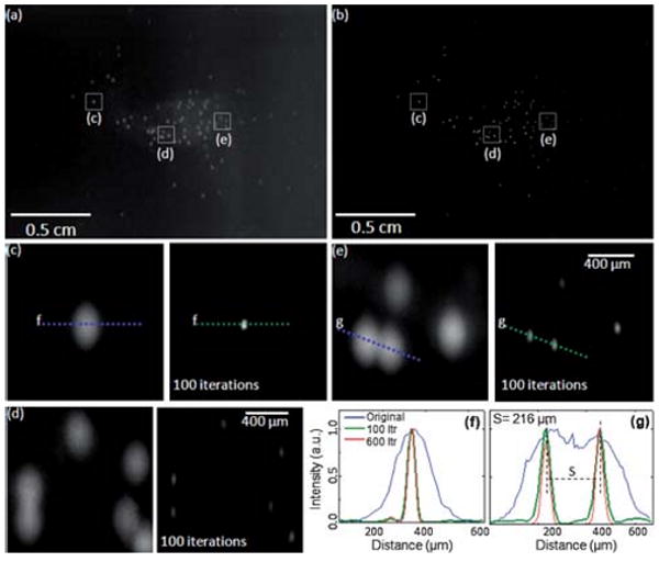
Next we imaged fluorescently labeled white blood cells (WBCs) in diluted whole blood samples. In these experiments, the cells were labeled by Calcein reagent (excitation 495 nm/emission 515 nm, LIVE Viability Assay, Moleculer Probes). To this end, 2–3 μl of whole blood is mixed with PBS (1 : 400 ratio) and 20 μm non-fluorescent microspheres (spacer to prevent cell rupture). Then 0.5 μl of 4 mM Calcein AM is added to the diluted blood, and incubated at room temperature for <20–30 min. Once green fluorescence in live cells is activated, the same experimental protocol is performed as reported for Fig. 2. Our results (see Fig. 3) indicate that the contrast of lens-free fluorescent imaging is sufficiently high even with labeled WBCs in whole blood samples. Note that in this experiment, platelets were also labeled which contributed to an increased background fluorescence. Despite this increased noise, our deconvolution algorithm still performed very well yielding a similar reconstruction performance as also quantified in Fig. 3(f–g). In a rare cell experiment, however, such an increase in the background fluorescence would not be present since surface chemistry steps followed by washing of the micro-channel would normally eliminate most of the undesired background fluorescence within the imaging FOV. Non-specific binding in such an experiment still remains an issue to be addressed by appropriate surface chemistry protocols,12 which are not the focus of this manuscript.
Fig. 3.

Lens-free fluorescent imaging (a) and the results of the iterative deconvolution algorithm (b) are demonstrated for Calcein Labeled WBCs. The zoomed images at the bottom are cropped from (a) and (b) to illustrate the success of the deconvolution. (f) and (g) illustrate the cross-sections of fluorescent signatures for the raw lens-free image (blue curve) as well as for 100 (green curve) and 600 (red curve) iterations of deconvolution. The FWHM of the deconvolved fluorescent signature in (f) improved by ∼5× from 191μm to 38μm. (g) illustrates a similar situation for two overlapping fluorescent signatures.
Note that the same TIR prism interface of Fig. 1 also permits lens-free holography13,14 to be performed for transmission imaging of the same sample volume. By using an incoherent source (such as an LED) that illuminates the sample from the top (Fig. 1), lens-free holographic shadows14 of the cells/particles can also be imaged on the same chip to create a dual imaging platform. Fig. 4 illustrates the performance of this dual imaging capability, where the raw lens-free fluorescent images and their deconvolution results are compared against the vertical transmission images of the same sample volume using lens-free holographic imaging as shown in Fig. 1. This imaged sample contained (on purpose) some fluorescent particles as well as some non-fluorescent ones. Therefore, the transmission holographic images contained the shadow signatures of all the particles, whereas only the fluorescent ones appeared in the lens-free fluorescent images as illustrated in Fig. 4, validating the concept dual imaging on the same lensless platform. Such a dual-imaging capability would be quite useful especially to increase the specificity and the functionality of lens-free on-chip imaging.
In our technique, the use of TIR to block the excitation beam is quite efficient for rejection of high pump powers and it works independent of the excitation and emission wavelengths. This TIR interface is also quite useful since it avoids the use of thin-film based fluorescent filters, which are wavelength and illumination direction dependent making them inconvenient and costly to customize for lens-free operation. Note that in the reported results (Fig. 2–4), besides TIR, an inexpensive plastic-based absorption filter (less than 5 USD for >8 cm2 area) is also used to filter out the weakly scattered excitation light that does not obey TIR. The requirements on this filter's performance are greatly reduced due to TIR's efficiency in rejecting the excitation beam.
Finally, we would like to point out that the lens-free fluorescent imaging configuration illustrated in Fig. 1 should not be confused with existing TIR fluorescence (TIRF) microscopes.15–17 There are several important differences between the two. Conventional TIRF systems are not lens-free as they often utilize high NA objective lenses as part of a conventional microscope. More importantly, in TIRF configuration, the excitation is achieved through evanescent waves that can only cover a very thin sample volume (<100 nm deep). However, in our technique, the sample excitation occurs through travelling waves, i.e., the entire sample volume (with depths ranging from a few microns to hundreds of microns) can be easily excited. In this sense, our platform is a microscopic imager that is targeted towards lens-free fluorescent imaging of particles and cells on a chip, whereas TIRF microscopy is suited for imaging molecular level interactions over very thin volumes.
Acknowledgments
We acknowledge the support of the Okawa Foundation, Vodafone Americas Foundation, DARPA DSO (under 56556-MS-DRP), NSF (under Awards # 0754880 and 0930501), NIH (under 1R21EB009222-01 and the NIH Director's New Innovator Award – Award Number DP2OD006427 from the Office Of The Director, National Institutes Of Health), AFOSR (under Project # 08NE255) and ONR (under Young Investigator Award 2009).
References
- 1.Shaner NC, Steinbach PA, Tsien RY. Nat Methods. 2005;2(12):905. doi: 10.1038/nmeth819. [DOI] [PubMed] [Google Scholar]
- 2.Lichtman JW, Conchello JA. Nat Methods. 2005;2(12):910. doi: 10.1038/nmeth817. [DOI] [PubMed] [Google Scholar]
- 3.Fu AY, Spence C, Scherer A, Arnold FH, Quake SR. Nat Biotechnol. 1999;17:1109–1111. doi: 10.1038/15095. [DOI] [PubMed] [Google Scholar]
- 4.Nagrath S, Sequist LV, Maheswaran S, Bell DW, Irimia D, Ulkus L, Smith MR, Kwak EL, Digumarthy S, Muzikansky A, Ryan P, Balis UJ, Tompkins RG, Haber DA, Toner M. Nature. 2007;450:1235–1239. doi: 10.1038/nature06385. [DOI] [PMC free article] [PubMed] [Google Scholar]
- 5.Krivacic RT, Ladanyi A, Curry DN, Hsieh HB, Kuhn P, Bergsrud DE, Kepros JF, Barbera T, Ho MY, Chen LB, Lerner RA, Bruce RH. Proc Natl Acad Sci U S A. 2004;101(29):10501–10504. doi: 10.1073/pnas.0404036101. [DOI] [PMC free article] [PubMed] [Google Scholar]
- 6.Richardson WH. J Opt Soc Am. 1972;62:55–59. [Google Scholar]
- 7.Lucy LB. Astron J. 1974;79:745–754. [Google Scholar]
- 8.Biggs DSC, Andrews M. Appl Opt. 1997;36:1766–1775. doi: 10.1364/ao.36.001766. [DOI] [PubMed] [Google Scholar]
- 9.Manavski S, Valle G. BMC Bioinformatics. 2008;9:S10. doi: 10.1186/1471-2105-9-S2-S10. [DOI] [PMC free article] [PubMed] [Google Scholar]
- 10.Fung J, Mann S. 2008 IEEE International Conference on Multimedia and Expo; June 23–April 26 2008.pp. 9–12. [Google Scholar]
- 11.Domanski L, Vallotton P, Wang D. 18th World IMACS/MODSIM Congress; Cairns, Australia. 13–17 July 2009. [Google Scholar]
- 12.Murthy SK, Sin A, Tompkins RG, Toner M. Langmuir. 2004;20:11649–11655. doi: 10.1021/la048047b. [DOI] [PubMed] [Google Scholar]
- 13.Su TW, Seo S, Erlinger A, Ozcan A. Biotechnol Bioeng. 2008;3:102. doi: 10.1002/bit.22116. [DOI] [PMC free article] [PubMed] [Google Scholar]
- 14.Seo S, Su TW, Tseng DK, Erlinger A, Ozcan A. Lab Chip. 2009;9:777–787. doi: 10.1039/b813943a. [DOI] [PMC free article] [PubMed] [Google Scholar]
- 15.Axelrod D. Traffic. 2001;2:764–774. doi: 10.1034/j.1600-0854.2001.21104.x. [DOI] [PubMed] [Google Scholar]
- 16.Schneckenburger H. Curr Opin Biotechnol. 2005;16:13–18. doi: 10.1016/j.copbio.2004.12.004. [DOI] [PubMed] [Google Scholar]
- 17.Roy SR, Hohng S, Ha T. Nat Methods. 2008;5:507–516. doi: 10.1038/nmeth.1208. [DOI] [PMC free article] [PubMed] [Google Scholar]


