Abstract
Purpose
To study temperature and thermal dose distributions of ThermoBrachytherapy Surface Applicators (TBSA) developed for concurrent or sequential high dose rate (HDR) brachytherapy and microwave hyperthermia treatment of chest wall recurrence and other superficial disease.
Methods
A steady state thermodynamics model coupled with the fluid dynamics of water bolus and electromagnetic radiation of hyperthermia applicator is used to characterize the temperature distributions achievable with TBSA applicators in an elliptical phantom model of the human torso. Power deposited by 915 MHz conformal microwave array (CMA) applicators is used to assess the specific absorption rate (SAR) distributions of rectangular (500 cm2) and L-shaped (875 cm2) TBSA. The SAR distribution in tissue and fluid flow distribution inside the Dual-Input Dual-Output (DIDO) water bolus are coupled to solve the steady state temperature and thermal dose distributions of rectangular TBSA (R-TBSA) for superficial tumor targets extending 10–15 mm beneath the skin surface. Thermal simulations are carried out for a range of bolus inlet temperature (Tb=38–43°C), water flow rate (Qb=2–4 L/min) and tumor blood perfusion (ωb=2–5 kg/m3/s) to characterize their influence on thermal dosimetry.
Results
Steady state SAR patterns of R- and L-TBSA demonstrate the ability to produce conformal and localized power deposition inside tumor target sparing surrounding normal tissues and nearby critical organs. Acceptably low variation in tissue surface cooling and surface temperature homogeneity was observed for the new DIDO bolus at 2 L/min water flow rate. Temperature depth profiles and thermal dose volume histograms indicate bolus inlet temperature (Tb) to be the most influential factor on thermal dosimetry. A 42 °C water bolus was observed to be the optimal choice for superficial tumors extending 10–15 mm from the surface even under significant blood perfusion. Lower bolus temperature may be chosen to reduce thermal enhancement ratio (TER) in the most sensitive skin where maximum radiation dose is delivered and to extend thermal enhancement of radiation dose deeper.
Conclusion
This computational study indicates that well-localized elevation of tumor target temperature to 40–44 °C can be accomplished by large surface-conforming TBSA applicators using appropriate selection of coupling bolus temperature.
Keywords: chestwall recurrence, conformal thermal therapy, hyperthermia, brachytherapy, thermoradiotherapy, specific absorption rate, thermal dose
Introduction
Numerous preclinical data and Phase I/II clinical trials have demonstrated the effectiveness of hyperthermia as a radiation sensitizer and inhibitor of radiation damage repair. Similar effects of heat have been reported for tumors exposed to radiation (Sneed et al., 2004; Seegenschmiedt et al., 1995, 1996) which has motivated the development of hyperthermia devices capable of delivering localized heat to tumor targets in order to spare adjacent normal tissues and critical organs (Stauffer, 2005). Localized hyperthermia at moderate temperatures (40–45 °C) delivered as an adjuvant for radiation and chemotherapy has been reported to improve local control and survival rate for various tumors (Jones et al., 2005; Jones et al., 2003; Perez et al., 1991; Sherar et al., 1997; Sneed et al., 2004; Sneed et al., 1998; van der Zee et al., 2000; Vernon, 1994; Vernon et al., 1996). Furthermore, preclinical work has shown that reducing the time interval between radiation and heat treatments increases the TER of thermoradiotherapy from 1.5 for sequential treatments to 2.5 or higher when heat and radiation are applied simultaneously (Overgaard, 1980). Early clinical results that used linear accelerator and cobalt-60 radiation with commercial hyperthermia applicator demonstrated the feasibility of concurrent thermoradiotherapy (Moros et al., 1995b; Myerson et al., 1999). Encouraging preliminary results led to the development of combination applicators such as the scanning ultrasound reflector linear array system (SURLAS) (Moros et al., 1995a; Novak et al., 2005; Novak et al., 2008) and the conformal thermobrachytherapy applicator of this study (Juang et al., 2006; Stauffer et al., 2004; Stauffer et al., 2005; Taschereau et al., 2004). Over the years, we improved the design of the TBSA to combine HDR brachytherapy and heat using 915 MHz Conformal Microwave Array (CMA) applicators. The TBSA is designed for thermoradiotherapy of diffuse chestwall recurrence which typically extends from the skin to a depth of 10–15 mm (Arunachalam et al., 2009a; Craciunescu et al., 2009). The TBSA reported in this work employs a recently optimized water bolus design with Dual-Input and Dual-Output (DIDO) flow channels that produce a more uniform flow distribution across the large target surface (Arunachalam et al., 2009b). Initial testing of the TBSA applicator has demonstrated excellent conformity, nearly uniform flow distribution and, minimal attenuation of the HDR radiation source through water bolus and CMA applicator.
In this paper, a comprehensive steady state thermal analysis of the TBSA is presented by combining power deposition (or Specific Absorption Rate - SAR) from the CMA with the flow distribution inside the DIDO water bolus. The ability of TBSA to deliver localized power deposition inside large contoured superficial tumor targets is evaluated for varying size applicators. Thermal simulations are carried out for varying bolus inlet temperature (Tb), bolus flow rate (Qb) and tumor blood perfusion (ωb) to determine the factors influencing the heating pattern and thermal dose distribution of the TBSA. Finally, suggestions are provided to select appropriate bolus temperature and flow rate for the TBSA during thermobrachytherapy treatment, depending on the depth of the target disease from the skin surface.
Methods
TBSA
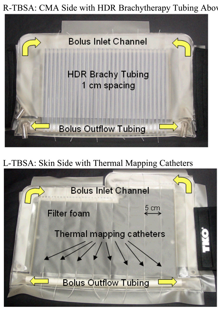
Fig 1 shows the rectangular (500 cm2) and L-shaped (875 cm2) TBSA applicators made of layers of 304.8 µm (12 mil) thick medical grade PVC film. The front skin contacting layer is the water bolus with DIDO flow channels and open cell filter foam which provides a relatively constant thickness coupling medium for microwaves emitting from the flexible printed circuit applicator. The water bolus also provides cooling of the high SAR on the target surface. The thickness of the waterbolus for the 915 MHz CMA is set to vary between 5–10 mm to avoid SAR perturbations arising due to resonance inside the bolus (Neuman et al., 2002; Rossetto and Stauffer, 1999). Similar observations were also reported for the 433 MHz contact flexible microstrip applicators (CFMA) used for superficial hyperthermia of chest wall recurrence and melanoma (Lee et al., 2004; Kok et al., 2009; Gelvich and Mazokhin, 2000). PVC thermal mapping catheters RF welded to the skin-contacting side of the water bolus enable surface temperature monitoring for feedback power control during hyperthermia treatment. A high density conformal thermal monitoring sheet (TMS) sensor array with fiberoptic sensors embedded between two flexible and thermally conducting polyimide films reported in (Arunachalam et al., 2008) can also be used with TBSA for real-time skin temperature monitoring and feedback power control. The fixed-geometry, body-conforming array of thermal sensors enables fast and accurate characterization of two-dimensional temperature distributions over large surface areas during hyperthermia treatment. The layer behind the waterbolus consists of the CMA heating device, an array of square dual concentric conductor (DCC) multi-fed radiating slots on a thin flexible printed circuit board using Rogers ULTRALAM® 3000 LCP laminates (Maccarini et al., 2009; Maccarini et al., 2005; Rossetto et al., 1998; Stauffer et al., 1995). The third layer is an array of parallel medical grade brachytherapy catheter tubes RF welded 10 mm apart on the PVC film. The PVC sheet holding the array of brachytherapy tubes is welded along three sides to the waterbolus to fix the alignment of brachytherapy tubes with waterbolus and DCC antenna array. 5F catheters are then used in each desired brachytherapy tube and connected via specialized clamping adapters to a remote aftreloader. During brachytherapy, the HDR radiation source is pulled incrementally at preplanned dwell times to paint the appropriate radiation pattern in tissue under the applicator. Elastic (Neoprene ®) flaps with Velcro fasteners are sewn to each side of the applicator to provide a tight conformal fit around the patient torso. An overlying vest with removable PVC air bladder forms an optional fourth layer that is used to improve applicator fit to convex areas such as over the sternum adjacent to a large breast. The vest is constructed of Neoprene® to secure the TBSA in place with respect to skin markers on the target surface. PVC luer lock hubs at all catheter tips are used to lock the thermal mapping probes. The conformal TBSA shown in Fig 1 was developed for chest wall recurrences in collaboration with Bionix Development Corporation (Paoli, PA).
Fig 1.
Rectangular and L-shaped TBSA made of medical grade PVC films. The applicator consists of a dual-input dual-output water bolus with open cell filter foam, thermal mapping catheters on skin contacting side for feedback control and an array of PVC tubing for HDR brachytherapy. The 915 MHz heating array (CMA) is placed between the bolus and brachytherapy tubing array. Elastic attachment with Velcro strap is used to support the TBSA securely to the patient torso. A stretchable vest is used to restrict TBSA movement with respect to the target.
Computational Model
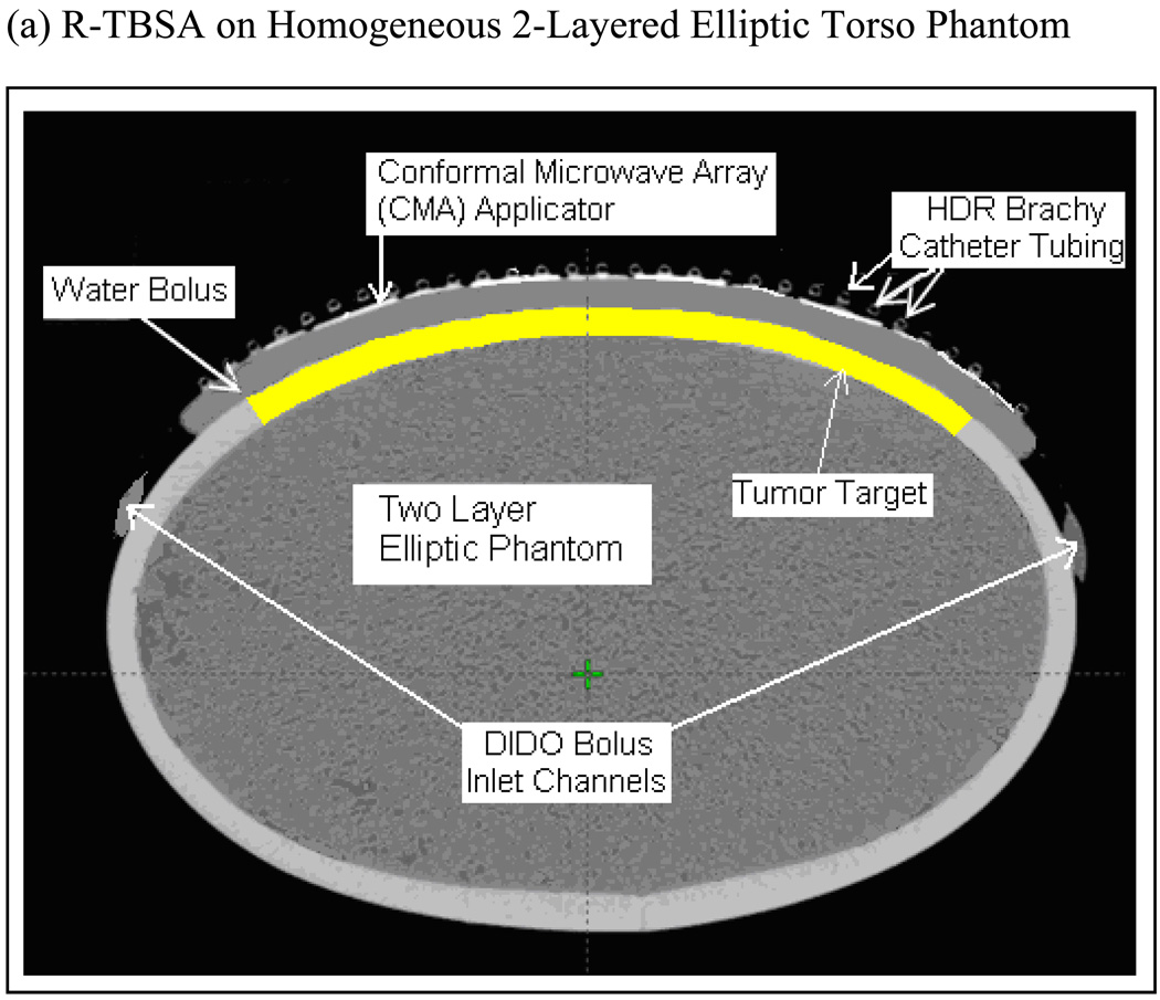
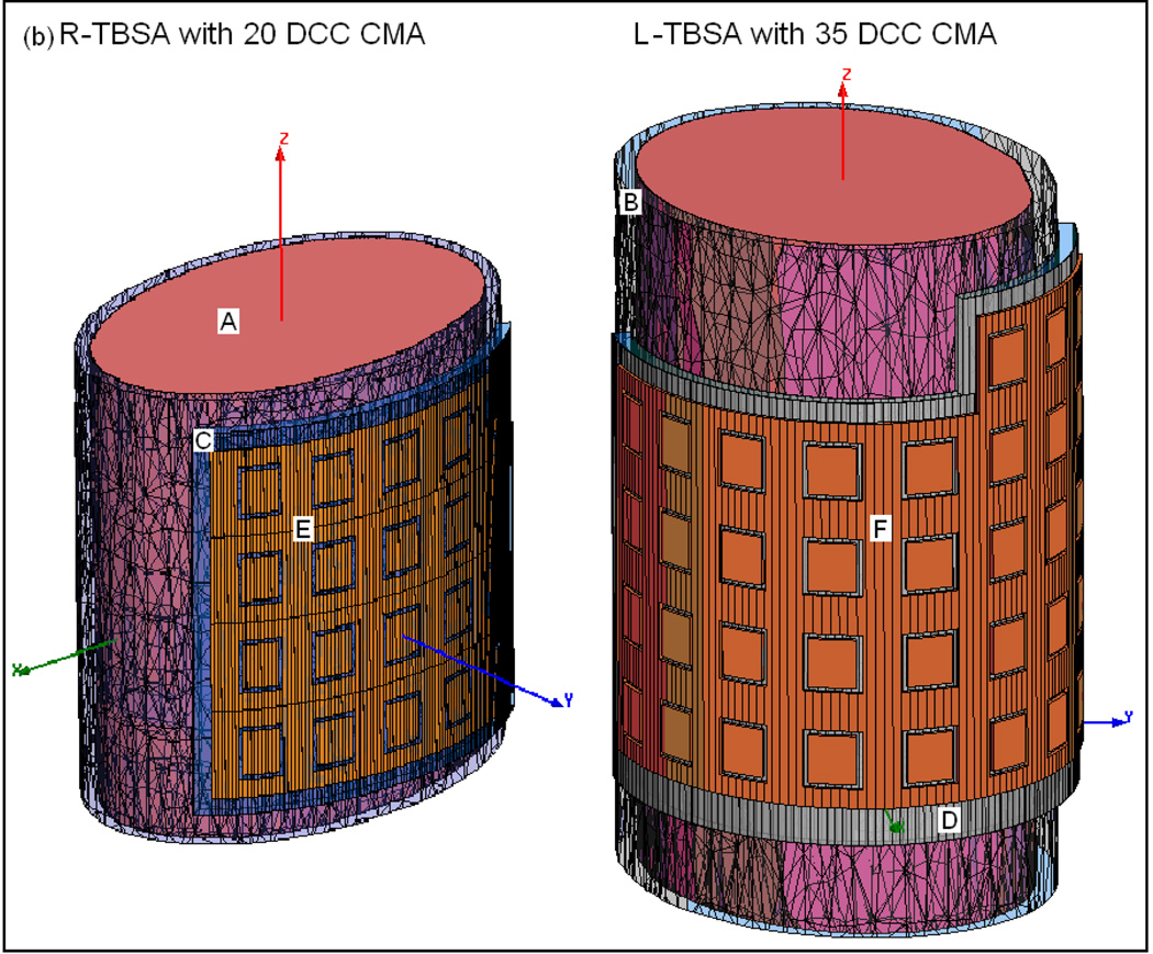
SAR and thermal simulations were carried out for an elliptical torso phantom model that was used in the dosimetric characterization of TBSA (Craciunescu et al., 2009). Fig 2a shows the cross sectional Computed Tomography (CT) image of R-TBSA on the phantom with a 5×4 DCC array between the 1 cm water bolus and HDR brachytherapy catheter array. The highlighted region in Fig 2a underneath the DIDO water bolus indicates the 10 mm deep tumor target considered in the theoretical model. Superficial chestwall disease that we treat typically extends 5–15 mm below the surface including the skin. Thus, the depths of the predefined tumor target volumes studied in our work extend 10–20 mm from the surface. CT images acquired every 3 mm along the long axis of the phantom were segmented using Avizo 6.2 (Visualization Science Group, Inc. Burlington MA) and imported into the simulation software. Fig 2b shows the 3D computational models of TBSA.
Fig 2.
TBSA on two-layered homogeneous elliptical torso phantom used in the simulations. (a) CT image of R-TBSA on elliptic phantom with the 5×4 DCC heating array between the bolus and brachytherapy catheter tubes (b) 3D models generated using CT images of TBSA on elliptic phantom; A- deep tissue, B – superficial tissue, C – bolus of water, D – PVC water bolus bag, E – 5×4 DCC array of R-TBSA, F – 35 element DCC array of L-TBSA.
CMA SAR Calculation
A coupled numerical model is developed to incorporate the SAR pattern of CMA and bolus fluid flow distribution in the thermal simulations. The electromagnetic (EM) field maintained by the CMA is calculated by solving Maxwell’s wave equation (Cheng, 1989),
| (1) |
using finite element EM simulation software, HFSS 12 (Ansoft/Ansys Inc, Philadelphia PA). In Eqn (1), E⃗ is electric field vector, r⃗ is 3D position vector inside the computational domain, f is operating frequency (f =915 MHz), ω is angular frequency, εo and μo are free space dielectric permittivity and magnetic permeability respectively and, εr is dielectric constant at f =915 MHz which is modeled to be homogeneous within each medium. The square slot DCC radiators of the CMA are excited by defining four dipole sources (1 W each) between the outer ground plane and central square patch conductor of the DCC across the center point of each side. The SAR distribution of the CMA array is obtained by linear superposition of power deposition patterns from all individual DCC antennas under incoherent excitation. The computational overhead is reduced by truncating the domain with perfectly matched layer (PML) absorbing boundary conditions (Berenger, 1994). The SAR,
| (2) |
calculated for individual DCC elements is superimposed to compute the power deposited by the complete array. In Eqn (2), σ and ρ are material conductivity at f = 915 MHz and density respectively inside the computational domain and are modeled as constants within each medium.
Bolus Fluid Dynamics
Steady state fluid flow distribution inside DIDO water bolus is calculated by solving Navier Stokes equation for incompressible fluid flow given by (Zienkiewicz et al., 2005),
| (3a) |
| (3b) |
inside the flow channels and, Brinkman’s equation for fluid flow inside the porous filter foam (Bars and Worster, 2006),
| (4) |
where u⃗ is spatial velocity vector, p is pressure distribution, η is water dynamic viscosity and, εp and kp are porosity and fluid permeability constants of the bolus filter foam. The total volume of fluid flowing through the DIDO water bolus is the sum of the flow from both input channels (Qb). The spatial distribution of water velocity (u⃗ = u⃗in) entering the active bolus area through the DIDO inlet flow channel calculated in (Arunachalam et al., 2009b) is used in the simulations. Laminar outflow is defined on the surface normal to the outlet side of the porous filter foam (Arunachalam et al., 2009b). A rigid wall boundary condition (u⃗ = 0) is applied on the walls of the PVC bolus. Fluid dynamics of the DIDO waterbolus were studied in detail and validated with experimental data in (Arunachalam et al., 2009b). The DIDO waterbolus maintained a nearly uniform fluid flow distribution across the large r-TBSA with less than 0.8°C gradient in the steady state bolus surface temperature (Arunachalam et al., 2009b).
Thermodynamics Equilibrium
Spatial distributions of fluid flow velocity (u⃗) and calculated SAR are used in the thermal simulations. Steady temperature inside the water bolus is modeled as,
| (5) |
where T is temperature field, kt is material thermal conductivity and c is specific heat capacity. Thermal properties are defined as constants within each medium. Equation (5) is solved inside the PVC bolus layers for u⃗ = 0. Convective heat transfer on the boundary surface between the applicator and surrounding room temperature air is modeled by the boundary condition, ktn̂·∇T = ha(T − Tr) where ha and Tr are heat convection coefficient and ambient room temperature respectively and, n̂ is surface normal vector of the boundary. The temperature of the water entering the bolus is set to a constant, T=Tb. Heat transfer inside the tumor target and surrounding tissue is modeled using Pennes bio heat equation (Wissler, 1998),
| (6) |
where Ta is arterial blood temperature (set to 37°C), QEM = ρSAR is EM power deposited inside tumor and tissue and, ωb and cb are bulk perfusion rate and specific heat capacity of blood respectively. The first term in Eqn (6) models conductive heat transfer inside tissue, the second term models bulk heat loss inside tissue due to blood flow. The computational domain for thermal analysis is truncated by defining the temperature field to T=Tc, 4 cm deep inside elliptic phantom model wher, Tc is body core temperature set to 37 °C. A 304.8 µm thick PVC water bolus with 10 mm degassed and de-ionized water inside open cell filter foam is used in the simulations. A list of material properties used in the simulations is summarized in Table 1. Fluid dynamics and thermal simulations were carried out using the finite element software, Comsol (Comsol Inc. Stockholm Sweden). The simulation tools used in this study were validated in our previous works (Arunachalam et al., 2009b; Birkelund et al., 2009; Arunachalam et al., 2008).
Table 1.
Material properties used in the simulations.
| Material | Electrical Conductivity, σ [S/m] |
Dielectric Constant, εr |
Density, ρ [kg/m3] |
Thermal Conductivity, kt [W/m/K] |
Specific Heat Capacity, c [J/kg/K] |
|---|---|---|---|---|---|
| Deionized Water | 0.17 | 78 | 1000 | 0.61 | 4200 |
| Muscle | 0.95 | 54.99 | 1000 | 0.56 | 2800 |
| PVC | 2E-4 | 3.5 | 1300 | 0.16 | 1500 |
Specific heat capacity of blood, cb = 3825 [J/kg/K]
Ambient room temperature, Tr = 21°C
Heat transfer coefficient at Tr, ha=13.5 [W/m2/K]
Water dynamic viscosity, η=6.3e-4 kg/m/s
Filter foam porosity, εp =3.3e-7 and permeability, kp =0.85 m2.
Simulations
SAR Characterization
EM simulations were carried out for the TBSA applicators depicted in Fig 1. A 5×4 DCC array (500 cm2) is used with the R-TBSA and a 35-element L-shaped DCC array (875 cm2) is used with the L-TBSA. SAR distributions were calculated inside the tissue including predefined tumor target volume (highlighted in Fig 2a). As heat radio-sensitizes both normal and tumor tissues, it is crucial to selectively deposit EM power within the target disease sparing the surrounding normal tissues. Unlike deep tissue heating, in hyperthermia treatment of superficial disease such as chestwall recurrence, the entire tissue region up to 10–15 mm depth beneath the DCC heating array is considered tumor target. Hence, thermal enhancement is readily limited to the tumor target and irregularly shaped disease regions can be treated using a multi-element heating array by selectively switching ON DCC antennas over the target tissue. Additional simulations were carried out by switching off several DCCs in the 5×4 DCC array to evaluate the ability to deliver well-localized conformal power deposition patterns to irregular shaped target lesions.
Thermal Characterization
Steady state thermal simulations were carried out for the R-TBSA using the calculated power deposition pattern for all heating elements of the 5×4 DCC array. Thermal characteristics of R-TBSA were studied for the following parameters: water bolus inlet temperature, Tb (38–43 °C); bolus flow rate, Qb (2–4 L/min) and blood perfusion rate inside tumor target, ωb (2–5 kg/m3/s). Due to the superficial extent of tumor target, lower limit on Tb is set to 38°C which is slightly above normal skin surface temperature (35–36°C) and, the upper limit is set to 43°C to limit thermal enhancement of radiation dose to the skin. Blood perfusion rate (ωb) that contributes to heat loss in Pennes Bio-heat equation (6) is varied from 2–5 kg/m3/s inside tumor target to bracket the range of values that can be anticipated during hyperthermia treatment. Three blood perfusion rates – moderate (ωb=2), intermediate (ωb=3.5) and very high (ωb=5) – are used in the simulations based on the expected range under hyperthermic conditions (Roemer, 1990; Van De Kamer et al., 2001). Heat convection effect of the DIDO waterbolus is evaluated in this study at 2 and 4 L/min flow rates to determine the minimum flow capacity of the bolus circulation system. The lower limit (2 L/min) is established based on the capabilities of the water circulation system used in our clinic. A practical upper limit of 4 L/min is set to minimize turbulence and weakening of the PVC bolus with time.
A total of 36 thermal simulations were carried out for the R-TBSA. In all our thermal simulations, steady state temperatures of 40–44 °C are defined as the therapeutic temperature range for superficial hyperthermia. Heat input from the CMA (QEM) in Eqn (6) was scaled for individual simulations such that the maximum temperature inside the predefined tumor target is limited to 44°C. Heat convection inside the circulating waterbolus was demonstrated to impact tissue surface cooling and temperature homogeneity of the 915 MHz CMA array (Birkelund et al., 2009). As a result, a new bolus configuration with DIDO flow channels was developed for use with our large area TBSA (Arunachalam et al., 2009b). Additional simulations were carried out in this study to assess heat convection effects of DIDO bolus on surface temperature distributions at 2 and 4 L/min water flow rates for R-TBSA with 42 °C bolus and power deposition from 16 of the 20 DCC elements. Steady state temperature distributions were used to compute T90 (temperature that 90% of the target volume is above) and CEM43T90 (cumulative equivalent minutes assuming constant 43 °C delivered to 90% of the tumor target) (Dewey, 1994) for varying bolus temperature and tumor volumes under moderate and very high blood perfusion – the possible scenarios anticipated during hyperthermia treatment. Simulation results are used to determine factors influencing the thermal characteristics of TBSA.
Results
SAR Pattern
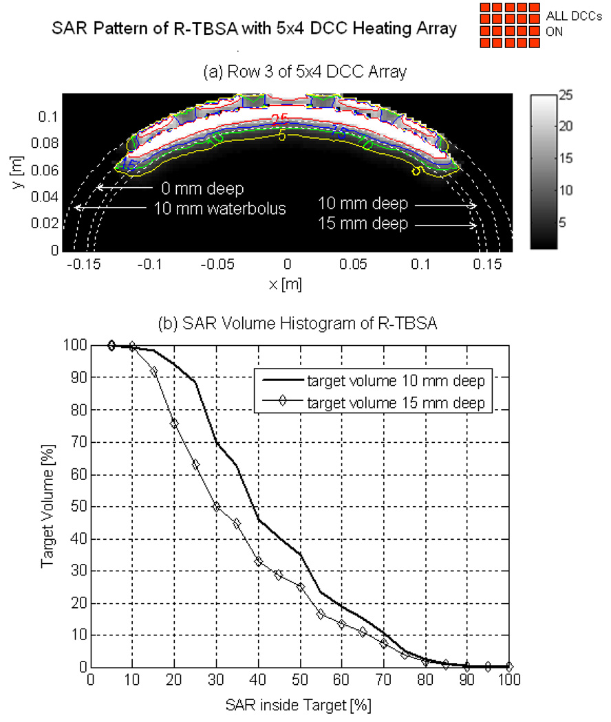
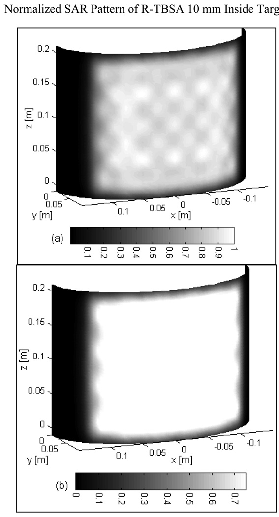
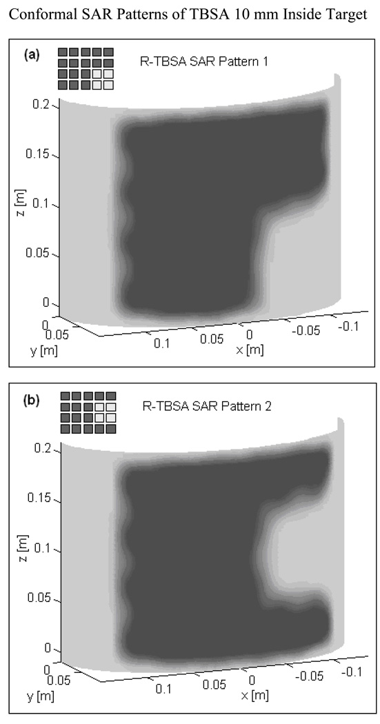
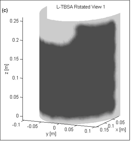
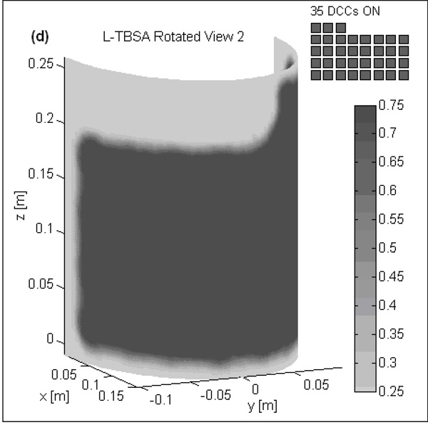
Fig 3 shows the normalized SAR pattern delivered by the 5×4 DCC array of R-TBSA. SAR depth distribution of Fig 3a is calculated in the mid plane of the last row of the 5×4 heating array normalized with respect to the maximum value inside the computational domain. Similar SAR distributions were observed across the remaining rows of the DCC array with maximum SAR deposited on the target surface. Due to low electrical conductivity, minimal power is absorbed inside the de-ionized water bolus. Fig 3b shows the corresponding SAR volume histogram calculated inside the predefined tumor target volumes of the torso phantom model for the 5×4 DCC array of the R-TBSA. SAR volume histograms indicate that 90% of the tumor target received at least 15% of the maximum power deposition. Fig 4 shows the 3D SAR distribution on the elliptic phantom shell, 10 mm from the target surface. The SAR pattern of Fig 4a is normalized with respect to the maximum SAR value at depth (SARmax). The thresholded SAR distribution of Fig 4b indicates that 90% of the tumor target is above 75% of SARmax. Fig 5 shows the normalized 3D SAR patterns of R-TBSA and L-TBSA for tumor targets of varying size and shapes. Well-localized power deposition inside the tumor target seen in Fig 3–Fig 5 facilitates selective radio-sensitization of superficial tumors, sparing surrounding normal tissues and limiting TER enhancement to the predefined tumor target volume during simultaneous thermobrachytherapy.
Fig 3.
SAR distribution maintained by the 5×4 DCC array of R-TBSA inside elliptic phantom model. (a) 2D SAR distribution across the mid plane of the last row of 5×4 DCC array normalized with respect to the maximum value inside the computational domain. (b) SAR volume histogram inside superficial tumors extending 10 and 15 mm deep from target surface.
Fig 4.
(a) 3D SAR distribution of R-TBSA inside tumor target normalized with respect to the maximum value at depth (10 mm) (b) SAR pattern of Fig 4a thresholded to show target above 75% of the maximum SAR value of the 5×4 DCC array.
Fig 5.
SAR distribution at depth inside tumor target maintained by CMA applicators of varying size (500–875 cm2) 10 mm from target surface. Adjustable and localized heat patterns inside the tumor target under the R-TBSA in Fig 5a–b and L-TBSA in Fig 5c–d should facilitate selective radio-sensitization of a tumor target, sparing surrounding critical normal tissues.
Effect of Bolus Temperature and Perfusion on Target Temperature Distribution
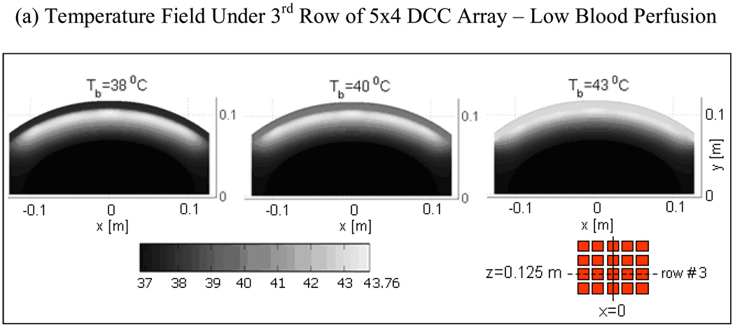
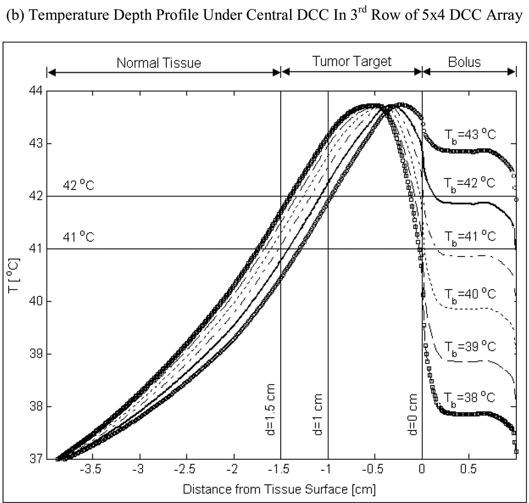
Fig 6 shows the depth profiles and 2D distribution of steady state temperature field for a range of bolus inlet temperature (Tb=38–43°C) with moderate blood perfusion (ωb=2 kg/m3/s) inside tumor target. Temperature distributions of Fig 6a were taken in the mid plane of the 3rd row of the 5×4 DCC array (z=12.5 cm). The temperature distributions in Fig 6a indicate that therapeutic thermal elevation (40–44°C) inside the tumor target can be moved deeper by lowering bolus temperature. The corresponding temperature depth profiles in Fig 6b at x=0 and z=12.5 cm clearly illustrate this phenomenon. Lowering the bolus temperature from 43 to 38°C broadens the temperature field and moves peak tissue temperature 3–4 mm deeper into the tumor target. From Fig 6, it can be observed that superficial tumors extending 10–15 mm from the skin including skin can be effectively treated with 41–43°C waterbolus temperature while tumors extending as deep as 15–20 mm or requiring protection from skin complications can be treated using 39–40°C water bolus.
Fig 6.
Steady state temperature distributions produced by 5×4 DCC CMA of R-TBSA for varying bolus temperature and moderately perfused tumor target (ωb=2 kg/m3/s) at 4 L/min bolus flow rate. (a) 2D temperature fields beneath the 3rd row of 5×4 DCC CMA at z=0.125m; (b) Temperature depth profiles at x=0 and z=0.125 m indicating the impact of bolus temperature on tissue heating.
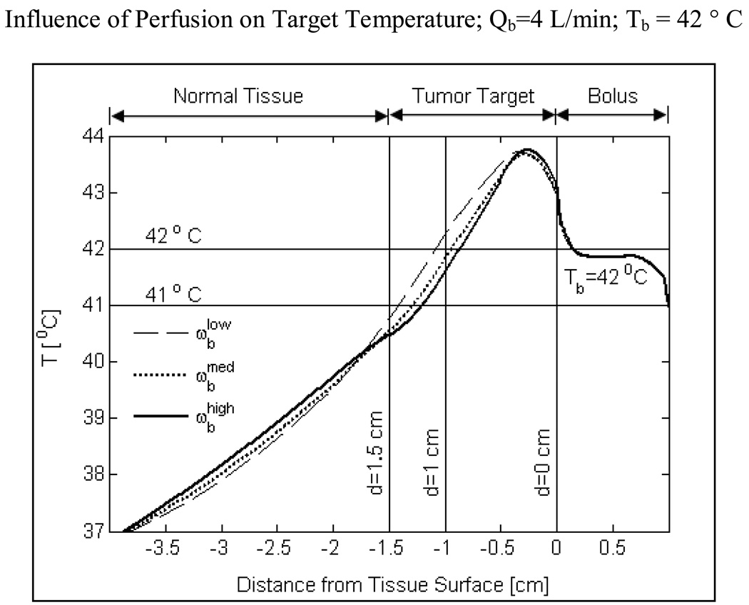
Fig 7 shows the influence of tumor blood perfusion on target temperature for a 42°C bolus. In these simulations, muscle tissue surrounding the tumor target is maintained at a moderate perfusion rate of 2 kg/m3/s which is well above that of resting muscle (0.5–1.5 kg/m3/s). Increasing blood perfusion causes an imbalance between heat input from the CMA and heat lost due to blood flow inside the tumor target. Further, as the SAR decays with depth, heat lost due to increasing tumor blood perfusion becomes more pronounced at depth as shown in Fig 7. Despite the heat loss with increasing perfusion, Fig 7 demonstrates that it is possible to elevate tumor temperatures into the therapeutic range (40–44°C) for superficial disease extending 10–15 mm from the surface using a 42°C water bolus. Temperatures below the therapeutic range were observed at lower bolus temperatures and very high blood perfusion inside the tumor target (simulation data not shown).
Fig 7.
Temperature depth profiles maintained by the 5×4 DCC array of R-TBSA for a range of bulk blood perfusion rate that bracket moderate to severe perfusion inside the tumor target. Normal tissues surrounding the tumor target were maintained at moderate perfusion (2 kg/m3/s) in all simulations. Thermal simulations were carried out for a 42 °C water bolus and 4 L/min bolus flow rate. The ability to heat deeper inside the tumor target is limited by tumor perfusion.
Convection Effect of Water Bolus on Surface Cooling and Temperature Homogeneity
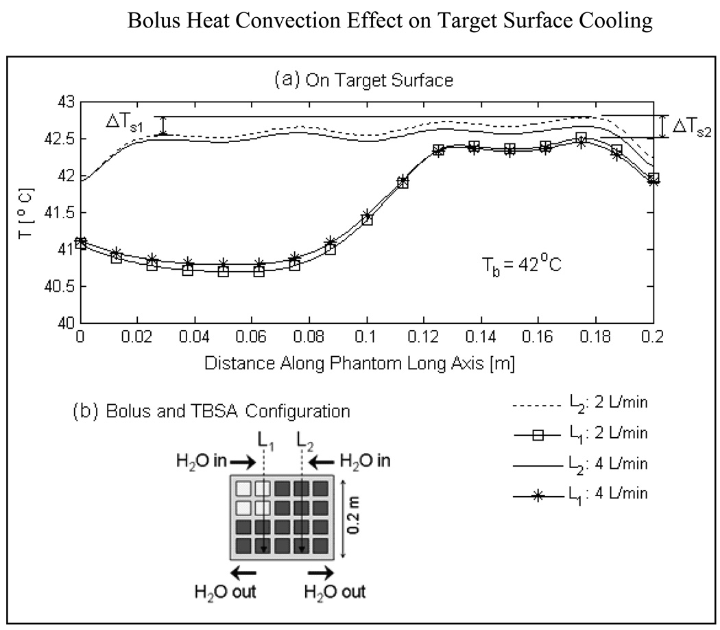
Fig 8a shows the temperature distributions on the surface of the tumor target along transects, L1 and L2 running parallel to the long axis of the elliptic phantom model and bolus flow direction for highly perfused tumor. The schematic illustration of Fig 8b indicates the location of L1 and L2. Surface temperature along L2 has contribution from all four DCC slot antennas above the DIDO bolus while temperature profile along L1 has contribution only from 2 DCC antennas. Close observation of the surface temperatures in Fig 8a indicates a slow but steady rise in tissue temperature along the direction of flow (i.e. vertically down from input to outlet). The successive rise in target surface temperature under the active DCC antennas denoted by ΔTs1 in Fig 8a is due to increase in bolus temperature as water flows beneath the DCC antennas radiating microwave power through the bolus into tumor target. The temperature gradient along the target surface, ΔTs1 is calculated to be 0.3 and 0.15°C respectively at 2 and 4 L/min along L2. Relatively smaller gradients were observed for the temperature profiles of L1 as the circulating water receives power deposition from only 2 of the 4 DCC elements along the flow path. The surface temperature variations, ΔTs1 and ΔTs2 observed along L1 and L2 in Fig 8a disappeared several mm deep inside the tumor target. The acceptably low variation in surface temperature observed at 2 L/min water flow rate indicates that the DIDO bolus maintains a nearly uniform flow distribution across the large bolus surface (500 cm2) and the existing water circulation system in our clinic should be adequate for the TBSA.
Fig 8.
Heat convection effect of DIDO waterbolus on target surface cooling and temperature homogeneity assuming high blood perfusion inside tumor target (ωb=5 kg/m3/s). (a) Target surface temperatures indicate a steady rise in temperature under the active DCCs (ΔTs1 ΔTs2) along the direction of water flow. Temperature rise observed on target surface due to increase in bolus temperature by the active DCC antennas is acceptably low at 2 and 4 L/min bolus flow rates and disappeared few mm inside tumor target.
Temperature and Thermal Dose Distributions
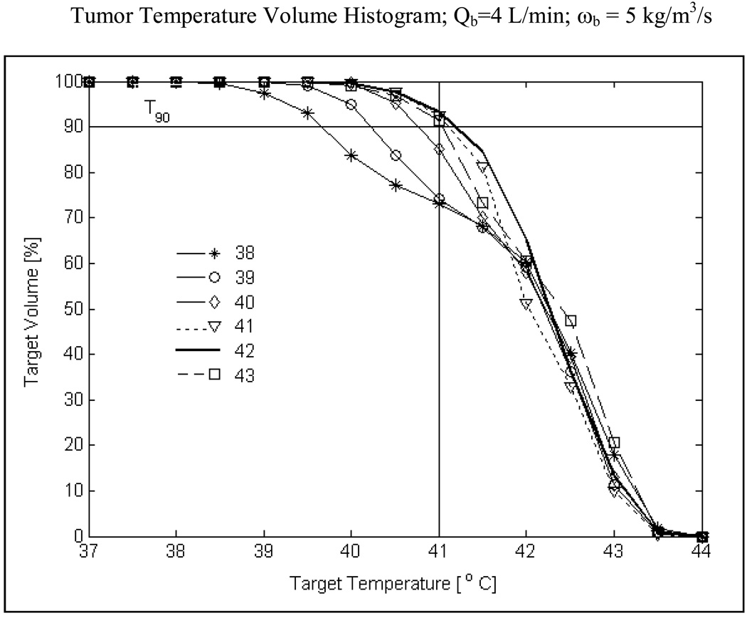
Fig 9 shows the temperature volume histogram inside highly perfused tumor extending 10 mm from surface including the skin. Simulation data of Fig 9 is obtained for R-TBSA with heating from the 5×4 DCC array at 4 L/min bolus flow rate, for bolus temperatures from 38–43°C. From Fig 9 it can be observed that the knee of the histogram curves is well defined at higher bolus temperatures (Tb>41°C). The double knee shape for Tb below 40°C is due to cooling of the first 3–4 mm of the superficial tissue inside the tumor target. An important observation is that T90 i.e., temperature that at least 90% of the target volume is above is maximum for a 42°C waterbolus (T90>41°C) and decreases for bolus temperatures above or below 42°C. The 3D temperature volume distributions of Fig 9 indicate that a 42°C waterbolus is optimal for tumor target extending 10 mm from surface. Similar curves were obtained for moderate and intermediate blood perfusion inside tumor target.
Fig 9.
Temperature volume histogram inside tumor target extending 10 mm from surface (including surface) with severe blood perfusion calculated for varying bolus inlet temperature. T90 value i.e., temperature that 90% of the target volume is above in Fig 9 for the worst case scenario (ωb=5 kg/m3/s) anticipated during hyperthermia indicates a maximum for 42°C water bolus and decreasing values for lower and higher bolus temperatures.
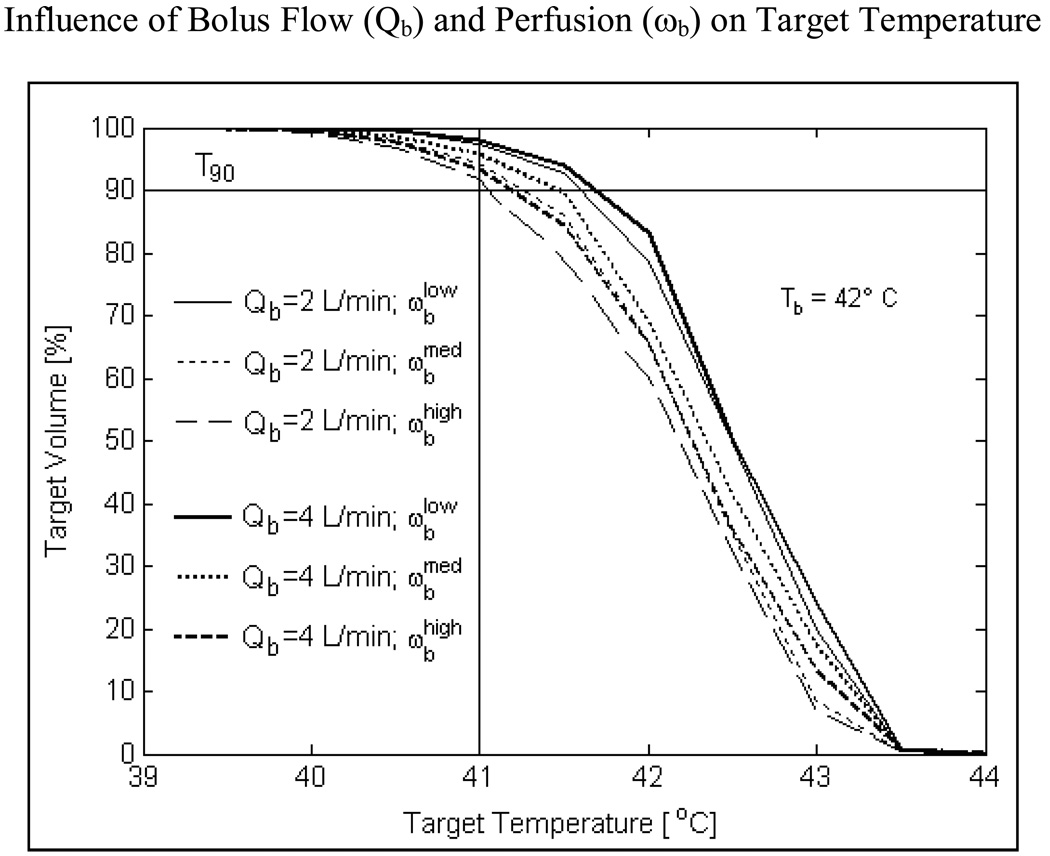
Fig 10 shows the influence of blood flow and bolus flow rate on temperature volume distributions inside a tumor target extending 10 mm from the surface for a 42 °C water bolus. As blood perfusion is varied from 2–5 kg/m3/s, T90 inside the tumor target varies from 41.1–41.6°C at 2 L/min and 41.2–41.7°C at 4 L/min bolus flow rate. Negligible difference in T90 values calculated at 2 and 4 L/min bolus flow rates for varying perfusion inside tumor target reinforces the prior observation (Fig 8) that 2 L/min should be adequate for TBSA applicators at least up to 875 cm2 surface areas.
Fig 10.
Influence of DIDO bolus flow rate and blood perfusion on temperature volume histogram inside tumor target extending 10 mm from surface. Simulations of R-TBSA with 5×4 DCC heating array for a 42°C bolus indicate that, heating inside the target volume is significantly influenced by tumor blood perfusion (ωb) more than the flow rate (Qb) inside the DIDO bolus.
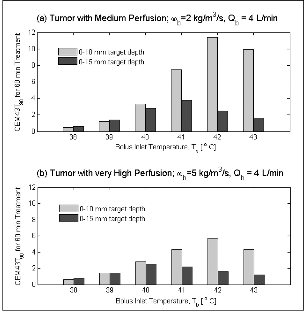
Fig 11 shows the influence of bolus temperature on the 90th percentile cumulative thermal dose (CEM43T90) delivered to medium and very highly perfused tumor targets during a 60 minute hyperthermia treatment. For tumor targets extending 10 mm from the surface, thermal dose was the highest for the 42°C bolus and decreased for higher or lower bolus temperature. For tumors that extend deeper (i.e., 0–15 mm from surface), maximum CEM43T90 thermal dose was delivered with 40°C bolus for tumor targets with very high blood perfusion. A similar shift in the maximum CEM43T90 occurs for tumor targets with moderate blood perfusion. Volume thermal dose of Fig 11 suggest the use of 41–42°C bolus for tumor targets that extend 10 mm from the surface and lower bolus temperatures of 39–40°C for tumor targets that extend 15 and even 20 mm from surface.
Fig 11.
Influence of bolus temperature on thermal dose (CEM43T90) delivered by r-TBSA to tumor targets of varying volumes for 60 minutes treatment duration. Thermal dose distributions indicate shift in the maximum CEM43T90 towards lower bolus temperatures (≤ 41 °C) for deeper targets compared to higher bolus temperatures (> 41 °C) for shallow targets (0–10 mm) from surface.
Discussion
The feasibility of simultaneous thermoradiotherapy reported in Phase I/II clinical trials (Moros et al., 1995b; Myerson et al., 1999) motivated the development of superficial hyperthermia devices for concurrent thermoradiotherapy (Novak et al., 2005; Stauffer et al., 2005; Taschereau et al., 2004). In recent years, the low profile CMA applicator designed for superficial hyperthermia with external beam radiation has spawned the development of a thermobrachytherapy surface applicator (TBSA) capable of sequential or simultaneous thermobrachytherapy. One advantage of HDR brachytherapy over external beam radiation for superficial chestwall recurrence is the ability to deliver well-localized radiation dose with minimal radiation morbidity to underlying critical organs (lungs, heart). In addition, spatially varying radiation dose can be delivered in a single treatment across a large surface area of the contoured chest wall by optimizing the dwell time and position of the HDR radiation source moving inside the array of parallel brachytherapy catheters (Sharma et al., 1997). Preliminary HDR brachytherapy treatment planning results of TBSA on CT torso phantom have demonstrated the feasibility of concurrent thermoradiotherapy (Craciunescu et al., 2009). In this work, we investigate the temperature distributions possible in 10–15 mm deep target lesions using TBSA applicators, taking into account several parameters that are known a-priori to impact thermal dose delivery.
Numerical simulations and experimental data of Lucite cone applicator (LCA) and CFMA microwave superficial heating devices operating at 433 MHz have assessed the role of bolus temperature and thickness on SAR and temperature distributions in planar tissue models (Kok et al., 2009; Lee et al., 2004; Van Der Gaag et al., 2006). Thermal models reported in these works approximate fluid flow inside the bolus with a constant convection coefficient which implies uniform fluid flow across the bolus. In this work, we incorporate bolus heat convection effects by solving full 3D computational fluid dynamics equations inside the water bolus (Arunachalam et al., 2009b). Fluid flow inside the bolus flow channels and open cell filter foam are appropriately modeled by the incompressible Navier Stokes Eqn (3) and Brinkman’s Eqn (4) for porous media respectively. 3D temperature volume distributions maintained by the TBSA inside predefined tumor target volumes of the chestwall of an elliptic torso phantom are studied by solving the heat convection equation inside the bolus (Eqn 5) and Pennes heat transfer equation (Eqn 6) inside the torso phantom. Numerous thermal simulations were carried out to assess the ability of TBSA to selectively deposit SAR inside the tumor target and evaluate factors affecting the thermal dose delivered to the target disease.
Due to close proximity of chestwall disease to ribs, heart and lungs, power deposited by CMA applicators inside the predefined tumor targets were studied for R- and L-TBSA of varying size (500–875 cm2) and shape. 2D SAR-depth distributions of R-TBSA in Fig 3 indicate rapid attenuation of the 915 MHz EM waves inside the target with maximum SAR on the tissue surface. SAR-volume histograms demonstrate that 90% of the tumor target receives at least 15% of the peak SAR, and SAR decays to 1% 3–4 cm from the surface. 3D SAR distributions of Fig 4–Fig 5 indicate nearly uniform spatial distribution underneath the active DCC antennas, with >90% of the tumor surface receiving ≥75% of SARmax. The SAR patterns of R-TBSA and L-TBSA for varying tumor size (500–875 cm2) and shape demonstrate the ability to deliver uniform localized power deposition inside tumor target sparing adjacent normal tissue and critical organs from heat and radiation induced damages. Furthermore, the conformal power depositions observed in Fig 3–Fig 5 indicate that TER enhancement occurs only inside the predefined target disease during simultaneous thermobrachytherapy.
Thermal simulations carried out for varying water bolus temperature (Tb), bolus flow rate (Qb) and blood perfusion (ωb) inside the target reveal several interesting observations. Of the three factors, inlet temperature of a DIDO water bolus has the highest impact on the quality of hyperthermia treatment delivered by the TBSA (Fig 6, Fig 9, Fig 11). Fig 11 summarizes the T90 values calculated for the 500 cm2 large R-TBSA for varying target volumes, bolus inlet temperatures (Tb) and tumor blood perfusion (ωb) under hyperthermic conditions at 4 L/min bolus flow rate. Similar T90 values were calculated at 2 L/min bolus flow rate. Irrespective of bolus flow rate and blood perfusion inside the tumor target, higher bolus temperature (Tb≥41°C) produces a peak 2–3 mm below the target surface (Fig 6) and delivers a higher overall thermal dose to the entire target extending 10 mm from surface (Fig 9, Fig 11). At lower bolus temperature (Tb<41°C), maximum temperatures occur further down (4–5 mm from surface - Fig 6), which lowers thermal dose in tissues close to the surface and raises the thermal dose of deeper tissues up to 15–20mm from surface (Fig 9, Fig 11). Similar observations were reported for the 433 MHz Lucite cone applicator (LCA) arrays designed for treating superficial disease extending 0–4 cm from surface (Van Der Gaag et al., 2006). The 3D thermal simulations of LCA for a planar tissue model indicated 41–42 °C waterbolus temperature to be optimal for disease extending 0–1 cm and lower bolus temperatures of 38–41 °C for disease extending 0–2 cm from surface which agrees with the results of this study.
Temperature depth profiles of Fig 7 and temperature volume histograms of Fig 10 clearly demonstrate the influence of blood perfusion on target temperature elevation to 40–44 °C. A higher blood perfusion rate reduces the target heating extent by few mm (Fig 7). As a result, lower T90 values and CEM43T90 thermal dose are calculated for tumor targets with higher blood perfusion (Fig 10–11). Blood perfusion is an uncontrolled phenomenon and heat lost due to blood flow can only be compensated to an extent by adjusting the power radiated by individual DCC elements of the CMA based on perfusion images and thermal feedback back from fiberoptic temperature probes (Stauffer et al., 1994) during hyperthermia treatment.
Non-uniform flow velocity and lower flow rates (1.5 L/min) inside a previous bolus design with water inlet on one side only resulted in higher temperature variation across the surface. This is due to inadequate heat transfer between the tissue and water flowing inside the bolus with single inlet and outlet flow channels under the active DCC antennas (Birkelund et al., 2009). This earlier work motivated the design of DIDO water boluses with wider flow channels that can maintain nearly uniform flow distribution and support higher flow rates (≥2 L/min) thereby minimizing target surface temperature variation even with variable SAR as in Fig 5 (Arunachalam et al., 2009b). Temperature distributions on the target surface in Fig 8a for varying flow rates inside the DIDO water bolus indicate only a small rise in peak temperature (ΔTs1≤0.3°C) as water flows underneath the active DCC antennas. This acceptably low surface temperature gradient calculated at 2 L/min disappeared by 3 mm depth into the target. Negligible difference in surface temperature distributions of Fig 8 and T90 values of Fig 10 for 2 and 4 L/min flow rates indicate that 2 L/min is adequate for the TBSA up to 875 cm2.
Finally, the thermal dose (CEM43T90) delivered by TBSA in Fig 11 for various depth tumors underscores the significance of bolus temperature on thermal dosimetry. Dosimetric characterization of TBSA applicators indicated exponentially decreasing radiation dose inside tumor targets with 20–30% overdose delivered to the target surface relative to the minimum tumor dose at depth (Craciunescu et al., 2009; Taschereau et al., 2004). Theoretical studies of ionizing dose distribution in pre-irradiated superficial tissues with external beam radiation for simultaneous thermoradiotherapy using CFMA also indicated maximum radiation dose to skin (Gelvich et al., 2006). HDR surface mold brachytherapy of pre-irradiated chestwall recurrence in post mastectomy patients indicated 88% complete regression and 12% partial response (Sharma et al., 1997). This is the only clinical study available in literature on the use of HDR brachytherapy for pre-irradiated chestwall recurrence. All patients in this study reportedly had RTOG/EORTC Grade II-III acute radiation reactions that healed within 4–6 weeks after completion of HDR treatment. Another study employing pulse dose rate (PDR) brachytherapy surface molds for macroscopic pre-irradiated breast cancer local chestwall recurrence reported actuarial 1, 2 and 3 year local recurrence free survival rates as 89%, 81% and 75% and Grade III acute reactions as per RTOG/EORTC score that healed within 4–6 weeks of PDR treatment (Harms et al., 2001). These findings combined with our experimental work of TBSA on CT torso phantom indicate that since radiation dose is maximum on the skin surface, it may be desirable to minimize TER enhancement in skin by using lower water temperature of the bolus, to move the peak TER below the skin surface with lower radiation dose. From Fig 6 and Fig 11, it can be observed that lower thermal dose and TER enhancement can be delivered to the first few mm of the target surface during simultaneous thermobrachytherapy by reducing the bolus temperature to 39–40 °C which effectively allows treatment of deeper targets to 20 mm depth. Otherwise, a 41–42 °C waterbolus could be used for simultaneous thermobrachytherapy treatment of more superficial tumors extending only 5–10mm from surface.
The thermal simulation outcomes reported in this study should hold good for other superficial hyperthermia applicators employing conformal antenna arrays and a thin layer water bolus, when combined with external beam radiation or brachytherapy. Thermal simulations of TBSA reported in this study indicate that a 42°C water bolus and 2 L/min bolus flow rate are appropriate for chestwall recurrences extending 10–15 mm from the surface and, lower bolus temperatures (39–40 °C) are suggested for tumors extending deeper (20 mm from surface) or for patients where skin toxicity may be a treatment limiting factor.
Conclusion
A comprehensive thermal analysis was carried out to evaluate the heating characteristics of large area conformal thermobrachytherapy surface applicators (TBSA). Recently introduced Dual-Input Dual-Output (DIDO) water boluses were found to produce acceptably low variation in surface temperature for either 2 or 4 L/min flow rates inside the bolus. Perfusion inside the tumor target will remain an unknown and uncontrollable parameter which can only be compensated with measured thermometric feedback. Considering practical ranges of tissue perfusion, waterbolus flow rate, and water temperature, the bolus inlet temperature has the strongest influence on thermal dose distribution in tissue. Higher thermal dose can be delivered to superficial tumor targets during simultaneous thermobrachytherapy treatment using a 42°C water bolus while lower bolus temperatures of 39–40°C may be chosen to reduce TER in the most sensitive skin where maximum radiation dose is delivered and to extend thermal enhancement of radiation dose deeper.
Acknowledgements
This effort was supported by NIH Grants R44CA104061 and RO1 CA70761. The authors would like to thank Edward Markewitz with Bionix Development Corporation for his effort on fabrication of the TBSA. We also acknowledge the generous donations of modeling programs from Ansoft Corp and, 3D segmentation tools from VSG Inc.
References
- Arunachalam K, Craciunescu OI, Maccarini P, Schlorff J, Markewitz E, Stauffer PR. Progress on thermobrachytherapy surface applicator for superficial tissue disease. In: Ryan TP, editor. Energy-based Treatment of Tissue and Assessment V, Proceedings of SPIE. Bellingham WA: SPIE Press; 2009a. 71810C. [DOI] [PMC free article] [PubMed] [Google Scholar]
- Arunachalam K, Maccarini P, Juang T, Gaeta C, Stauffer PR. Performance evaluation of a conformal thermal monitoring sheet sensor array for measurement of surface temperature distributions during superficial hyperthermia treatments. Int J Hyperthermia. 2008;24:313–325. doi: 10.1080/02656730701881133. [DOI] [PMC free article] [PubMed] [Google Scholar]
- Arunachalam K, Maccarini P, Schlorff J, Birkelund Y, Jacobsen S, Stauffer PR. Design of a Water Coupling Bolus with Improved Flow distribution for Multielement Superficial Hyperthermia Applicators. Int J Hyperthermia. 2009b;25:554–565. doi: 10.3109/02656730903124506. [DOI] [PMC free article] [PubMed] [Google Scholar]
- Bars ML, Worster MG. Interfacial conditions between a pure fluid and a porous medium: implications for binary alloy solidification. Journal of Fluid Mechanics. 2006;550:149–173. [Google Scholar]
- Berenger J. A perfectly matched layer for the absorption of electromagnetic waves. Journal of Computational Physics. 1994;114:185–200. [Google Scholar]
- Birkelund Y, Jacobsen S, Arunachalam K, Maccarini P, Stauffer PR. Flow patterns and heat convection in a rectangular water bolus for use in superficial hyperthermia. Physics in Medicine and Biology. 2009;54:3937–3953. doi: 10.1088/0031-9155/54/13/001. [DOI] [PMC free article] [PubMed] [Google Scholar]
- Cheng DK. Field and Wave Electromagnetics. Reading MA: Addison-Wesley Pub. Co; 1989. [Google Scholar]
- Craciunescu OI, Arunachalam K, Steffey BA, Maccarini P, Schlorff J, Stauffer PR. Dosimetric Characterization Of The Thermobrachytherapy Surface Applicator; American Brachytherapy Society Annual Meeting 2009; Toronto Canada. 2009. [Google Scholar]
- Dewey WC. Arrhenius relationships from the molecule and cell to the clinic. International Journal of Hyperthermia. 1994;10:457–483. doi: 10.3109/02656739409009351. [DOI] [PubMed] [Google Scholar]
- Gelvich EA, Klimanov VA, Kramer-Ageev EA, Mazokhin VN. Computational evaluation of changes in ionizing radiation dose distribution in tissues caused by EM applicators when external radiation and hyperthermia act simultaneously. Int J Hyperthermia. 2006;22:343–352. doi: 10.1080/02656730600661750. [DOI] [PubMed] [Google Scholar]
- Gelvich EA, Mazokhin VN. Resonance effects in applicator water boluses and their influence on SAR distribution patterns. International Journal of Hyperthermia. 2000;16:113–128. doi: 10.1080/026567300285321. [DOI] [PubMed] [Google Scholar]
- Harms W, Krempien R, Hensley FW, Berns C, Wannenmacher M, Fritz P. Results of Chest Wall reirradiation using pulsed-dose-rate (PDR) Brachytherapy Molds for Breast Cancer Local Recurrences. International Journal of Radiation Oncology Biology Physics. 2001;49:205–210. doi: 10.1016/s0360-3016(00)01360-2. [DOI] [PubMed] [Google Scholar]
- Jones E, Oleson J, Prosnitz L, Samulski T, Vujaskovic Z, Yu D, Sanders L, Dewhirst MW. Randomized trial of hyperthermia and radiation for superficial tumors. Journal of Clinical Oncology. 2005;23:3079–3085. doi: 10.1200/JCO.2005.05.520. [DOI] [PubMed] [Google Scholar]
- Jones EL, Samulski TV, Dewhirst MW, Alvarez-Secord A, Berchuck A, Clarke-Pearson D, Havrilesky LJ, Soper J, Prosnitz LR. A pilot Phase II trial of concurrent radiotherapy, chemotherapy, and hyperthermia for locally advanced cervical carcinoma. Cancer. 2003;98:277–282. doi: 10.1002/cncr.11475. [DOI] [PubMed] [Google Scholar]
- Juang T, Stauffer P, Neuman D, Schlorff J. Multilayer conformal applicator for microwave heating and brachytherapy treatment of superficial tissue disease. International Journal of Hyperthermia. 2006;22:527–544. doi: 10.1080/02656730600931815. [DOI] [PubMed] [Google Scholar]
- Kok HP, De Greef M, Correia D, Zum Vorde Sive Vording PJ, Van Stam G, Gelvich EA, Bel A, Crezee J. FDTD simulations to assess the performance of CFMA-434 applicators for superficial hyperthermia. Int J Hyperthermia. 2009;25:462–476. doi: 10.1080/02656730903008493. [DOI] [PubMed] [Google Scholar]
- Lee WM, Gelvich EA, van der Baan P, Mazokhin VN, van Rhoon GC. Assessment of the performance characteristics of a prototype 12-element capacitive contact flexible microstrip applicator (CFMA-12) for superficial hyperthermia. Int J Hyperthermia. 2004;20:607–624. doi: 10.1080/02656730410001695915. [DOI] [PubMed] [Google Scholar]
- Maccarini P, Arunachalam K, Martins C, Stauffer P. Size Reduction and Radiation Pattern Shaping of Conformal Microwave Array Hyperthermia Applicators using Multi-fed DCC Slot Antennas. In: Ryan TP, editor. Proc. of SPIE. San Jose: Bellingham WA: SPIE Press; 2009. 7181O7-1-9. [DOI] [PMC free article] [PubMed] [Google Scholar]
- Maccarini PF, Rolfsnes HO, Johnson J, Neuman DG, Jacobsen S, Stauffer PR. Electromagnetic Optimization of Dual Mode Antennas for Radiometry Controlled Heating of Superficial Tissue. In: Ryan TP, editor. Proc. of SPIE. San Jose: SPIE Press; 2005. pp. 71–78. [Google Scholar]
- Moros EG, Straube WL, Klein EE, Yousaf M, Myerson RJ. Simultaneous delivery of electron beam therapy and ultrasound hyperthermia utilizing scanning reflectors: a feasibility study. International Journal of Radiation Oncology Biology Physics. 1995a;31:893–904. doi: 10.1016/0360-3016(94)00469-2. [DOI] [PubMed] [Google Scholar]
- Moros EG, Straube WL, Klein EE, Myerson RJ. Clinical system for simultaneous external superficial microwave hyperthermia and cobalt-60 radiation. Int J Hyperthermia. 1995b;11:11–26. doi: 10.3109/02656739509004944. [DOI] [PubMed] [Google Scholar]
- Myerson RJ, Straube WL, Moros EG, Emami BN, Lee HK, Perez CA, Taylor ME. Simultaneous superficial hyperthermia and external radiotherapy: Report of thermal dosimetry and tolerance to treatment. Int J Hyperthermia. 1999;15:251–266. doi: 10.1080/026567399285639. [DOI] [PubMed] [Google Scholar]
- Neuman DG, Stauffer PR, Jacobsen S, Rossetto F. SAR pattern perturbations from resonance effects in water bolus layers used with superficial microwave hyperthermia applicators. International Journal of Hyperthermia. 2002;18:180–193. doi: 10.1080/02656730110119198. [DOI] [PubMed] [Google Scholar]
- Novak P, Moros EG, Straube WL, Myerson RJ. SURLAS: a new clinical grade ultrasound system for sequential or concomitant thermoradiotherapy of superficial tumors: applicator description. Medical Physics. 2005;32:230–240. doi: 10.1118/1.1835572. [DOI] [PubMed] [Google Scholar]
- Novak P, Penagaricano JA, Volodymyr N, Corry P, Moros EG. Influence of the SURLAS applicator on radiation dose distributions during simultaneous thermoradiotherapy with helical tomotherapy. Physics in Medicine and Biology. 2008;53:2509–2522. doi: 10.1088/0031-9155/53/10/004. [DOI] [PubMed] [Google Scholar]
- Overgaard J. Simultaneous and sequential hyperthermia and radiation treatment of an experimental tumor and its surrounding normal tissue in vivo. International Journal of Radiation Oncology Biology Physics. 1980;6:1507–1517. doi: 10.1016/0360-3016(80)90008-5. [DOI] [PubMed] [Google Scholar]
- Perez CA, Pajak T, Emami B, Hornback NB, Tupchong L, Rubin P. Randomized phase III study comparing irradiation and hyperthermia with irradiation alone in superficial measurable tumors. Final report by the Radiation Therapy Oncology Group. Am J Clin Oncol. 1991;14:133–141. doi: 10.1097/00000421-199104000-00008. [DOI] [PubMed] [Google Scholar]
- Roemer RB. In: Thermal Dosimetry and Treatment Planning. Gautherie M, editor. Berlin: Springer-Verlag; 1990. pp. 119–214. [Google Scholar]
- Rossetto F, Stauffer PR. Effect of complex bolus-tissue load configurations on SAR distributions from dual concentric conductor applicators. IEEE Transactions on Biomedical Engineering. 1999;46:1310–1319. doi: 10.1109/10.797991. [DOI] [PubMed] [Google Scholar]
- Rossetto F, Stauffer PR, Manfrini V, Diederich CJ, Biffi Gentili G. Effect of practical layered dielectric loads on SAR patterns from dual concentric conductor microstrip antennas. International Journal of Hyperthermia. 1998;14:513–534. doi: 10.3109/02656739809018254. [DOI] [PubMed] [Google Scholar]
- Seegenschmiedt MH, Fessenden P, Vernon CC, editors. Thermoradiotherapy and thermochemotherapy: volume 1 biology, physiology, and physics. vol 1. Berlin, Heidelberg: Springer-Verlag; 1995. [Google Scholar]
- Seegenschmiedt MH, Fessenden P, Vernon CC. Thermoradiotherapy and thermochemotherapy: volume 2, clinical applications. Berlin, New York: Springer-Verlag; 1996. [Google Scholar]
- Sharma SC, Negi PS, Singh DP, Munjal RK, Goyal D, Patel FD. High dose rate surface mould brachytherapy for superficial localised chest wall recurrences in postmastectomy carcinoma breast patients. Journal of Clinical Radiotherapy and Oncology. 1997;12:1–6. [Google Scholar]
- Sherar M, Liu FF, Pintilie M, Levin W, Hunt J, Hill R, Hand J, Vernon C, van Rhoon G, van der Zee J, Gonzalez DG, van Dijk J, Whaley J, Machin D. Relationship between thermal dose and outcome in thermoradiotherapy treatments for superficial recurrences of breast cancer: data from a phase III trial. International Journal of Radiation Oncology, Biology, Physics. 1997;39:371–380. doi: 10.1016/s0360-3016(97)00333-7. [DOI] [PubMed] [Google Scholar]
- Sneed PK, Stauffer PR, Li GC. In: Textbook of Radiation Oncology. Second Edition. Leibel SA, Phillips TL, editors. Philadelphia: W B Saunders Co.; 2004. pp. 1569–1596. [Google Scholar]
- Sneed PK, Stauffer PR, McDermott MW, Diederich CJ, Lamborn KR, Prados MD, Chang S, Weaver KA, Spry L, Malec MK, Lamb SA, Voss B, Davis RL, Wara WM, Larson DA, Phillips TL, Gutin PH. Survival benefit of hyperthermia in a prospective randomized trial of brachytherapy boost +/− hyperthermia for glioblastoma multiforme. International Journal of Radiation Oncology, Biology and Physics. 1998;40:287–295. doi: 10.1016/s0360-3016(97)00731-1. [DOI] [PubMed] [Google Scholar]
- Stauffer P, Schlorff J, Taschereau R, Juang T, Neuman D, Maccarini P, Pouliot J, Hsu J. Combination applicator for simultaneous heat and radiation. Conf Proc IEEE Eng Med Biol Soc. 2004;4:2514–2517. doi: 10.1109/IEMBS.2004.1403724. [DOI] [PubMed] [Google Scholar]
- Stauffer PR. Evolving technology for thermal therapy of cancer. Int J Hyperthermia. 2005;21:731–744. doi: 10.1080/02656730500331868. [DOI] [PubMed] [Google Scholar]
- Stauffer PR, Diederich CJ, Sneed PK, Fidel JA, Phillips TL. Preliminary clinical experience with planar and conformal microwave array applicators for hyperthermia; 14th North American Hyperthermia Society Meeting; Nashville TN. 1994. p. 113. [Google Scholar]
- Stauffer PR, Leoncini M, Manfrini V, Gentili GB, Diederich CJ, Bozzo D. Dual concentric conductor radiator for microwave hyperthermia with improved field uniformity to periphery of aperture. IEICE Transactions on Communications. 1995;E78-B:826–835. [Google Scholar]
- Stauffer PR, Schlorff JL, Juang T, NEuman DG, Johnson JE, Maccarini PF, Pouliot J. Progress on system for applying simultaneous heat and brachytherapy to large-area surface disease. In: Ryan TP, editor. SPIE BIOS 2005. San Jose: SPIE Press; 2005. p. 15. [Google Scholar]
- Taschereau R, Stauffer PR, Hsu IC, Schlorff JL, Milligan AJ, Pouliot J. Radiation dosimetry of a conformal heat-brachytherapy applicator. Technology in Cancer Research and Treatment. 2004;3:347–358. doi: 10.1177/153303460400300404. [DOI] [PubMed] [Google Scholar]
- Van De Kamer JB, Van Wieringen N, De Leeuw AAC, Lagendijk JJW. The significance of accurate dielectric tissue data for hyperthermia treatment planning. International journal of hyperthermia. 2001;17:123–142. doi: 10.1080/02656730150502297. [DOI] [PubMed] [Google Scholar]
- Van Der Gaag ML, De Bruijne M, Samaras T, Van Der Zee J, Van Rhoon GC. Development of a guideline for the water bolus temperature in superficial hyperthermia. Int J Hyperthermia. 2006;22:637–656. doi: 10.1080/02656730601074409. [DOI] [PubMed] [Google Scholar]
- van der Zee J, Gonzalez-Gonzalez D, van Rhoon GC, van Dijk JDP, van Putten WLJ, Hart AAM. Comparison of radiotherapy alone with radiotherapy plus hyperthermia in locally advanced pelvic tumours: a prospective, randomised, multicentre trial. Lancet. 2000;355:1119–1125. doi: 10.1016/s0140-6736(00)02059-6. [DOI] [PubMed] [Google Scholar]
- Vernon CC. Results of recent randomized clinical hyperthermia trials in Europe--success story. International Journal of Radiation Oncology Biology Physics. 1994;30 Suppl. 1:115. [Google Scholar]
- Vernon CC, Hand JW, Field SB, Machin D, Whaley JB, van der Zee J, van Putten WLJ, van Rhoon GC, van Dijk JDP, Gonzalez-Gonzalez D, Liu FF, Goodman P, Sherar M. Radiotherapy with or without hyperthermia in the treatment of superficial localized breast cancer: Results from five randomized controlled trials. International Journal of Radiation Oncology, Biology and Physics. 1996;35:731–744. doi: 10.1016/0360-3016(96)00154-x. [DOI] [PubMed] [Google Scholar]
- Wissler EH. Pennes’ 1948 paper revisited. Journal of Applied Physiology. 1998;85:36–42. doi: 10.1152/jappl.1998.85.1.35. [DOI] [PubMed] [Google Scholar]
- Zienkiewicz OC, Taylor RL, Nithiarasu P. The Finite Element Method for Fluid Dynamics. Elsevier; 2005. [Google Scholar]


