Abstract
High frequency ultrasonic imaging is considered by many to be the next frontier in ultrasound. It has many clinical applications ranging from imaging the eye and skin to small animal imaging. Small animal imaging has recently generated intense interest for the purpose of evaluating the efficacy of drugs and gene therapy. Commercial high frequency scanners often termed “ultrasonic biomicroscope”, or UBM, all use mechanically scanned single element transducers at frequencies between 30 to 60 MHz with a frame rate of 30 frames/second or lower. To alleviate problems with UBMs which include mechanical motion and fixed focusing, high frequency linear arrays and imaging systems in the 20–50 MHz range have been developed. In this paper, current efforts in the development of high frequency ultrasonic imaging will be reviewed and potential biomedical applications discussed.
Keywords: high frequency scanner, small animal imaging, ultrasonic backscatter microscope
Introduction
Ultrasonic imaging is one of the most important, developing diagnostic tools today. State-of-the-art ultrasonic scanners offer real-time gray scale images of anatomical details with millimeter spatial resolution superimposed on which a map of Doppler blood flow information is displayed in full color [1-4]. Clinical applications of these devices are still expanding and the operating frequencies of these devices are seeming to inch higher and higher. High frequency (HF) imaging (higher than 30 MHz) yields improved spatial resolution at the expense of a shallower depth of penetration [3,5,6]. Conventional ultrasonic imaging systems typically use frequencies from 2 to 15 MHz. To improve spatial resolution, one obvious strategy would be to increase the frequency. The axial resolution is determined by the pulse duration or the bandwidth of the pulse. The lateral resolution at the focal point is determined by the product of the f-number, defined as the ratio of the focal distance to the spatial dimension of the transducer, and the wavelength. For a fixed number of cycles per pulse, an increase in frequency would result in a reduction in wavelength and thus pulse duration. As ultrasound frequency is increased to 50 MHz, an axial resolution and lateral resolution of better than 20 and 100 μm for an f-number of 2.9 can be achieved. The price to be paid is an increase in attenuation because ultrasound attenuation in tissues is approximately linearly proportional to frequency [1-4]. At 50 MHz, the depth of penetration for most tissues would be limited to 8–9 mm. There are a number of clinical problems that may benefit from high frequency ultrasonic imaging [6]. Intravascular imaging with probes mounted on catheter tips at frequencies higher than 20 MHz with the highest frequency being 60 MHz has been used to characterize atherosclerotic plaque and to guide stent placement and angioplastic procedures [7]. The medical efficacy of ultrasonic imaging has been demonstrated in the anterior segments of the eye at frequencies higher than 50 MHz in diagnosing glaucoma, ocular tumors, and in assisting refractive surgery [6]. The availability of a noninvasive imaging tool for dermatological applications could reduce the number of biopsies that are associated with patient discomfort and could better demarcate tumor involvement. Small animal imaging is another frontier of HF ultrasound. Small animal imaging has been of intense interest recently because of the utilization of such small animals as mice and zebrafish in drug and gene therapy research. Micro magnetic resonance imaging (mircoMRI), micro computed tomography (microCT), optical coherent tomography (OCT) and micro positron emission tomography (microPET) have all been developed to meet this need. Ultrasound thus far has only played a limited role.
Ultrasonic Biomicroscope (UBM)
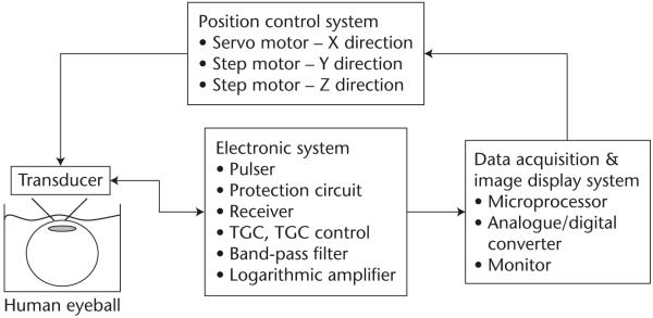
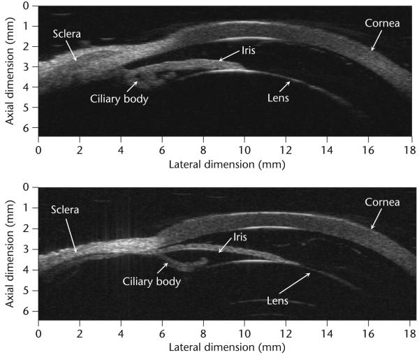
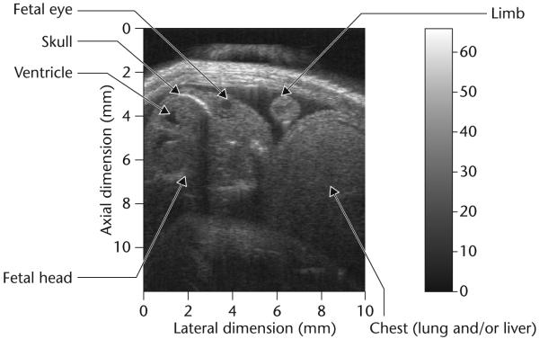
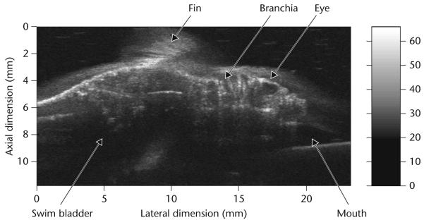
Almost all current HF ultrasound imaging devices, dubbed ultrasound biomicroscopes (UBMs) [6] use mechanically scanned single element transducers which are either piezoelectric polymer PVDF or the copolymer P(VDF-TrFE) based or lithum niobate based [3,8,9]. The construction of a UBM is identical to that of a static B-mode scanner [3]. A block diagram of such a system is shown in Fig. 1. The positional control of the transducer must have an accuracy of a few μm. The analog to digital converter (ADC) typically has a sampling frequency higher than 200 MHz to more than 8 bits. UBMs have been used to image anterior segments of the eye, skin and small animals like mice and zebrafish. Fig. 2 shows two UBM images of an excised eye obtained at 40 and 80 MHz. The improvement in spatial resolution and image quality as the frequency is increased is apparent. Figs 3 and 4 shows respectively the image of a mouse fetus and a zebrafish. Scanning can also be achieved by better utilizing the focus of the transducer by incrementally moving the transducer in the axial direction, called B-D (D stands for depth) mode scan. A composite image is formed by combing the focused segments of multiple images acquired as the transducer is moved in the axial direction. This mode of scanning improves lateral resolution by sacrificing frame rate. Commercial UBMs can achieve a frame rate of 30 frames/second because the excursion range is relatively small. This is still inadequate for imaging the hearts of small animals like rats or mice which beat at a rate of 4–6 beats/second, much faster than the typical 1–2 beats/second of the human heart rate. Mechanical scanning of a single element transducer has other drawbacks: poorer resolution and motion of the probe. Single element transducers can only produce beams with a fixed focus which means the spatial resolution of the device is best only within the depth of focus, i.e. in a very tight zone and degrades rapidly beyond the focal point. Mechanical motion of the transducer limits the frame rate, is unreliable, and may cause discomfort and, at worst, may be hazardous to the patient. These problems can be overcome by adopting linear arrays.
Fig. 1.
Block diagram of an ultrasonic biomicroscope (UBM) system.
Fig. 2.
Ultrasonic biomicroscope (UBM) images of an excised eye at 40 and 80 MHz.
Fig. 3.
Ultrasonic biomicroscope (UBM) image of a pregnant mouse at 45 MHz.
Fig. 4.
Ultrasonic biomicroscope (UBM) image of a zebrafish at 40 MHz.
There are almost a dozen manufacturers that produce UBMs for eye, skin and small animal imaging. Most notable for eye scanners are Quantel (US), Sonomed (US), Paradigm (US), Innovative Imaging (US), Ophthalmology Technology (Canada), and Tomey (Japan). A majority of skin scanners including Dynamic Imaging (UK), Longport (UK), and Cortex Technology (Denmark) are located in Europe. At present there is only one small animal scanner manufacturer which is Visualsonics (Canada). Presumably the market is so small that the big three GE, Siemens and Philips have not yet shown an interest in entering it.
HF Array Imaging
The problems facing mechanical scanners may be overcome by adopting either annular array or linear array technology. HF annular arrays which allow dynamic 2-D focusing are a partial solution to these problems [9-12]. Since mechanical motion is still involved for annular arrays, a better solution would be to use linear arrays which generate an image by electronically sweeping a beam [3,9,13-18]. Linear ultrasonic array systems have significant advantages over signal element and annular imaging systems which require mechanical scanning to form an image slice. Array systems use electronic scanning to form an image slice and therefore can achieve higher image frame rates. Also, the emitted sound beam can be steered and dynamically focused in the image plane. Finally, the lack of movable parts make these arrays less likely to be hazardous to patients. There are three major challenges in HF linear array fabrication: small kerf (the gap between two elements) width, large electrical impedance mismatch and increased crosstalk. In order to minimize grating lobes, typically in linear array and linear phased array design, the pitch that is the distance between the centers of two elements must be less than 1λ and 0.5λ respectively [3,4]. This means that the pitch must be less than 50 μm and 30 μm at 30 and 50 MHz. To insure good sensitivity in linear arrays, the element size should be made as large as possible. Therefore the kerf width should be made as small as possible, making it very difficult if not impossible to dice with current dicing machines. A confounding factor is that unless a suitable kerf filler is found, the crosstalk level will increase as a result of the smaller kerf width. It should be noted here that in phased arrays the element size should also be judiciously chosen to assure a broad steering angle.
Efforts are now underway to develop 20–50 MHz linear arrays [9,13-18]. Piezoelectric composites have been used by Ritter et al [13], Michau et al [14], Cannata et al [17] and Brown et al [18] in their designs. A new technology that utilizes micromachined electromechanical system (MEMS) technology called cMUT (capacitive micromachined ultrasonic transducer) appears to hold great promise [15,16]. Currently the pitch in HF linear array designs is greater than 1λ and their performance is not yet upon par with commercial linear arrays at lower frequencies. This means that much improvement in linear arrays in this frequency range can still be made. Developing linear arrays to 50 MHz or even higher frequencies and phased arrays at 30 MHz remains quite a challenge technically.
Linear arrays at 30–35 MHz that use 2-2 composites have been developed and tested [13,17]. The pitches were from 2λ to 1.2λ. The matching layers were prepared from 0–3 composites and epoxy. A lens made from the plastic TPX was used for elevation focusing. The arrays had a −6 d bandwidth of 50–60%, an insertion loss of −25 dB and an element-to-element crosstalk of less than −28 dB. Both an analog and a digital HF imaging systems consisting of 16 channels have been developed for the purpose of assessing the performance of these arrays [19]. An image of a mouse heart obtained in vivo is shown in Fig. 5. The lateral resolution is poor in the far field due to the small aperture. The frame rate however for this system is very high and can approach 400 frames/second. These systems are being expanded to 64 channels.
Fig. 5.
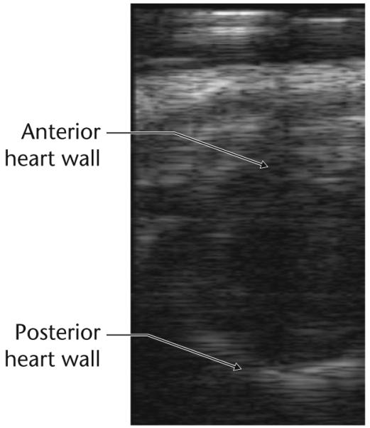
An image of mouse heart obtained in vivo with a 30 MHz linear array and a 16 channel analog imaging system.
A commercial linear array based small animal imaging system has been recently launched by Visualsonics (Canada). The system which is more expansive than most clinical scanners offers linear arrays with center frequencies ranging from 15 to 50 MHz.
HF ultrasound because of its smaller wavelength has been used to characterize cellular processes like apoptosis [20] and lens hardness in the eye [21,22]. Both the attenuation and sound velocity have been shown to be related to eye hardness. A potential clinical application in the latter is to assist the surgery in determining ultrasonic energy level during phaco-surgery.
Conclusion
This review paper discusses recent developments in HF ultrasonic imaging including transducers and systems at frequencies higher than 30 MHz. Potential preclinical and clinical applications are addressed. There is no reason not to believe that in the near future HF imaging systems with a capability similar to current clinical scanners will become more widely available and their applications expanded into other biomedical disciplines.
References
- 1.Zagzebski JM. Essentials of ultrasound physics. Mosby; St. Louis, MO: 1996. [Google Scholar]
- 2.Szabo T. Diagnostic ultrasound imaging: inside out. Elsevier; New York: 2004. [Google Scholar]
- 3.Shung KK. Diagnostic ultrasound: imaging and blood flow measurements. CRC Press; Boca Raton, Fl: 2006. [Google Scholar]
- 4.Cobbold RSC. Foundations of biomedical ultrasound. Oxford University Press; New York: 2007. [Google Scholar]
- 5.Pavlin CJ, Foster FS. Ultrasound microscopy of the eye. Springer-Verlag; New York: 1995. [Google Scholar]
- 6.Foster FS, Pavlin CJ, Harasiewicz KA, et al. Ultrasound Med Biol. Vol. 26. 2000. Advances in ultrasound biomicroscopy; pp. 1–27. [DOI] [PubMed] [Google Scholar]
- 7.Saijo Y, van der Steen AFW. Vascular ultrasound. Springer; Tokyo: 2003. [Google Scholar]
- 8.Cannata JM, Ritter TA, Chen WH, et al. Design of efficient, broadband single element (20–80 MHz) ultrasonic transducers for medical imaging applications. IEEE Trans Ultras Ferro Freq Cont. 2003;50:1548–57. doi: 10.1109/tuffc.2003.1251138. [DOI] [PubMed] [Google Scholar]
- 9.Shung KK, Cannata JM, Zhou QF. High frequency ultrasonic transducers and arrays. In: Safari A, Akdogan EK, editors. Piezoelectric and Acoustic Materials for Transducer Applications. Springer; New York: 2008. pp. 431–51. [Google Scholar]
- 10.Brown JA, Demore CEM, Lockwood GR. Design and fabrication of annular arrays for high frequency ultrasound. IEEE Trans Ultras Ferro Freq Cont. 2004;51:1010–7. doi: 10.1109/tuffc.2004.1324405. [DOI] [PubMed] [Google Scholar]
- 11.Ketterling JA, Aristizabal O, Turnbull DH, et al. Design and fabrication of a 40 MHz annular array transducer. IEEE Trans Ultras Ferro Freq Cont. 2005;52:672–9. doi: 10.1109/tuffc.2005.1428050. [DOI] [PMC free article] [PubMed] [Google Scholar]
- 12.Gottlieb EJ, Cannata JM, Hu CH, et al. Development of a high frequency (> 50 MHz) copolymer annular array ultrasound transducer. IEEE Trans Ultras Ferro Freq Cont. 2006;53:1037–45. doi: 10.1109/tuffc.2006.1632693. [DOI] [PubMed] [Google Scholar]
- 13.Ritter TA, Shrout TR, Tutwiler R, et al. A 30-MHz composite ultrasound array for medical imaging applications. IEEE Trans Ultras Ferro Freq Cont. 2002;49:217–30. doi: 10.1109/58.985706. [DOI] [PubMed] [Google Scholar]
- 14.Michau S, Maucharmp P, Dufait R. Piezocomposite 30 MHz linear array for medical imaging: design challenges and performances evaluation of 128 element array. 2004 IEEE Ultras Symp Proc. 2002:898–902. [Google Scholar]
- 15.Oralkan O, Hansen ST, Bayram B, et al. High-frequency CMUT arrays for high resolution medical imaging. 2004 IEEE Ultras Symp Proc. 2004:399–402. [Google Scholar]
- 16.Yeh DT, Oralkan O, Wygant IO, et al. High resolution imaging with high frequency 1-D linear CMUT arrays. 2005 IEEE Ultras Symp Proc. 2005:665–9. [Google Scholar]
- 17.Cannata JM, Williams JA, Zhou QF, et al. Development of a 35 MHz piezo-composite ultrasound array for medical imaging. IEEE Trans Ultras Ferro Freq Cont. 2005:52224–36. doi: 10.1109/tuffc.2006.1588408. [DOI] [PubMed] [Google Scholar]
- 18.Brown JA, Foster SF, Needles A, et al. Fabrication and performance of a 40 MHz linear array based on 1-3 composite with geometric focusing. IEEE Trans Ultras Ferro Freq Cont. 2007;54:1888–95. doi: 10.1109/tuffc.2007.473. [DOI] [PubMed] [Google Scholar]
- 19.Hu CH, Cannata JM, Yen JT, et al. Development of a real-time high frequency ultrasound beamformer for high frequency linear array transducers. IEEE Trans Ultras Ferro Freq Cont. 2006;53:317–23. doi: 10.1109/tuffc.2006.1593370. [DOI] [PubMed] [Google Scholar]
- 20.Kolios MC, Czarnota GJ, Lee M, et al. Ultrasonic spectral parameter characterization of apoptosis. Ultrasound Med Biol. 2002;28:589–97. doi: 10.1016/s0301-5629(02)00492-1. [DOI] [PubMed] [Google Scholar]
- 21.Huang CC, Ameri H, DeBoer C, et al. Evaluation of lens hardness in cataract surgery using high frequency ultrasonic parameters in vitro. Ultrasound Med Biol. 2007;33:1609–17. doi: 10.1016/j.ultrasmedbio.2007.05.002. [DOI] [PubMed] [Google Scholar]
- 22.Huang CC, Sun L, Daily SH, et al. High frequency ultrasonic characterization of human vocal cord tissue. J Acoust Soc Am. 2007;122:1827–32. doi: 10.1121/1.2756759. [DOI] [PubMed] [Google Scholar]


