Abstract
Computer-assisted navigation systems for hip resurfacing arthroplasty are designed to minimize the chance of implant malposition. However, there is little evidence computer navigation is useful in the presence of anatomical deformity. We therefore determined the accuracy of an image-free resurfacing hip arthroplasty navigation system in the presence of a pistol grip deformity of the head and femoral neck junction and of a slipped upper femoral epiphysis deformity. We constructed an artificial phantom leg from machined aluminum with a simulated hip and knee. The frontal and lateral plane implant-shaft angles for the guide wire of the femoral component reamer were calculated with the computer navigation system and with an electronic caliper combined with micro-CT. There was a consistent disagreement between the navigation system and our measurement system in both the frontal plane and lateral plane with the pistol grip deformity. We found close agreement only for the frontal plane angle calculation in the presence of the slipped upper femoral epiphysis deformity, but calculation of femoral head size was inaccurate. The use of image-free navigation for the positioning of the femoral component appears questionable in these settings.
Introduction
Computer-assisted navigation (CAS) shows potential to improve implant positioning and to possibly prolong survivorship in total hip and knee arthroplasty [4, 8, 16, 20, 22]. Several recent studies reported satisfactory precision and accuracy of CAS also in resurfacing hip arthroplasty (RHA) [1, 4, 7, 10–13]. However, there is limited experimental and clinical information about CAS applications in the presence of deformities of the proximal femur, which is frequently observed in young patients with secondary degenerative joint disease [5]. RHA has been associated with greater implant placement variability [20]. The insertion of the femoral component using conventional surgical jigs relies on inserting a femoral guide wire based on intraoperative estimates of optimal positioning from preoperative imaging. Such estimates introduce imprecision and may result in malpositioning and notching of the femoral neck [11]. These results are associated with an increased incidence of femoral neck fracture and early implant failure [2, 6, 20].
The purposes of CAS systems in resurfacing the femoral head are to insert the femoral head and neck guide wire with greater accuracy and to help in sizing the femoral component, thus reducing the risk of notching of the head and neck junction. Preclinical trials of various CAS navigation systems have demonstrated consistent reproducibility of precise guide wire placement and optimum implant-shaft angle [1, 4]. Accuracy of image-free CAS navigation appears satisfactory also in the presence of frontal and lateral plane angular deformity of the head and neck segment [18]. Nevertheless, the main challenge for CAS navigation for RHA is undeniably in the presence of gross anatomical deformity of the head and neck segment [2, 9, 23].
Thus, we tested the accuracy of an image-free CAS navigation system for the resurfacing of the femoral head in the presence of pistol grip deformity and deformity after slipped capital femoral epiphysis (SCFE), and asked whether CAS use is appropriate in these specific clinical conditions.
Materials and Methods
We designed a leg phantom constructed to allow simulation of normal and deformed proximal femur settings, and readings of angular placement of the reaming guide wire of the femoral head and neck segment used for RHA. Accuracy was calculated comparing the angular measurements taken with the CAS system and a validated coordinates measurement machine. The dedicated artificial phantom leg also allowed measurement of femoral head size in association with Micro-CT.
We used the Kolibri® navigation system (BrainLab, Feldkirchen, Germany). The image-free system is designed to assist the surgeon in the placement of a guide wire along a calculated trajectory through the femoral head and neck, providing the path for the femoral head reaming tool. By default the computed guide wire trajectory follows the femoral neck axis, calculated in the frontal and lateral planes of the leg. A cloud of data points along the anterior, superior, posterior, and inferior faces of the femoral neck define the neck axis in the frontal plane. The axis in the transverse plane is defined by the center of the femoral head established from a cloud of data points along its surface and the center of the femoral neck base arbitrarily positioned near the piriformis fossa. The frontal plane itself is defined by three points, namely the center of the femoral head, the center of the femoral neck base lateral, and the midpoint between the two epicondyles. The latter two points also define the axis of the femoral shaft, which in turn is the surface normal for the lateral plane. Finally, the surgeon is provided with a graphical representation of the femoral neck and femoral shaft axes as well as their angular values in the frontal plane (implant-shaft axis) and the lateral planes. These angles may be altered at this stage of the navigation system procedure, which will take precedence over the systems suggested values, and navigate the surgeon accordingly during the guide wire placement.
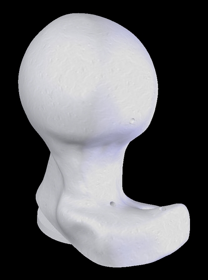
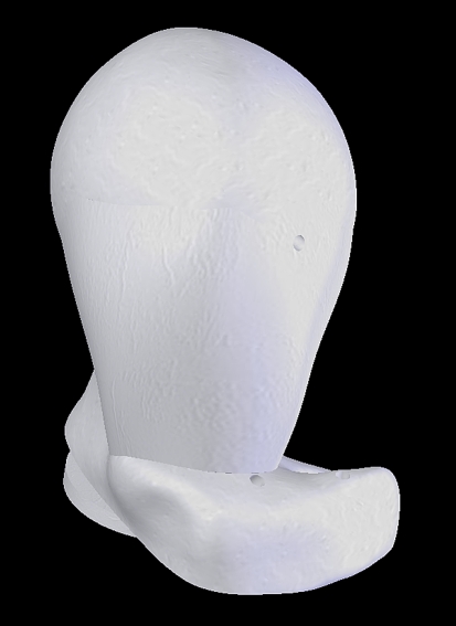
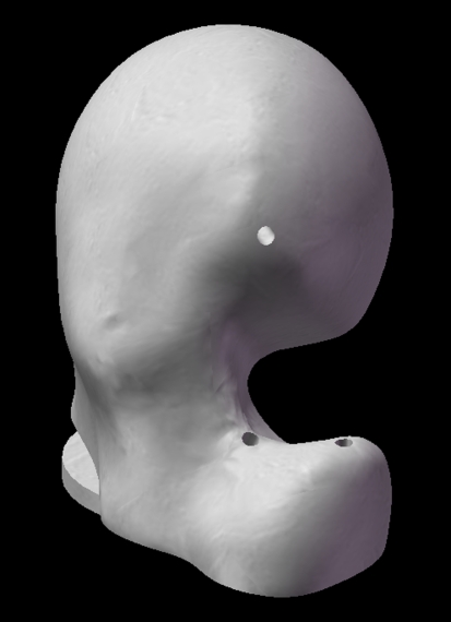
To establish the accuracy of the computed implant-shaft angle, we fitted the phantom leg with various proximal femur components to simulate normal proximal femurs (Fig. 1), geometrically “ideal” proximal femurs (Fig. 2), and two cam-type deformed anatomies; a pistol grip with normal anatomy of the femoral head, but a large exostosis in the anterolateral aspect of the neck and head junction (Fig. 3), and a SCFE with retroversion of the neck and posteroinferior displacement of the articular surface (Fig. 4). The ideal proximal femurs were designed to test the CAS system with geometries conforming to its morphing algorithm, ie, in the experimental settings of the potentially highest accuracy. We reverse engineered the normal and SCFE deformed components from polyurethane bone models (Pacific Research Laboratories Inc, San Diego, CA) with the aid of laser scanners (FARO Laser Scan Arm, FARO Technologies Inc., Lake Mary, FL and LPX-600 3D Laser Scanner, Roland DG Corporation, Hamamatsu-shi, Shizuoka-ken, Japan), reverse engineering software (PolyWorks Version 10.1, InnovMetric Software Inc., Québec, QC, Canada) and computer-aided design (CAD) software (SolidWorks 2007, SolidWorks Corporation, Concord, MA). Both the ideal and pistol grip deformed components were CAD designed. For the latter, we manually added a deformity [9] to the non-deformed model (Pacific Research Laboratories Inc.). All proximal femur components were then printed on an ABS plastic 3-D printer (Dimension Elite, StrataSys, Eden Prairie, MN). The step-by-step procedure of the navigation system relies on the surgeon to pinpoint the medial and lateral epicondyles, femoral neck base lateral, and a sizing point (required for implant positioning and sizing). These landmark points were marked by drilled holes or set screws to ensure their reproducible acquisition throughout this study. We inserted an additional marker (aid point) required for coordinate system calculations along the femoral shaft.
Fig. 1.
A computer-generated image of the head and neck segment with normal bone morphology used for the hip phantom (Pacific Research Laboratories Inc.) is shown.
Fig. 2.
A computer-generated image of the head and neck segment with spherical head and rectangular neck is shown. This model was designed to simulate ideal settings to match with the CAS morphing algorithm.
Fig. 3.
A computer-generated image of the head and neck segment with pistol grip deformity is shown. This model was produced modifying a normal head and neck segment (Pacific Research Laboratories Inc.), adding exuberant bone in the anterolateral region of the head and neck segment. The anatomical orientation of the neck and of the articular surface is identical to the normal morphology model.
Fig. 4.
A computer-generated image of the head and neck segment with SCFE deformity (Pacific Research Laboratories Inc.) is shown. The femoral neck is retroverted and the articular surface of this model is tilted posteriorly and inferiorly.
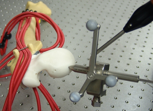
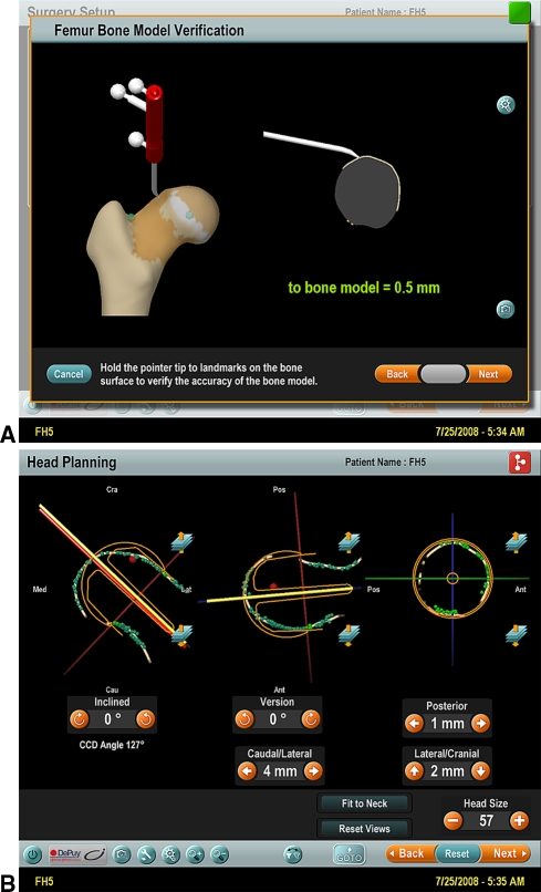
After the assembly of the femur with the required deformity (Fig. 5), we performed the CAS protocol with placement of the guide wire aiming for a CCD angle of 127° (Fig. 6). The arbitrary position of the guide at 127° was solely related to facilitate laboratory settings; in clinical settings, we aim to position the guide in a steeper shaft-neck angle, ie, 135° to 140° degrees [2, 18]. All steps of the CAS procedure were recorded using the integrated software (Fig. 7A–B).
Fig. 5.
A close-up of the phantom hip with pistol grip deformity of the proximal femur before dislocation of the joint and CAS procedure is shown.
Fig. 6.
The experimental set-up showing the phantom femur with SCFE deformity, the guide wire with aiming sleeve, and the CAS infrared probe for measurement of angular position.
Fig. 7A–B.
(A) A screenshot image of the Kolibri CAS system shows verification of accuracy after the morphing protocol. The verification of virtual anatomy accuracy of the CAS model is determined with use of the infrared sensor tool. This is the experimental set-up number 5 of pistol-grip deformity; the verification shows a model accuracy of 0.5 mm. (B) A screenshot image of the Kolibri CAS system after the insertion of the guide wire is shown. The screen shows (1) the CCD angle value of the wire; (2) the angle of wire version in comparison to the “neutral” angle calculated by the CAS algorithm as the angle between the frontal plane (defined by center of the femoral head, center of the femoral neck base lateral, and the midpoint between the two femoral epicondyles) and the lateral plane (defined by the intercondylar line and the axis of the femoral shaft); (3) the superimposed shape of the resurfacing implant; (4) the data depicted in mm represent the deviation of the positioned wire from the “suggested” position calculated by the CAS algorithm.
We recorded both frontal and lateral angles, their offset values after guide wire placement, and the femoral head diameter. Every femur deformity was tested five times, totaling 20 measurements. Assisted drilling, however, was conducted only during the first experiment in each set, and the hole reused for subsequent measurements. We inserted the guide wire hole in the “ideal” proximal femur component into the CAD model, with the trajectory being equidistant from the four faces of the femoral neck and running through the center of the femoral head.
We used a combination of hard- and software tools to assess the navigation system’s accuracy. Stacks of cross-sectional binary images, depicting the guide wire trajectories, were generated for each femoral head component using xray microtomography (SkyScan 1172, SkyScan, Kontich, Belgium), reconstruction (NRecon, SkyScan), and image processing software (CTan, SkyScan). The center and diameter of each femoral head were established using PolyWorks after digitizing the femoral head with a coordinate measuring machine (FARO platinum arm FARO Technologies Inc., Lake Mary, FL). Two data sets of the various femur landmark points were digitized for each femur. The first data set contained the two epicondyles, the aid point and the center of the femoral neck base lateral. The second data set contained the two epicondyles, the aid point, and three points on an alignment guide. The alignment guide was assembled instead of a femoral head component and required to link and align the stack of cross-sectional images. Mathematical computing software (MATLAB, The MathWorks, Natick, MA) was used to process the data sets and images and calculate the implant shaft angle. The combination of microtomography, the digitization of the femoral head center, and the digitization of the two sets of landmark points contributed to an error within our measurement system. By repeating an arbitrary set of measurements, we calculated its intrinsic maximum error to be 0.1° in the frontal plane and 0.4° in the lateral plane.
Results
With normal anatomy we found close agreement between the CAS system and our measurement system: the mean difference of the implant-shaft angle in the frontal plane was 0.7° (confidence intervals [CI] 0.15°–1.17°) (Table 1) and was 0.9° in the lateral plane (CI 0.35°–1.46°) (Table 2). The closest agreement was observed using the “ideal” proximal femur; the mean difference of the implant-shaft angle in the frontal plane was 0.4° (CI 0.1°–1.0°) and was 0.3° in the lateral plane (CI 0.3°–0.8°).
Table 1.
Frontal plane implant-shaft angle evaluation
| Experiment | Initial | Planned | Actual | Calculated | Difference | p-value | Mean | Std Dev | 95% C.I. |
|---|---|---|---|---|---|---|---|---|---|
| NH 1 | 125 | 127 | 125 | 126 | 0.7 | 0.8 | 0.7 | 0.4 | 0.15 and 1.17 |
| NH 2 | 128 | 127 | 126 | 0.3 | |||||
| NH 3 | 129 | 127 | 126 | 0.3 | |||||
| NH 4 | 126 | 127 | 125 | 0.7 | |||||
| NH 5 | 129 | 127 | 127 | 1.3 | |||||
| IH 1 | 123 | 127 | 124 | 123 | 0.9 | 0.3 | 0.4 | 0.4 | −0.14 and 0.98 |
| IH 2 | 123 | 127 | 124 | 0.9 | |||||
| IH 3 | 123 | 127 | 123 | 0.1 | |||||
| IH 4 | 123 | 127 | 123 | 0.1 | |||||
| IH 5 | 123 | 127 | 123 | 0.1 | |||||
| PH 1 | 116 | 127 | 128 | 126 | 1.8 | 0.001 | 1.6 | 0.4 | 1.07 and 2.19 |
| PH 2 | 120 | 127 | 128 | 1.8 | |||||
| PH 3 | 120 | 127 | 127 | 0.8 | |||||
| PH 4 | 117 | 127 | 128 | 1.8 | |||||
| PH 5 | 119 | 127 | 128 | 1.8 | |||||
| SH 1 | 111 | 127 | 127 | 127 | 0.3 | < 0.001 | 0.3 | 0.0 | 0.34 and 0.34 |
| SH 2 | 111 | 127 | 127 | 0.3 | |||||
| SH 3 | 108 | 127 | 127 | 0.3 | |||||
| SH 4 | 109 | 127 | 127 | 0.3 | |||||
| SH 5 | 109 | 127 | 127 | 0.3 |
Table 2.
Lateral plane implant-shaft angle evaluation
| Experiment | Initial | Planned | Actual | Calculated/average | Difference | P value | Mean difference | Standard deviation | 95% C.I. | |
|---|---|---|---|---|---|---|---|---|---|---|
| NH 1 | 0 | 5 | 3 | 3.00 | 3.11 | 0.11 | 0.02 | 0.91 | 0.45 | 0.35 and 1.46 |
| NH 2 | 0 | 5 | 2 | 2.96 | 1.11 | |||||
| NH 3 | 0 | 5 | 2 | 3.20 | 1.11 | |||||
| NH 4 | 0 | 5 | 2 | 3.18 | 1.11 | |||||
| NH 5 | 0 | 5 | 2 | 3.20 | 1.11 | |||||
| IH 1 | 0 | 0 | 1 | −0.06 | −0.06 | 1.06 | 0.25 | 0.26 | 0.45 | −0.29 and 0.82 |
| IH 2 | 0 | 0 | 0 | −0.08 | 0.06 | |||||
| IH 3 | 0 | 0 | 0 | −0.10 | 0.06 | |||||
| IH 4 | 0 | 0 | 0 | −0.02 | 0.06 | |||||
| IH 5 | 0 | 0 | 0 | −0.06 | 0.06 | |||||
| PH 1 | 0 | 0 | −2 | 3.43 | 3.47 | 5.47 | 0.03 | 2.47 | 1.73 | 0.31 and 4.62 |
| PH 2 | 0 | 1 | 2 | 3.45 | 1.47 | |||||
| PH 3 | 0 | 3 | 1 | 3.48 | 2.47 | |||||
| PH 4 | 0 | 3 | 2 | 3.47 | 1.47 | |||||
| PH 5 | 0 | 5 | 2 | 3.50 | 1.47 | |||||
| SH 1 | 0 | −5 | −6 | −7.96 | −7.94 | 1.94 | 0.01 | 2.14 | 1.10 | 0.78 and 3.51 |
| SH 2 | 0 | −5 | −7 | −7.96 | 0.94 | |||||
| SH 3 | 0 | −5 | −4 | −7.91 | 3.94 | |||||
| SH 4 | 0 | −5 | −6 | −7.91 | 1.94 | |||||
| SH 5 | 0 | −5 | −6 | −7.98 | 1.94 | |||||
All values are in degrees.
In the presence of pistol grip deformity, the agreement between CAS and our measurement system deteriorated: the mean difference of the implant-shaft angle in the frontal plane was 1.6° (CI 1.1°–2.2°) and was 2.5° in the lateral plane (CI 0.3°–4.6°). On the other hand, SCFE deformity showed a close agreement in the frontal plane, with a mean difference of the implant-shaft angle of 0.3°, but was only 2.1° in the lateral plane (CI 0.8°–3.5°). Overall, the agreement of implant-shaft angle calculation in the frontal plane was very close in all experimental settings except for the pistol grip deformity. In contrast, on the lateral plane only the “ideal” hip showed close agreement between CAS and our measurement system. Agreement of femoral head size calculation was very close with the “ideal hip” and within 2 mm in the other experimental settings (Table 3).
Table 3.
Femoral head size evaluation
| Experiment | Kolibri® | Calculated/average | Difference | P value | Mean difference | Standard deviation | 95% C.I. | |
|---|---|---|---|---|---|---|---|---|
| NH 1 | 49 | 48.48 | 48.41 | 0.59 | 0.06 | 1.25 | 0.37 | 0.79 and 1.70 |
| NH 2 | 47 | 48.29 | 1.41 | |||||
| NH 3 | 47 | 48.61 | 1.41 | |||||
| NH 4 | 47 | 48.33 | 1.41 | |||||
| NH 5 | 47 | 48.34 | 1.41 | |||||
| IH 1 | 49 | 49.09 | 48.98 | 0.02 | 0.7 | 0.02 | 0.00 | 0.02 |
| IH 2 | 49 | 48.94 | 0.02 | |||||
| IH 3 | 49 | 49.09 | 0.02 | |||||
| IH 4 | 49 | 48.90 | 0.02 | |||||
| IH 5 | 49 | 48.88 | 0.02 | |||||
| PH 1 | 49 | 49.39 | 49.41 | 0.41 | 0.08 | 1.41 | 1.41 | −0.34 and 3.17 |
| PH 2 | 49 | 49.45 | 0.41 | |||||
| PH 3 | 47 | 49.52 | 2.41 | |||||
| PH 4 | 46 | 49.24 | 3.41 | |||||
| PH 5 | 49 | 49.47 | 0.41 | |||||
| SH 1 | 46 | 49.11 | 48.90 | 2.90 | 0.11 | 1.78 | 1.68 | −0.32 and 3.87 |
| SH 2 | 45 | 48.99 | 3.90 | |||||
| SH 3 | 49 | 49.28 | 0.10 | |||||
| SH 4 | 49 | 48.53 | 0.10 | |||||
| SH 5 | 47 | 48.57 | 1.90 | |||||
All values are in mm.
Discussion
CAS is currently utilized to prevent implant malposition in resurfacing of the femoral head, but little is known about its efficacy in the presence of anatomical deformity [5, 18]. We therefore assessed the accuracy of CAS for the navigated positioning of the RHA femoral component in the presence of pistol grip and SCFE anatomical deformities.
This study presents a number of limitations. First, this is an in vitro accuracy assessment; the experimental settings do not take into account several variables like human registration errors of the anatomical landmarks and proximal femur surface, and incorrect execution of the CAS algorithm protocol. In clinical settings, we expect reduced accuracy with larger variations. Second, the Kolibri® system does not report the absolute angle values of head and neck version in the lateral plane. The system indicates to the surgeon the ideal “neutral” positioning of the guide wire passing through the center of the femoral head and along the anatomical axis of the neck in the axial plane. Subsequently, we calculated the version angle values using the coordinates of the basement of the interchangeable proximal femur models in reference to the intercondylar axis. We recognize this is a poor approximation, but we believe this limitation was minimized using fixed anatomical landmarks for the epicondylar region of the femur. We had no access to the algorithm of the CAS system to verify our indirect measurement of version angles. Indeed, in clinical settings the missing information relative to the true version angle can be problematic. On the other hand, the surgeon habitually aims to align the femoral component in the lateral plane according to the patient specific anatomy also in relation to the acetabular version; anatomical correction of abnormal ante- or retroversion of the head and neck segment is usually not indicated in RHA [17]. Third, the validity of surface data points in the presence of a deformity is also a concern. To minimize this concern, we achieved high reproducibility of reference point registration with the pointer array using metal inlays inserted into the sawbone segments and co-planar drill-holes in each of the hinged metal segments. We acknowledge that such experimental optimization may have artificially improved the accuracy figures of the CAS system.
An important distinction should be drawn between precision and accuracy. While precision refers to agreement between repeated measurements, accuracy refers to agreement between measurements and a known true standard [3]. Accuracy of a CAS navigation system can be appropriately evaluated in laboratory settings; clinical trials are usually precision studies [13]. For the purpose of this study, we built a mechanical phantom in conjunction with a precision coordinate measuring system. A similar experimental model was used to assess accuracy of CAS in total knee arthroplasty [17].
There is limited information regarding the accuracy of CAS navigation systems for RHA in the presence of anatomical deformity of the proximal femur. In a previous study, we tested accuracy of a CAS system (Kolibri®, BrainLab) using a head and neck segment with normal anatomical shape but orientated to simulate angular deformities in varus, valgus, anteversion and retroversion [18]. The overall mean measured difference between CAS system and calculated angles in the abnormal anatomy settings was 0.4° in the frontal plane (CI 0.3°–0.5°) and was 2.1° in the lateral plane (CI 1.1°–3.1°).
Recent experimental and clinical studies suggest computer-assisted navigation reduces implant positioning variability in RHA [1, 10–12]. A cadaver study reported a range of error of implant-shaft angle position of 15° (SD 4.2°) with conventional tools and only 8° (SD 2.9°) with CAS technology [7]. In contrast, one clinical trial reported no difference of femoral component position between CAS and conventional RHA surgical procedures [13]. Application of CAS technology in RHA appears independent of surgeon experience [4, 11]. A recent radiographic analysis of a large series of hip resurfacing CAS procedures reported a reduction in the length of the learning curve for beginners and improvement of surgeon’s ability to perform RHA accurately [19]. Our study shows high accuracy of femoral component placement in the frontal plane with CAS, when anatomy of the proximal femur is normal. With the “ideal” proximal femur model we found a potential for improving CAS lateral plane accuracy. With a pistol grip deformity, the accuracy of imageless CAS markedly deteriorates. Accuracy also deteriorates in the presence of SCFE deformity. A recent experimental study reported acceptable accuracy of CAS with pistol-grip deformity models only with the use of CT-based navigation [5]. The pistol grip and the SCFE models we used had marked deformity; we consider deformities of this degree a contraindication for RHA with or without the assistance of computer navigation. Our data suggest CAS technology should not be used to expand the range of utilization of resurfacing surgery, but rather to improve the surgical outcome in cases with suitable anatomy.
Correct positioning of the femoral component in resurfacing hip arthroplasty (RHA) is an important factor in successful long-term outcome [2, 6]. Experimental studies on CAS technology in RHA suggest potential to improve femoral component positioning, but these new tools still require validation in clinical settings. This experimental study shows accurate femoral CAS navigation in RHA using the image-free Kolibri® system in the presence of normal anatomy of the proximal femur. In cases of severe deformity of the proximal femur, the use of this surgical tool appears questionable. This conclusion may not be valid for other CAS systems that use different algorithms. Of note, a recent literature review suggests the best candidates in patient selection for hip resurfacing shall present relatively normal bony morphology [15]. In our surgical practice, we favor conventional total hip replacement for patients with anatomical deformity like the SCFE and FAI models used in this study.
Acknowledgments
We thank Annabel Hayward for assistance during the preparation of the manuscript.
Footnotes
One or more of the authors have received funding from the Wishbone Trust New Zealand (RPP) and from DePuy International, Leeds, UK (RPP).
References
- 1.Barrett AR, Davies BL, Gomes MP, Harris SJ, Henckel J, Jakopec M, Kannan V, Rodriguez y Baena FM, Cobb JP. Computer-assisted hip resurfacing surgery using the acrobot navigation system. Proc Inst Mech Eng [H] 2007;221:773–785. doi: 10.1243/09544119JEIM283. [DOI] [PubMed] [Google Scholar]
- 2.Beaule PE, Lee JL, Le Duff MJ, Amstutz HC, Ebramzadeh E. Orientation of the femoral component in surface arthroplasty of the hip. A biomechanical and clinical analysis. J Bone Joint Surg Am. 2004;86:2015–2021. doi: 10.2106/00004623-200409000-00021. [DOI] [PubMed] [Google Scholar]
- 3.Bragdon CR, Malchau H, Yuan X, Perinchief R, Karrholm J, Borlin N, Estok DM, Harris WH. Experimental assessment of precision and accuracy of radiostereometric analysis for the determination of polyethylene wear in a total hip replacement model. J Orthop Res. 2002;20:688–695. doi: 10.1016/S0736-0266(01)00171-1. [DOI] [PubMed] [Google Scholar]
- 4.Cobb JP, Kannan V, Brust K, Thevendran G. Navigation reduces the learning curve in resurfacing total hip arthroplasty. Clin Orthop Relat Res. 2007;463:90–97. doi: 10.1097/BLO.0b013e318126c0a5. [DOI] [PubMed] [Google Scholar]
- 5.Cobb JP, Kannan V, Dandachli W, Iranpour F, Brust KU, Hart AJ. Learning how to resurface cam-type femoral heads with acceptable accuracy and precision: the role of computed tomography-based navigation. J Bone Joint Surg Am. 2008;90(Suppl 3):57–64. doi: 10.2106/JBJS.H.00606. [DOI] [PubMed] [Google Scholar]
- 6.Daniel J, Pynsent PB, McMinn DJ. Metal-on-metal resurfacing of the hip in patients under the age of 55 years with osteoarthritis. J Bone Joint Surg Br. 2004;86:177–184. doi: 10.1302/0301-620X.86B2.14600. [DOI] [PubMed] [Google Scholar]
- 7.Davis ET, Gallie P, Macgroarty K, Waddell JP, Schemitsch E. The accuracy of image-free computer navigation in the placement of the femoral component of the Birmingham hip resurfacing: A cadaver study. J Bone Joint Surg Br. 2007;89:557–560. doi: 10.1302/0301-620X.89B4.17893. [DOI] [PubMed] [Google Scholar]
- 8.Dorr LD, Hishiki Y, Wan Z, Newton D, Yun A. Development of imageless computer navigation for acetabular component position in total hip replacement. Iowa Orthop J. 2005;25:1–9. [PMC free article] [PubMed] [Google Scholar]
- 9.Ganz R, Parvizi J, Beck M, Leunig M, Notzli H, Siebenrock KA. Femoroacetabular impingement: A cause for osteoarthritis of the hip. Clin Orthop Relat Res. 2003;417:112–120. doi: 10.1097/01.blo.0000096804.78689.c2. [DOI] [PubMed] [Google Scholar]
- 10.Hess T, Gampe T, Kottgen C, Szawlowski B. Intraoperative navigation for hip resurfacing. methods and first results. Orthopade. 2004;33:1183–1193. doi: 10.1007/s00132-004-0693-5. [DOI] [PubMed] [Google Scholar]
- 11.Hodgson A, Helmy N, Masri BA, Greidanus NV, Inkpen KB, Duncan CP, Garbuz DS, Anglin C. Comparative repeatability of guide-pin axis positioning in computer-assisted and manual femoral head resurfacing arthroplasty. Proc Inst Mech Eng [H] 2007;221:713–724. doi: 10.1243/09544119JEIM284. [DOI] [PubMed] [Google Scholar]
- 12.Hodgson AJ, Inkpen KB, Shekhman M, Anglin C, Tonetti J, Masri BA, Duncan CP, Garbuz DS, Greidanus NV. Computer-assisted femoral head resurfacing. Comput Aided Surg. 2005;10:337–343. doi: 10.1080/10929080500379440. [DOI] [PubMed] [Google Scholar]
- 13.Kruger S, Zambelli PY, Leyvraz PF, Jolles BM. Computer-assisted placement technique in hip resurfacing arthroplasty: Improvement in accuracy? Int Orthop. 2007 Aug 24. [Epub ahead of print]. [DOI] [PMC free article] [PubMed]
- 14.Leenders T, Vandevelde D, Mahieu G, Nuyts R. Reduction in variability of acetabular cup abduction using computer assisted surgery: A prospective and randomized study. Comput Aided Surg. 2002;7:99–106. doi: 10.3109/10929080209146021. [DOI] [PubMed] [Google Scholar]
- 15.Nunley RM, Della Valle CJ, Barrack RL. Is patient selection important for hip resurfacing? Clin Orthop Relat Res. 2009;467:56–65. doi: 10.1007/s11999-008-0558-z. [DOI] [PMC free article] [PubMed] [Google Scholar]
- 16.Pitto RP. The trochanter slide osteotomy approach for resurfacing hip arthroplasty. Int Orthop. 2008 May 21. [Epub ahead of print]. [DOI] [PMC free article] [PubMed]
- 17.Pitto RP, Graydon AJ, Bradley L, Malak SF, Walker CG, Anderson IA. Accuracy of a computer-assisted navigation system for total knee replacement. J Bone Joint Surg Br. 2006;88:601–605. doi: 10.1302/0301-620X.88B5.17431. [DOI] [PubMed] [Google Scholar]
- 18.Pitto RP, Malak S, Anderson IA. Accuracy of a computer-assisted navigation system in resurfacing hip arthroplasty. Int Orthop. 2008 Aug 29. [Epub ahead of print]. [DOI] [PMC free article] [PubMed]
- 19.Seyler TM, Lai LP, Sprinkle DI, Ward WG, Jinnah RH. Does computer-assisted surgery improve accuracy and decrease the learning curve in hip resurfacing? A radiographic analysis. J Bone Joint Surg Am. 2008;90(Suppl 3):71–80. doi: 10.2106/JBJS.H.00697. [DOI] [PubMed] [Google Scholar]
- 20.Shimmin AJ, Back D. Femoral neck fractures following birmingham hip resurfacing: A national review of 50 cases. J Bone Joint Surg Br. 2005;87:463–464. doi: 10.1302/0301-620X.87B4.15498. [DOI] [PubMed] [Google Scholar]
- 21.Sikorski JM, Chauhan S. Computer-assisted orthopaedic surgery: Do we need CAOS? J Bone Joint Surg Br. 2003;85:319–323. doi: 10.1302/0301-620X.85B3.14212. [DOI] [PubMed] [Google Scholar]
- 22.Sparmann M, Wolke B, Czupalla H, Banzer D, Zink A. Positioning of total knee arthroplasty with and without navigation support. A prospective, randomised study. J Bone Joint Surg Br. 2003;85:830–835. [PubMed] [Google Scholar]
- 23.Vendittoli PA, Mottard S, Roy AG, Dupont C, Lavigne M. Chromium and cobalt ion release following the durom high carbon content, forged metal-on-metal surface replacement of the hip. J Bone Joint Surg Br. 2007;89:441–448. doi: 10.1302/0301-620X.89B4.18054. [DOI] [PubMed] [Google Scholar]


