Abstract
In computer-assisted TKA, surgeons determine positioning of the femoral component in the sagittal plane based on the sagittal mechanical axis identified by the navigation system. We hypothesized mechanical and distal femoral axes may differ on lateral views and these variations are influenced by anteroposterior bowing and length of the femur. We measured angles between the mechanical axis and distal femoral axis on 200 true lateral radiographs of the whole femur from 100 adults. We used multivariate linear regression to identify predictors of differences between the axes. Depending on the method used to define the two axes, the mean angular difference between the axes was as much as 3.8° and as little as 0.0°, with standard differences ranging from 1.7° to 1.9°. Variation between the two axes increased with increased femoral bowing and increased femoral length. Surgeons should consider differences between the mechanical axes and distal femoral axes when they set the sagittal plane position of a femoral component in navigated cases. Our findings also may be relevant when measuring rotation of the femoral component in the sagittal plane from postoperative radiographs or when interpreting femoral component sagittal rotation results reported in other studies.
Level of Evidence: Level IV, therapeutic study. See the Guidelines for Authors for a complete description of levels of evidence.
Introduction
Sagittal rotation of a femoral component can influence the kinematics of a replaced knee in various ways [11, 22, 25, 35, 38]. If a femoral component is placed in an overly flexed position, it can cause limited extension or polyethylene post wear resulting from impingement between the anterior part of the polyethylene insert and the anterior margin of the intercondylar box in TKA using a post-cam mechanism [23, 25, 28, 38]. When a surgeon places a femoral component in an overly extended position relative to the femur, he or she may create a notch in the anterior femoral cortex, and some fear these notches may increase the prospective risk of a supracondylar fracture [19, 25, 29, 31]. Few studies have explored the clinical implications of femoral component rotation in the sagittal plane. A couple studies have suggested femoral component sagittal rotation could be influenced by the presence of femoral bowing [35, 38].
Numerous studies report use of a computer-assisted navigation system limits the prevalence of outlier values of limb and/or implant alignment measurements in the coronal plane [2, 5, 8, 9, 12, 14, 21, 30, 32, 37]. Whether the same benefits are realized in the sagittal plane when a surgical navigation system is used is unclear [2, 6–8, 12, 18, 32]. One reason is simply that fewer studies have sought to quantify alignment in the sagittal plane. A second is that several methods have been used to define reference axes in the sagittal plane [2, 6–8, 12, 18, 32]. When using a navigation system, a femoral component is placed by referring to the mechanical axis identified by the navigation system [2, 5, 12, 14]. Two different sagittal mechanical axes typically are used by current systems, ie, the line connecting the identified hip center and the registered center of the distal femur, which typically is where an entry point is made for the intramedullary guiding system [2, 5], and the line connecting the femoral head center and the distal femur center identified from kinematically and manually registered points by the navigation system [12, 14]. In contrast, two distal femoral axes frequently are used as references for intraoperative or postoperative assessments of sagittal rotations of femoral components. The distal anterior cortical axis typically is used as an intraoperative reference for correct positioning of a femoral component in the sagittal plane, whereas the distal medullary axis is used as an anatomic reference during postoperative radiographic assessments of sagittal alignment of femoral components [10].
We considered the reported disparities in sagittal rotation of femoral components could be the result of differences between the sagittal mechanical axes used by the navigation system and distal femoral axes used during postoperative radiographic assessments [2, 6–8, 12, 18, 32]. We therefore sought to (1) quantify the sagittal plane angular deviation between the mechanical axis of the femur and its distal femoral axis in the preoperative TKA population, (2) compare the magnitudes of differences between the mechanical and distal femoral axes measures in the right and left femurs of the same patients, and (3) identify variables that predict the magnitude of deviation between the mechanical and distal axes of a femur. We hypothesized (1) meaningful differences do exist, (2) there would be no difference between right and left femurs of the same patients, and (3) the degree of femoral bowing would be the strongest predictor.
Materials and Methods
We performed radiographic measurements in 200 knees of 100 selected patients undergoing TKA for advanced osteoarthritis between July 23, 2007, and May 15, 2008. We excluded patients who had a prior fracture of the femur, congenital anomaly of the femur, or prior knee or hip arthroplasty. Ninety-five patients (190 knees) were women and five (10 knees) were men. The average age of the patients was 68.1 years (range, 57–80 years), and the average body height, weight, and body mass index were 151.8 cm (range, 134.2–174.4 cm), 64.1 kg (range, 41.9–90.8 kg), and 27.8 kg/m2 (range, 20.0–40.2 kg/m2), respectively. This study was approved by the Institutional Review Board of Seoul National University Bundang Hospital, and all patients provided informed consent for use of their radiographs and medical records.
All radiographic measurements were obtained from true lateral radiographs covering the whole femur using PACS working software (Impax™; Agfa, Antwerp, Belgium). We established a new technique for obtaining a true lateral view of the whole femur in which the femoral head is seen clearly and the contours of both femoral condyles are viewed as one line. Patients placed a thigh on a 17-inch × 17-inch digital flat detector (General Diagnostic Radiographic X-Ray System; Philips, Hamburg, Germany) in a diagonal position, and the xray beam tube then was tilted to a 15° cephalad position (Fig. 1). The radiographs were made preoperatively in all patients.
Fig. 1.
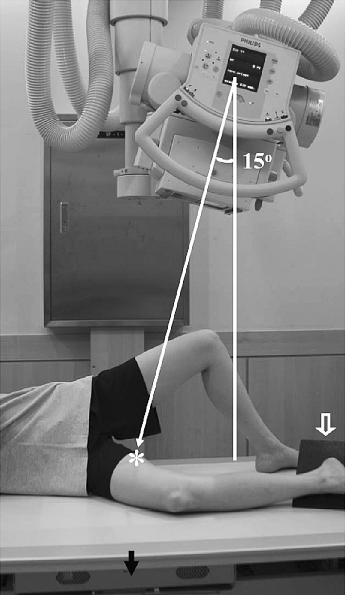
To obtain a true lateral view of the whole femur, patients placed their thigh on a 17-inch × 17-inch digital flat detector in a diagonal position. The xray beam tube was tilted 15° to directly aim the center of the guide beam toward the center of the digital detector (solid arrow) and the midpoint of the patient’s thigh (asterisk). A sponge block (open arrow) was placed to hold the patient’s leg in a right position.
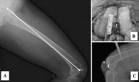
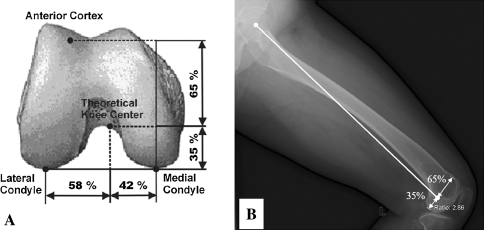
To ensure the sagittal femoral mechanical axes were representative of the axes used by contemporary navigation systems, we defined two sagittal mechanical axes. Mechanical axis 1 was defined as the line connecting the femoral head center to a point 1 cm anterior to the end of Blumensaat’s line (a line extending through the intercondylar notch on a lateral view of the knee) [4, 24], which is used as the registration point for the distal femur center in many navigation systems, including VectorVision® (BrainLAB, Redwood, WA) [7] and the Stryker Navigation System (Stryker Howmedica Osteonics, Allendale, NJ) [32] (Fig. 2) [2, 5]. To validate our definition of mechanical axis 1, we performed a separate study using five knees, in which we checked the position of a pin placed 1 cm anterior to the top of intercondylar notch on a lateral radiograph taken intraoperatively. We found the position of the pin was within 1 mm of the point 1 cm anterior to the end of Blumensaat’s line in all knees. Mechanical axis 2 was defined as the line connecting the femoral head center and a point identified 65% posteriorly on the line between the anterior cortex and the most prominent point of the posterior medial femoral condyle (Fig. 3). We assumed mechanical axis 2 was equivalent to the sagittal mechanical axis used in the OrthoPilot® navigation system (B. Braun-Aesculap, Tuttlingen, Germany) [12, 14, 26]. The angle between mechanical axis 1 and mechanical axis 2 was measured to evaluate the relationship between the two axes.
Fig. 2A–C.
(A) A radiograph shows how mechanical axis 1 was defined. (B) An intraoperative photograph and (C) a radiograph display the registration point (asterisk) for the distal femur center and the top point of the intercondylar notch (solid arrow).
Fig. 3A–B.
(A) A schematic drawing shows how the distal femur center is identified by the OrthoPilot® system. (B) A lateral radiograph shows mechanical axis 2 was defined to represent the point 65% posteriorly in the connecting line between the anterior cortical line and the most prominent point of the posterior femoral condyle.
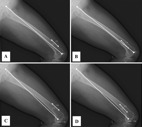
We identified two distal femoral axes. The distal anterior cortex axis was defined as the line connecting two points on the anterior cortex at 5 cm and 10 cm proximal to the knee line and the distal medullary axis connecting midpoints of the outer cortical diameter at 5 cm and 10 cm proximal to the knee line (Fig. 4). With these definitions, we defined the angles between the two distal femoral axes and each of the two sagittal femoral mechanical axes as proxies of the differences. Negative values were assigned to knees in which the anatomic reference was oriented in an extended position (recurvatum) with reference to the sagittal mechanical axes.
Fig. 4A–D.
The radiographic measurements of the differences are shown between (A) mechanical axis 1 versus the distal anterior cortex axis, (B) mechanical axis 1 versus the distal medullary axis, (C) mechanical axis 2 versus the distal anterior cortex axis, and (D) mechanical axis 2 versus the distal medullary axis.
To assess the reliability of measurements using the references mentioned, two orthopaedic surgeons (CBJ, KTK) and one clinical investigator (KYG) performed measurements twice with a 1-week interval in 20 patients (40 knees), which were randomly selected from among the 100 patients. The degree of measurement reliabilities was assessed using intraclass correlation coefficients. The intraclass correlation coefficient for intrarater and interrater agreement was greater than 0.86 for all measurements. These findings allowed us to rely on the validities of measurements using the references and measurement data produced by one investigator (CBJ).
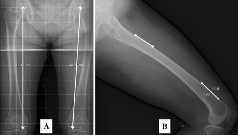
To obtain anthropometric femoral dimensions, femur length and degree of femoral bowing were measured (Fig. 5). Femur lengths were measured using long cassette radiographs with grids covering the entire lower limb, which we considered less sensitive to magnification variation than the lateral radiographs. Degrees of femoral bowing were assessed using the angle between the anterior cortical lines of the proximal and distal femur. Proximal anterior cortical lines were drawn as the line connecting the two points 10 cm and 15 cm distal to the proximal end of femoral head and distal anterior cortical lines as the line connecting the two points 5 cm and 10 cm proximal to the distal end of the medial femoral condyle.
Fig. 5A–B.
(A) The femur length was measured on long cassette AP radiographs using grids, and (B) the degrees of bowing were determined by measuring the angle between the anterior cortical line and the proximal cortical line.
All data were summarized as means, standard differences, and ranges. We calculated the proportion of knees with a deviation greater than 2°, which we assumed to be clinically important considering the navigation system has an accuracy of ± 1° [27] and our radiographic measurements would have 1° variation. The Kolmogorov-Smirnov test was used to confirm measured data followed a normal (Gaussian-shaped) distribution. To determine whether both knees of a patient had similar patterns, measured angles for right and left knees of the same patient were compared, and the differences between right and left knees were determined using the paired-sample t test. To identify predictors of differences between sagittal femoral mechanical axes and distal femoral axes, stepwise multiple linear regression analyses were performed for demographic factors (gender, age, laterality [right or left], body height, weight, body mass index) and anthropometric femoral dimensions (femur length, femoral bowing angle). A priori power analyses were performed to confirm the study sample size had a power greater than 99% to detect a difference of 1° from laterality (right knees versus left knees) with an alpha level of 0.05. The analyses were performed using the SPSS® for Windows® statistical package (Version 12.0; SPSS Inc, Chicago, IL).
Results
Notable differences sometimes were observed between distal femoral axes and the sagittal femoral mechanical axes (Table 1). On average, the distal anterior cortex axis and distal medullary axis were in a flexed position with respect to mechanical axis 1 by 3.0° and 3.8°, respectively, whereas they were in a position almost parallel to mechanical axis 2 by 0° and 0.9°, respectively. The mean angle between mechanical axis 1 and mechanical axis 2 was 3° (standard deviation, 0.3; range, 1°–5°), indicating mechanical axis 2 was oriented in the flexion position to mechanical axis 1 in all knees. Mechanical axis 1 differed by as much as 8.5° from either of the two distal femoral axes, whereas mechanical axis 2 differed by as much as 5.6° from either of the two distal axes. Greater than 20% of the 200 knees had a deviation greater than 2° from the mean value.
Table 1.
Summary of the measured parameters
| Parameter | Mean* | Range | Number of knees with a deviation > 2° from the mean value |
|---|---|---|---|
| Angle between distal femoral anterior cortex axis and MA1 | 3.0° (1.9°) | −1.0°–8.5° | 61 (30.5%) |
| Angle between distal medullary axis and MA1 | 3.8° (1.7°) | −0.4°–8.5° | 47 (23.5%) |
| Angle between distal femoral anterior cortex axis and MA2 | 0.0° (1.9°) | −4.4°–5.5° | 61 (30.5%) |
| Angle between distal medullary axis and MA2 | 0.9° (1.7°) | −3.7°–5.6° | 43 (21.5%) |
* Data are given as means, with standard deviations in parentheses; MA1 = mechanical axis 1; MA2 = mechanical axis 2.
No differences were detected when the differences between the mechanical and distal femoral axes of the right and left knees of the same patients were compared (Table 2). However, in greater than 5% (range, 6%–10%) of the patients, the absolute difference of the deviation between the mechanical axis and distal femoral axis of the two knees was greater than 2°.
Table 2.
Comparisons of right and left knees in the same patient
| Parameter | Right* (n = 100) | Left* (n = 100) | p Value | Difference between right and left knees | ||
|---|---|---|---|---|---|---|
| Mean* | Range | > 2° | ||||
| Angle between distal anterior cortex axis and MA1 | 2.9° (1.9°) | 3.0° (1.8°) | 0.675 | 0.9° (0.7°) | −2.9°–3.1° | 6% |
| Angle between distal medullary axis and MA1 | 3.7° (1.7°) | 3.9° (1.7°) | 0.484 | 1.0° (0.8°) | −2.6°–4.4° | 10% |
| Angle between distal anterior cortex axis and MA2 | −0.02° (2.0°) | 0.1° (1.9°) | 0.751 | 0.9° (0.7°) | −3.1°–3.1° | 7% |
| Angle between distal medullary axis and MA2 | 0.8° (1.7°) | 0.9° (1.7°) | 0.648 | 1.1° (1.0°) | −2.7°–6.7° | 10% |
* Data are given as means, with standard deviations in parentheses; MA1 = mechanical axis 1; MA2 = mechanical axis 2.
The degree of femoral bowing and femur length predicted differences between the sagittal femoral mechanical axes and the distal femoral axes. The degree of femoral bowing was the strongest predictor of differences followed by femoral length (Table 3). The major portion (ΔR2, 51.9%–73.8%) of the differences was explained by the degree of femoral bowing, and the femur length explained the minor portion (ΔR2, 5.3%–7.1%). For each 1° of femoral bowing or 1 cm of femur length, the deviation between the distal femoral axis and mechanical axis increased by 0.38° to 0.47° or by 0.17° to 0.32°, respectively. The deviation between the mechanical axis and the distal femoral axis was not associated with the other studied factors (age, gender, height, weight, body mass index, knee laterality).
Table 3.
Results of the multiple regression analyses*
| Parameter | Factors† | B | SE (B) | β | p Value | ΔR2 |
|---|---|---|---|---|---|---|
| Angle between distal anterior cortex axis and MA1 | Femur bowing angle | 0.47 | 0.02 | 0.85 | < 0.001 | 73.8 |
| Femur length | 0.17 | 0.03 | 0.23 | < 0.001 | 5.3 | |
| Angle between distal medullary axis and MA1 | Femur bowing angle | 0.41 | 0.03 | 0.78 | < 0.001 | 62.3 |
| Femur length | 0.18 | 0.04 | 0.26 | < 0.001 | 6.2 | |
| Angle between distal anterior cortex axis and MA2 | Femur bowing angle | 0.47 | 0.02 | 0.83 | < 0.001 | 51.9 |
| Femur length | 0.32 | 0.06 | 0.42 | < 0.001 | 7.1 | |
| Angle between distal medullary axis and MA2 | Femur bowing angle | 0.38 | 0.03 | 0.73 | < 0.001 | 54.5 |
| Femur length | 0.18 | 0.04 | 0.26 | < 0.001 | 5.8 |
* The regression equation from the multivariate model is [constant + B value x femur bowing angle (degrees) + B value x femur length (cm)], where constant = −9.89 for the angle between distal anterior cortex axis and MA1, −11.21 for the angle between distal medullary axis and MA1, −12.22 for the angle between the distal anterior cortex axis and MA2, and −13.9 for the angle between distal medullary axis and MA2; †selected from the eight patient factors (gender, age, laterality, body height, weight, body mass index, femur length, femur bowing angle) in the model by multiple linear regression analysis with stepwise variable exclusion with p > 0.05; MA1 = mechanical axis 1; MA2 = mechanical axis 2; B = regression coefficient; SE (B) = standard error of B; β = standardized regression coefficient; ΔR2 = percent variance explained by each variable.
Discussion
In performing TKA with a computer-assisted navigation system, sagittal mechanical axes identified by the navigation system play a key role as the reference to determine positioning of the femoral component in the sagittal plane. Information on the relationship between the sagittal mechanical axis and distal femoral axes is important for intraoperative evaluations or postoperative radiographic assessments of femoral component sagittal rotation, which can influence the kinematics of a replaced knee [22, 25, 35, 38]. Current navigation systems typically provide a default target value for positioning the femoral component in the sagittal plane using the reference sagittal mechanical axis identified by the system. Target sagittal alignments intended in previous studies that have used a navigation system vary widely from 0° to 5°, but fixed values were used and individual variations were not considered (Table 4) [2, 3, 7, 12, 18, 21, 33]. We therefore sought to (1) quantify the sagittal plane angular deviation between the mechanical axis of the femur and its distal femoral axis in a preoperative TKA population, (2) compare the magnitudes of differences between the mechanical and distal femoral axes measures in the right and left femurs of the same patients, and (3) identify variables that predict the magnitude of deviation between the mechanical and distal axes of a femur.
Table 4.
Summary of the studies
| Study (year) | Study design and navigation system* | Surgical reference | Radiographic reference | Outcome in sagittal alignment |
|---|---|---|---|---|
| Sparmann et al. [32] (2003) | Conventional 120 versus navigated 120 Stryker Navigation System | No information | No information on the reference | Better in navigated group (optimal position: conventional 22% versus navigated 80%, p < 0.001) |
| Bathis et al. [2] (2004) | Conventional 80 versus navigated 80 VectorVision | Anterior cortical surface with additional flexion of 5° | Anterior cortex and the shield of femoral component | Better in navigated group (lateral femoral angle: conventional 9.5° versus 7.3°, p < 0.001) |
| Chauhan et al. [5] (2004) | Conventional 35 versus Navigated 35 Stryker navigation system | No information | No information on the reference | No difference (p = 0.425) |
| Victor and Hoste [37] (2004) | Conventional 50 versus navigated 50 Fluoroscopy-based iON | No information | Posterior cortical line | No difference (conventional 2.4° versus navigated 2.9°, p = 0.19) |
| Anderson et al. [1] (2005) | Conventional 51 versus navigated 116 Stryker Navigation System | No information | No information | Better in navigated (conventional 0.4° extension versus navigated 0.8° flexion, p < 0.02) |
| Chin et al. [7] (2005) | Conventional 30 versus navigated 30 VectorVision | 0°–3° flexion to sagittal mechanical axis | Connecting line between hip center and knee center (not specified) | Better in navigated (conventional 3.9° versus navigated 0.9°, p = 0.005) |
| Haaker et al. [12] (2005) | Conventional 100 versus navigated 100 OrthoPilot | Perpendicular to sagittal mechanical axis | Anterior cortical line versus perpendicular line of distal part of femoral condyle | Better in navigated group (88.5° versus 89.4°, p < 0.001) |
| Jenny et al. [14] (2005) | Conventional 235 versus navigated 235 OrthoPilot | 90° between anterior cortical line and horizontal axis of femoral component | Sagittal mechanical axis (not specified) | Better in navigated (conventional 88.6° versus navigated 89.2°, p = 0.005; optimal: conventional 71% versus navigated 80%, p = 0.02) |
| Ensini et al. [9] (2007) | Conventional 60 versus navigated 60 Stryker Navigation System | 0° to the sagittal mechanical axis | Longitudinal axis of the femur shaft | Better in navigated group (mean: conventional 6.2° versus navigated 3.6°, p < 0.001; outlier: conventional 50% versus navigated 27%, p = 0.019) |
| Kim et al. [18] (2007) | Conventional 100 versus navigated 100 VectorVision | Anterior cortical plane with additional flexion of 5° | Anterior cortical line | No difference (outlier: conventional 31% versus navigated 33%, p = 0.822) |
| Matziolis et al. [21] (2007) | Conventional 28 versus navigated 32 PiGalileo system | Parallel to anterior cortical surface | Sagittal mechanical axis by computer tomography | No difference |
| Dutton et al. [8] (2008) | Conventional 54 versus navigated 54 Ci TKA system | No information | Sagittal mechanical axis (not specified) | Better in navigated group for the mean (conventional 6.2° versus navigated 3.6°, p < 0.001), but no difference in prevalence of outliers (conventional 86% versus 79%, p = 0.48) |
| Rosenberger et al. [30] (2008) | Conventional 50 versus navigated 50 Treon plus | No information | Anterior cortical line | No difference in the mean but less outlier in navigated |
| Tingart et al. [36] (2008) | Conventional 500 versus navigated 500 VectorVision and Ci system | No information | Anterior cortical line | Better in navigated (conventional 10.3° versus navigated 5.9°, p < 0.01) |
* Navigation systems included: Stryker Navigation System (Stryker Howmedica Osteonics, Allendale, NJ); VectorVision® (BrainLAB, Redwood, CA); fluoroscopy-based iON® (Medtronic, Louisville, KY); OrthoPilot® (B. Braun-Aesculap, Tuttlingen, Germany); PiGalileo® system (Plus Orthopedics AG, Rotkreuz, Switzerland); Ci® TKA system (DePuy/BrainLab, Munich, Germany); Treon™ plus (Medtronic, Minneapolis, MN); Ci® system (Iorthopedics, Munich, Germany).
Several limitations should be noted when considering our findings. First, anatomic features of the femur may depend on ethnicity. All subjects enrolled in the current study were ethnically Korean, and thus, it may not be possible to directly extrapolate our results to other ethnicities. Second, the majority of our patients were women (only 10 men were included), which limits the statistical power of our study to detect subtle differences by gender. However, this study was conducted in a consecutive series, and the gender proportion of our study population is similar to other TKA series reported from Korea [15–17]. Finally, despite our efforts to obtain radiographs of suitable quality, our study is inherently limited by the use of plain radiographs, eg, by issues such as magnification, limb positional variances, and inability to assess three-dimensional features [20, 34]. In addition, we assumed the point 1 cm anterior to the end of Blumensaat’s line represents a typical registration point for the distal femur center, but the position of this registration point depends on technique.
Our findings show substantial differences do exist between the sagittal femoral mechanical axes and distal femoral axes. Mechanical axis 1 differed by as much as 8.5° from either of the two distal femoral axes, whereas mechanical axis 2 differed by as much as 5.6° from either of the two distal axes (Table 1). Greater than 20% of the 200 knees had a deviation greater than 2° from the mean value. Our findings have several clinical implications in applying the navigation technology to TKA. First, observed average deviation values can be used to modify a default target value if the target value intends to position the femoral component with reference to the distal femoral axes. Second, if surgeons want to set the sagittal femoral component rotation with reference to the distal femoral axes, different target values for sagittal femoral component rotation should be applied when using different navigation systems that identify a different sagittal mechanical axis. We found the mean angle between mechanical axis 1 and mechanical axis 2 was 3°, and mechanical axis 2 had smaller differences from the distal femoral axes than mechanical axis 1. However, our findings do not advocate a specific system because there are no documented ideal target values, and surgeons can adjust the target values with the relevant information of the navigation system being used. Third, our findings may explain why the sagittal alignments of femoral components in TKA performed using navigation technology, which relies on the sagittal femoral mechanical axis, vary as determined by postoperative radiographic assessments in a manner that depends on the distal femoral axes.
Intuitively, it might be expected the two femurs of an individual have identical anthropometric features, and thus, we assumed both femurs would yield identical results, and as was expected, we found no major differences between right and left knees in terms of the mean values of differences between the mechanical and the distal femoral axes (Table 2). In contrast, it also would be expected there are tendencies for the right femur to have larger or smaller differences than the left femur, but we found the right and left femurs of the same patient tended to have similar differences between the mechanical and distal femoral axes in the majority (90% or more). However, knees with a deviation greater than 2° sometimes were seen (6%–10%), which may suggest optimization on a knee-by-knee basis is a better option if surgeons prefer to determine sagittal femoral component rotation with reference to distal femoral axes.
We found the degree of femoral bowing to be the strongest predictor of differences between the sagittal mechanical axes and the distal femoral axes. For each 1° of anterior femoral bowing, the angular deviation between the mechanical and distal femoral axes increased nearly 0.5°. Previous studies have reported the existence of anterior femoral bowing [11, 13, 35]. Because of differences in the methods used to evaluate femoral bowing, direct comparisons are difficult, but our study confirms the existence of anterior femoral bowing in Korean patients. Femoral length was the only other studied factor associated with the angular deviation between the mechanical axis and distal femoral axis; a 1-cm increase in femoral length would be associated with an approximately 0.25° increase in the deviation between the mechanical axis and distal femoral axis. Furthermore, based on our results, it seems most important to consider the consequences of using a mechanical axis as an intraoperative reference (as is commonly the case in computer-assisted surgery), a distal femoral axis as an intraoperative reference (as is commonly the case in non-computer-assisted surgery), or a distal femoral axis as a postoperative radiographic reference when the femur is more anteriorly bowed or is longer.
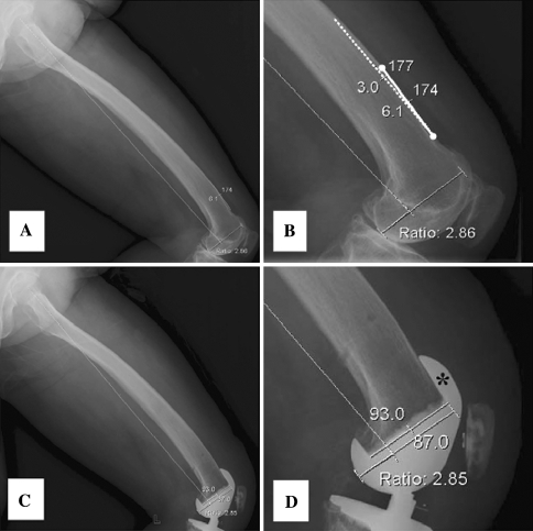
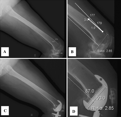
Our data suggest the mechanical and distal femoral axes may differ by as much as 6° to 9° in the sagittal plane, depending on the measurement method used, and identify anterior bowing as the best predictor of such differences. This study suggests, when using navigation technology in TKA, surgeons should consider these differences between sagittal femoral mechanical axes and distal femoral axes, especially if the femur is bowed anteriorly. This is especially important for surgeons who prefer to customize the sagittal flexion angle of the femoral component such that its anterior flange is nearly parallel to the anterior cortex of the femur (Figs. 6, 7). Our findings also may be relevant when measuring rotation of the femoral component in the sagittal plane from postoperative radiographs or when interpreting femoral component sagittal rotation results reported in other studies.
Fig. 6A–D.
(A) A preoperative radiographic assessment of a patient shows the anterior cortical line is oriented in a position of 6° flexion relative to the mechanical axis 2. (B) Projected into the anterior cortex are the line (dotted line) oriented in the position of 3° flexion reflecting the design feature of 3° flexion in the anterior flange of a femoral component. (C) A postoperative radiograph shows distal femur resection was performed at an angle of 3° flexion relative to the mechanical axis 2. (D) The anterior flange of the femoral component (asterisk) sits perfectly on the anterior cortical surface without anterior notching or anterior flange prominence.
Fig. 7A–D.
(A) A preoperative radiographic assessment of a patient shows the anterior cortical line is oriented in a position of 1° extension with respect to the mechanical axis 2. (B) Projected off the anterior cortex is the line (dotted line) oriented in the position of 3° reflecting the design feature of 3° flexion in the anterior flange of a femoral component. (C) A postoperative radiograph shows distal femur resection was performed at an angle of 3° extension relative to the mechanical axis 2. (D) The anterior flange of the femoral component (asterisk) sits perfectly on the anterior cortical surface without anterior notching or anterior flange prominence.
Acknowledgments
We thank Dr Sae Kwang Kwon (Yeonsei Sarang Hospital, Seoul, Korea) and Professor Jae Ho Yoo (Sunchonhyang University Hospital, Bucheon, Korea) for participation in scientific discussion to design and perform this study.
Footnotes
One or more of the authors (TKK) have received funding from the clinical research fund (B-0704/044-013) of Seoul National University Bundang Hospital.
Each author certifies that his or her institution has approved the human protocol for this investigation, that all investigations were conducted in conformity with ethical principles of research, and that informed consent was obtained.
This work was performed at Seoul National University Bundang Hospital.
References
- 1.Anderson KC, Buehler KC, Markel DC. Computer assisted navigation in total knee arthroplasty: comparison with conventional methods. J Arthroplasty. 2005;20:132–138. doi: 10.1016/j.arth.2005.05.009. [DOI] [PubMed] [Google Scholar]
- 2.Bathis H, Perlick L, Tingart M, Luring C, Zurakowski D, Grifka J. Alignment in total knee arthroplasty: a comparison of computer-assisted surgery with the conventional technique. J Bone Joint Surg Br. 2004;86:682–687. doi: 10.1302/0301-620X.86B5.14927. [DOI] [PubMed] [Google Scholar]
- 3.Bolognesi M, Hofmann A. Computer navigation versus standard instrumentation for TKA: a single-surgeon experience. Clin Orthop Relat Res. 2005;440:162–169. doi: 10.1097/01.blo.0000186561.70566.95. [DOI] [PubMed] [Google Scholar]
- 4.Brattstrom H. Patella alta in non-dislocating knee joints. Acta Orthop Scand. 1970;41:578–588. doi: 10.3109/17453677008991549. [DOI] [PubMed] [Google Scholar]
- 5.Chauhan SK, Scott RG, Breidahl W. Beaver RJ: Computer-assisted knee arthroplasty versus a conventional jig-based technique: a randomised, prospective trial. J Bone Joint Surg Br. 2004;86:372–377. doi: 10.1302/0301-620X.86B3.14643. [DOI] [PubMed] [Google Scholar]
- 6.Chin PL, Foo LS, Yang KY, Yeo SJ, Lo NN. Randomized controlled trial comparing the radiologic outcomes of conventional and minimally invasive techniques for total knee arthroplasty. J Arthroplasty. 2007;22:800–806. doi: 10.1016/j.arth.2006.10.009. [DOI] [PubMed] [Google Scholar]
- 7.Chin PL, Yang KY, Yeo SJ, Lo NN. Randomized control trial comparing radiographic total knee arthroplasty implant placement using computer navigation versus conventional technique. J Arthroplasty. 2005;20:618–626. doi: 10.1016/j.arth.2005.04.004. [DOI] [PubMed] [Google Scholar]
- 8.Dutton AQ, Yeo SJ, Yang KY, Lo NN, Chia KU, Chong HC. Computer-assisted minimally invasive total knee arthroplasty compared with standard total knee arthroplasty: a prospective, randomized study. J Bone Joint Surg Am. 2008;90:2–9. doi: 10.2106/JBJS.F.01148. [DOI] [PubMed] [Google Scholar]
- 9.Ensini A, Catani F, Leardini A, Romagnoli M, Giannini S. Alignments and clinical results in conventional and navigated total knee arthroplasty. Clin Orthop Relat Res. 2007;457:156–162. doi: 10.1097/BLO.0b013e3180316c92. [DOI] [PubMed] [Google Scholar]
- 10.Ewald FC. The Knee Society total knee arthroplasty roentgenographic evaluation and scoring system. Clin Orthop Relat Res. 1989;248:9–12. [PubMed] [Google Scholar]
- 11.Gilbert BM. Anterior femoral curvature: its probable basis and utility as a criterion of racial assessment. Am J Phys Anthropol. 1976;45:601–604. doi: 10.1002/ajpa.1330450326. [DOI] [PubMed] [Google Scholar]
- 12.Haaker RG, Stockheim M, Kamp M, Proff G, Breitenfelder J, Ottersbach A. Computer-assisted navigation increases precision of component placement in total knee arthroplasty. Clin Orthop Relat Res. 2005;454:152–159. doi: 10.1097/01.blo.0000150564.31880.c4. [DOI] [PubMed] [Google Scholar]
- 13.Harper MC, Carson WL. Curvature of the femur and the proximal entry point for an intramedullary rod. Clin Orthop Relat Res. 1987;220:155–161. [PubMed] [Google Scholar]
- 14.Jenny JY, Clemens U, Kohler S, Kiefer H, Konermann W, Miehlke RK. Consistency of implantation of a total knee arthroplasty with a non-image-based navigation system: a case-control study of 235 cases compared with 235 conventionally implanted prostheses. J Arthroplasty. 2005;20:832–839. doi: 10.1016/j.arth.2005.02.002. [DOI] [PubMed] [Google Scholar]
- 15.Kim TH, Lee DH, Bin SI. The NexGen LPS-flex to the knee prosthesis at a minimum of three years. J Bone Joint Surg Br. 2008;90:1304–1310. doi: 10.1302/0301-620X.90B10.21050. [DOI] [PubMed] [Google Scholar]
- 16.Kim TK, Chung BJ, Kang YG, Chang CB, Seong SC. Clinical implications of anthropometric patellar dimensions for TKA in Asians. Clin Orthop Relat Res. 2008 Oct 15. [Epub ahead of print]. [DOI] [PMC free article] [PubMed]
- 17.Kim YH, Kim JS, Hong KS, Kim YJ, Kim JH. Prevalence of fat embolism after total knee arthroplasty performed with or without computer navigation. J Bone Joint Surg Am. 2008;90:123–128. doi: 10.2106/JBJS.G.00176. [DOI] [PubMed] [Google Scholar]
- 18.Kim YH, Kim JS, Yoon SH. Alignment and orientation of the components in total knee replacement with and without navigation support: a prospective, randomised study. J Bone Joint Surg Br. 2007;89:471–476. doi: 10.1302/0301-620X.89B4.18878. [DOI] [PubMed] [Google Scholar]
- 19.Lesh ML, Schneider DJ, Deol G, Davis B, Jacobs CR, Pellegrini VD., Jr The consequences of anterior femoral notching in total knee arthroplasty: a biomechanical study. J Bone Joint Surg Am. 2000;82:1096–1101. doi: 10.2106/00004623-200008000-00005. [DOI] [PubMed] [Google Scholar]
- 20.Lonner JH, Laird MT, Stuchin SA. Effect of rotation and knee flexion on radiographic alignment in total knee arthroplasties. Clin Orthop Relat Res. 1996;331:102–106. doi: 10.1097/00003086-199610000-00014. [DOI] [PubMed] [Google Scholar]
- 21.Matziolis G, Krocker D, Weiss U, Tohtz S, Perka C. A prospective, randomized study of computer-assisted and conventional total knee arthroplasty: three-dimensional evaluation of implant alignment and rotation. J Bone Joint Surg Am. 2007;89:236–243. doi: 10.2106/JBJS.F.00386. [DOI] [PubMed] [Google Scholar]
- 22.Mihalko WM, Boyle J, Clark LD, Krackow KA. The variability of intramedullary alignment of the femoral component during total knee arthroplasty. J Arthroplasty. 2005;20:25–28. doi: 10.1016/j.arth.2004.10.011. [DOI] [PubMed] [Google Scholar]
- 23.O’Rourke MR, Callaghan JJ, Goetz DD, Sullivan PM, Johnston RC. Osteolysis associated with a cemented modular posterior-cruciate-substituting total knee design: five to eight-year follow-up. J Bone Joint Surg Am. 2002;84:1362–1371. doi: 10.2106/00004623-200208000-00011. [DOI] [PubMed] [Google Scholar]
- 24.Phillips BB. Recurrent dislocations. In: Canale ST, editor. Campbell’s Operative Orthopaedics. Philadelphia, PA: Mosby; 2003. pp. 2377–2448. [Google Scholar]
- 25.Piazza SJ, Delp SL, Stulberg SD, Stern SH. Posterior tilting of the tibial component decreases femoral rollback in posterior-substituting knee replacement: a computer simulation study. J Orthop Res. 1998;16:264–270. doi: 10.1002/jor.1100160214. [DOI] [PubMed] [Google Scholar]
- 26.Picard F. (2007) Computer Assisted Orthopaedics: The Image Free Concept. Berlin, Germany: Pro BUSINESS GmbH; 375.
- 27.Pitto RP, Graydon AJ, Bradley L, Malak SF, Walker CG, Anderson IA. Accuracy of a computer-assisted navigation system for total knee replacement. J Bone Joint Surg Br. 2006;88:601–605. doi: 10.1302/0301-620X.88B5.17431. [DOI] [PubMed] [Google Scholar]
- 28.Puloski SK, McCalden RW, MacDonald SJ, Rorabeck CH, Bourne RB. Tibial post wear in posterior stabilized total knee arthroplasty: an unrecognized source of polyethylene debris. J Bone Joint Surg Am. 2001;83:390–397. doi: 10.2106/00004623-200103000-00011. [DOI] [PubMed] [Google Scholar]
- 29.Ritter MA, Thong AE, Keating EM, Faris PM, Meding JB, Berend ME, Pierson JL, Davis KE. The effect of femoral notching during total knee arthroplasty on the prevalence of postoperative femoral fractures and on clinical outcome. J Bone Joint Surg Am. 2005;87:2411–2414. doi: 10.2106/JBJS.D.02468. [DOI] [PubMed] [Google Scholar]
- 30.Rosenberger RE, Hoser C, Quirbach S, Attal R, Hennerbichler A, Fink C. Improved accuracy of component alignment with the implementation of image-free navigation in total knee arthroplasty. Knee Surg Sports Traumatol Arthrosc. 2008;16:249–257. doi: 10.1007/s00167-007-0420-y. [DOI] [PubMed] [Google Scholar]
- 31.Shawen SB, Belmont PJ, Jr, Klemme WR, Topoleski LD, Xenos JS, Orchowski JR. Osteoporosis and anterior femoral notching in periprosthetic supracondylar femoral fractures: a biomechanical analysis. J Bone Joint Surg Am. 2003;85:115–121. doi: 10.1302/0301-620X.85B1.13212. [DOI] [PubMed] [Google Scholar]
- 32.Sparmann M, Wolke B, Czupalla H, Banzer D, Zink A. Positioning of total knee arthroplasty with and without navigation support: a prospective, randomised study. J Bone Joint Surg Br. 2003;85:830–835. [PubMed] [Google Scholar]
- 33.Stulberg SD. How accurate is current TKR instrumentation? Clin Orthop Relat Res. 2003;416:177–184. doi: 10.1097/01.blo.0000093029.56370.0f. [DOI] [PubMed] [Google Scholar]
- 34.Swanson KE, Stocks GW, Warren PD, Hazel MR, Janssen HF. Does axial limb rotation affect the alignment measurements in deformed limbs? Clin Orthop Relat Res. 2000;371:246–252. doi: 10.1097/00003086-200002000-00029. [DOI] [PubMed] [Google Scholar]
- 35.Tang WM, Chiu KY, Kwan MF, Ng TP, Yau WP. Sagittal bowing of the distal femur in Chinese patients who require total knee arthroplasty. J Orthop Res. 2005;23:41–45. doi: 10.1016/j.orthres.2004.06.013. [DOI] [PubMed] [Google Scholar]
- 36.Tingart M, Luring C, Bathis H, Beckmann J, Grifka J, Perlick L. Computer-assisted total knee arthroplasty versus the conventional technique: how precise is navigation in clinical routine? Knee Surg Sports Traumatol Arthrosc. 2008;16:44–50. doi: 10.1007/s00167-007-0399-4. [DOI] [PubMed] [Google Scholar]
- 37.Victor J, Hoste D. Image-based computer-assisted total knee arthroplasty leads to lower variability in coronal alignment. Clin Orthop Relat Res. 2004;428:131–139. doi: 10.1097/01.blo.0000147710.69612.76. [DOI] [PubMed] [Google Scholar]
- 38.Yehyawi TM, Callaghan JJ, Pedersen DR, O’Rourke MR, Liu SS. Variances in sagittal femoral shaft bowing in patients undergoing TKA. Clin Orthop Relat Res. 2007;464:99–104. doi: 10.1097/BLO.0b013e318157e4a2. [DOI] [PubMed] [Google Scholar]


