Abstract
Background
We developed a cardiac SPECT system (X-ACT) with low dose volume CT transmission-based attenuation correction (AC). Three solid-state detectors are configured to form a triple-head system for emission scans and reconfigured to form a 69-cm field-of-view detector arc for transmission scans. A near mono-energetic transmission line source is produced from the collimated fluorescence x-ray emitted from a lead target when the target is illuminated by a narrow polychromatic x-ray beam from an x-ray tube. Transmission scans can be completed in 1 min with insignificant patient dose (deep dose equivalent <5 μSv).
Methods
We used phantom studies to evaluate (1) the accuracy of the reconstructed attenuation maps, (2) the effect of AC on image uniformity, and (3) the effect of AC on defect contrast (DC). The phantoms we used included an ACR phantom, an anthropomorphic phantom with a uniform cardiac insert, and an anthropomorphic phantom with two defects in the cardiac insert.
Results
The reconstructed attenuation coefficient of water at 140 keV was .150 ± .003/cm in the uniform region of the ACR phantom, .151 ± .003/cm and .151 ± .002/cm in the liver and cardiac regions of the anthropomorphic phantom. The ACR phantom images with AC showed correction of the bowing effect due to attenuation in the images without AC (NC). The 17-segment scores of the images of the uniform cardiac insert were 78.3 ± 6.5 before and 87.9 ± 3.3 after AC (average ± standard deviation). The inferior-to-anterior wall ratio and the septal-to-lateral wall ratio were .99 and 1.16 before and 1.02 and 1.00 after AC. The DC of the two defects was .528 and .156 before and .628 and .173 after AC.
Conclusion
The X-ACT system generated accurate attenuation maps with 1-minute transmission scans. AC improved image quality and uniformity over NC.
Keywords: Attenuation correction, Cardiac SPECT, Solid-state detector, Fluorescence x-ray transmission source
Introduction
In SPECT myocardial perfusion imaging (MPI), nonuniform attenuation is generally recognized to be the most important contributor to diagnostic inaccuracy.1 Nonuniform attenuation can alter the apparent absolute and relative pharmaceutical uptake in the images and introduce artifacts. Such artifacts, when not identified, may be incorrectly interpreted and lead to inaccurate diagnoses. In practice, experienced nuclear cardiologists can use some complimentary techniques such as dual stress and rest scans, ECG gating and combined supine/prone or upright/semi-recumbent imaging to read around the attenuation artifacts.2 However, attenuation correction (AC) that directly corrects the attenuation artifacts is believed to be a more robust and scientific way3 to increase the diagnostic accuracy of MPI.
Mounting evidence demonstrates that when AC is performed appropriately, it improves the accuracy of SPECT MPI as the theory of AC predicts. AC may also improve laboratory efficiency as compared to the complementary techniques, as the potential exists to use a stress only protocol with AC for selected patients instead of the dual stress/rest scan protocol.4,5 For the future of SPECT MPI, the role of AC is likely to be even more critical. As pointed out by Watson,6 AC could not only make image interpretation easier, but could also open the door to a new level of diagnostic capability through the imaging of the true quantification of myocardial tracer uptake of which AC is a prerequisite.
The American Society of Nuclear Cardiology (ASNC) and the Society of Nuclear Medicine (SNM) issued a joint position statement,5 stating that “incorporation of AC in addition to ECG gating with SPECT myocardial perfusion images will improve image quality, interpretive certainty, and diagnostic accuracy,” and that the ultimate goal of AC is to “improve the effectiveness of care and to reduce health care costs.” For this very reason, a successfully designed AC system should be able to deliver consistent, high accuracy results and be relatively low in cost, providing favorable economics.
In order to make accurate AC possible, a SPECT system with AC should meet the basic AC-related requirements, in addition to the emission imaging-related ones. These include, but are not limited to,
Capability of generating high quality attenuation images: accurate, low noise, no respiratory motion artifacts, no critical truncation1,6;
Low percentage of studies requiring manual transmission/emission registration6; and
Advanced reconstruction algorithms that incorporate nonuniform AC, nonstationary detector response correction, photon scatter, and others if identified as critical to the accuracy of AC.1,5
To keep the AC cost low, a system should have low initial system cost, low siting expenses (eliminating the need for lead-lined walls, excessive power, or larger spaces), low maintenance cost, and low operational cost. And the system should also introduce low transmission dose to both patients and operators.
Conventional AC systems use the same Anger detectors to acquire both the emission and transmission data with radionuclide transmission sources. Radionuclide sources used in cardiac SPECT have strength limitations (usually less than 1 Ci) because of availability, cost, and handling considerations. Also, due to the relatively low count rate capacity of Anger detectors, the transmission source strength must be limited even if ultra strong transmission sources are available. The combination of these two facts leads to a relatively low transmission flux rate that eventually lengthens the transmission scan times (e.g., 3 min or longer) and limits the quality and quantification accuracy of the obtained attenuation maps. The transmission time is too long considering that the time required for emission scans can be as short as 3-4 min on state-of-the-art cardiac SPECT imaging systems.7 Furthermore, the transmission time has to be lengthened to compensate for the flux rate decrease as the sources decay. And the sources have to be replaced at regular intervals to maintain optimal performance of the system, substantially increasing the operational cost.
Newly developed in-line hybrid SPECT/CT systems convert the CT images to attenuation maps for SPECT AC.8 The attenuation maps are virtually noise-free as compared to those from the conventional AC systems. However, current methods have demonstrated a high percentage of misregistration of the transmission and emission images. For example, Goetze and Wahl reported that misalignment may occur in up to 42% of the cases.9 A major reason of the high percentage of misregistration is that CT scans are much faster than SPECT scans. SPECT scans are usually acquired in several minutes or more, patient respiratory motion is in general fully averaged. In contrast, fast CT scans without breath-holding usually generate artifacts due to respiratory motion; yet fast CT scans with breath-holding only catch a single phase of the respiratory motion cycle. In both cases, the attenuation maps converted from the CT images represent tissue distribution that is not fully averaged over the respiratory cycle, causing a mismatch with the emission data systematically. In addition, converting CT images to attenuation maps at the emission energy is complicated and the conversion accuracy is dependent upon the operation x-ray kVp’s.10 The CT to transmission map conversion is also challenged by beam hardening effects in CT images and image truncation due to the relatively small CT field-of-view (FOV).3
Cost wise, in-line hybrid SPECT/CT systems require a separate CT detector system and a dedicated high-performance x-ray tube, greatly increasing the overall cost of the system. These systems also require very large rooms, high power and extensive site renovations (such as lead-lined walls). From the patient dose perspective, the dose introduced by CT scans can be 100-1000 times higher than the transmission dose introduced by the conventional AC systems. A number of states require additional personnel (other than a single Nuclear Medicine technologist) or a Nuclear Medicine technologist with special certification to perform the transmission scans, significantly increasing the operational cost and workflow complexity.
Recently, Digirad Corporation (Digirad, Poway, CA, USA) developed a cardiac SPECT/Volume CT (VCT) imaging system with AC capability (X-ACT).11 It features high count rate capable solid-state detectors that are used for both emission and transmission scans. The use of these detectors in combination with a lead fluorescence x-ray transmission source (discussed in the “Methods” section) enables high quality transmission scans to be completed in 1 minute and emission scans in as short as 3 minutes. The cost of incorporating the X-ACT system in routine clinical application is low as compared to current commercially available SPECT systems with AC. This is due to the following facts:
The same solid-state detectors are used for both the emission and transmission scans;
The siting cost of the X-ACT system is minimal because (1) the transmission scan introduces minimal radiation exposure to the users and public members so that no special room shielding is needed to operate the system per the National Council on Radiation Protection and Measurements (NCRP) Report No. 14712; and (2) the upright acquisition geometry of the X-ACT system enables the system to be operated in rooms of size as small as 2.44 m by 2.44 m, about 1/5 to 1/3 the size of those required to operate in-line hybrid SPECT/CT systems;
The maintenance and operational cost is low because (1) the fixed anode x-ray tube is turned on only during the transmission scans. The current of the x-ray tube is very stable, and there is no need for source replacement; and (2) the patient dose for a transmission scan is less than 5 μSv, the same nuclear medicine technologist can operate the system without special training.
In this paper, we focus on the discussion of the technical specifications of the X-ACT system and phantom evaluation of its performance. In a separate paper, we will report its performance for patient studies.
Methods
System Configuration and Specifications
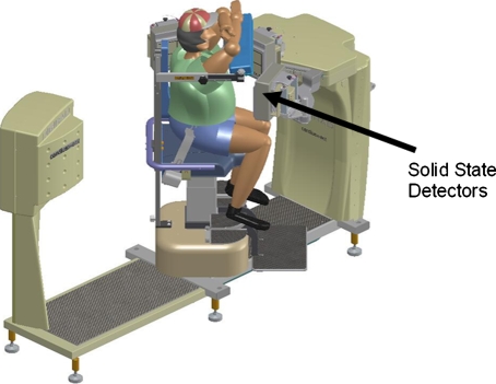
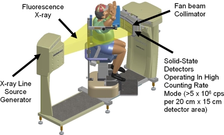
The X-ACT system consists of three detector head, each with a 20 cm × 15 cm FOV. Image acquisition uses an upright geometry where the patient sits in a chair that rotates during the data acquisition while the detector heads stay stationary. Each detector is mounted with a high sensitivity high resolution fan beam collimator. The detector heads are solid state and can operate at counting rates in excess of 5 M cps per 20 cm × 15 cm detector area.
Emission mode
In the emission mode the detectors are oriented to point at the axis-of-rotation (AOR) of the system. During setup, the patient’s heart is positioned on the AOR by translating the chair (cardio-centric imaging, Figure 1). As a result of this setup, the patient’s heart remains in the center of the emission imaging FOV throughout the emission scan. The detector heads are pushed as close to the patient as possible for best image quality. The patient chair rotates by 67.5° to complete the emission scan, the triple-head geometry will thus acquire data in a total of 202.5° range. This high-efficiency triple-head configuration13 used in combination with 3D-OSEM reconstruction enables emission scans to be performed up to four times faster than that of a conventional dual-head system.7 SPECT emission studies can be completed in as little as 3 min.
Figure 1.
X-ACT system configuration for emission scans
Transmission mode
When the emission acquisition is completed, the patient and chair stay stationary. The three detectors automatically reconfigure to form a single large 27″ (69 cm) transaxial detector arc (Figure 2). The focal line of the collimator of each head co-aligns with the spatial location of the transmission line source to form a fan beam transmission acquisition geometry. The focal length of the fan beam geometry is 150.0 cm, and the detector arc is 39.1 cm away from the AOR. When the transmission scan starts, the chair will first rotate 206° with the transmission source on to acquire the transmission data, then rotate 206° in the reverse direction with the transmission source off to acquire the contamination data from emission sources in the patient to the transmission data.
Figure 2.
X-ACT system configuration for transmission scans
The effective transmission imaging FOV is 50.0 cm in transaxial direction and 15 cm in axial direction. Since the patient’s heart stays at the AOR during the transmission scan as well, the 50-cm FOV essentially makes the critical left side truncation of the patient14 very unlikely, demonstrating a significant advantage of the X-ACT system over other hybrid SPECT/CT systems or small FOV SPECT systems using radionuclide transmission sources for cardiac SPECT.
Transmission line source assembly
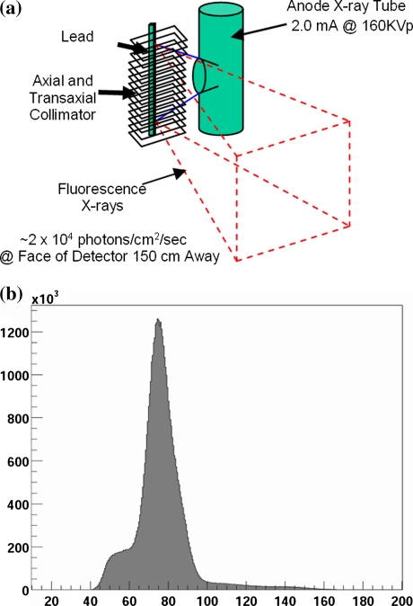
The transmission source assembly15 on the X-ACT system consists of a lead target, a low-dose, fixed anode x-ray tube, a lead collimator, and lead shields. When a transmission scan is started, the x-ray tube is turned on, and a narrow polychromatic x-ray beam from the tube illuminates the lead target. The lead target in turn emits lead fluorescence x-ray photons. The lead target is positioned at the focal line of the fan beam transmission acquisition geometry. The lead collimator collimates the lead fluorescence x-ray photons in both axial and transaxial directions to form the effective transmission line source (Figure 3a). The assembly is designed so that the x-ray beam from the x-ray tube does not exit the collimator directly. The transmission flux rate of the X-ACT system, when the x-ray tube is operated at 160 kVp and 2.0 mA, is about 2,080 counts per pixel per second.11 Compared to about 500 counts per pixel per 20 s (25 counts per pixel per second) in conventional SPECT systems with radionuclide transmission sources,16 the X-ACT transmission source shows a factor of over 80 times increase in the flux density. Note that this comparison is normalized to the same transmission acquisition pixel size of 3.5 mm. Also note that the flux rate for CT scans in SPECT/CT systems can be two to three magnitudes higher than the transmission source in XACT system, depending upon the CT protocol that is used.
Figure 3.
A Illustration of transmission line source generation. The red dash lines depict the transmission flux. B The transmission flux spectrum measured on the X-ACT system
The lead fluorescence x-ray energies at different emission lines and their relative intensities17 are shown in Table 1. The energies of the five emission lines are confined to a narrow range from 72.8 to 87.3 keV. The generated transmission source of the X-ACT system is a virtual monoenergetic source as seen by the detectors (Figure 3b) with a mean energy of 77 keV, leading to no beam hardening artifacts for the intended use.
Table 1.
Energies and relative intensities of the five lead (82Pb) x-ray emission lines (100 is assigned to the strongest line)17
| Kα2 | Kα1 | Kβ3 | Kβ1 | Kβ2 | |
|---|---|---|---|---|---|
| E (keV) | 72.8 | 75.0 | 84.5 | 84.9 | 87.3 |
| Intensity | 60 | 100 | 12 | 23 | 8 |
Image reconstruction
For transmission image reconstruction, the transmission data are first corrected using the acquired emission contamination data by subtracting the latter from the former pixel by pixel. The logarithm of the ratio of the reference (from blank scans) to the corrected transmission data is then calculated for each pixel to obtain the line integral of the linear attenuation along the corresponding line. Finally, a two-dimensional OSEM algorithm is used to reconstruct the attenuation map. After the reconstruction, the value of each voxel of the attenuation map is scaled as follows:
 |
1 |
where mu is the reconstructed value in the voxel, μ77 is the linear attenuation coefficient of water at 77 keV, pxlsz is the pixel size of the map, and mI is the short integer after scaling. After this scaling, the attenuation map is essentially a low-resolution volume CT image (with voxel value equal to the corresponding Hounsfield unit plus 1000). The scaling is done for the purposes of image storage, communication, and display only.
For emission image reconstruction, X-ACT uses a 3D-OSEM algorithm that models depth-dependent spatial resolution, nonuniform attenuation,18 and photon scatter.19 When used for AC, the saved attenuation map is scaled voxel by voxel to give the linear attenuation value for each voxel at the energy of interest. For example, for Tc-99m,
 |
2 |
where μ140 is the linear attenuation coefficient of water at 140 keV.
Anthropomorphic Phantom Study with Uniform Cardiac Insert
Following the SPECT/TCT protocol per ASNC guideline,20 we performed an anthropomorphic torso phantom (38 cm × 26 cm, Data Spectrum Corporation, Hillsborough, NC, USA) study with uniform cardiac insert. The recommended Tc-99m activity introduction to the phantom is with following concentration:
- Heart
6.8 μCi/cc (252 kBq/mL)
- Background
.7 μCi/cc (26 kBq/mL)
- Liver
4.0 μCi/cc (148 kBq/mL)
- Lungs
.0 μCi/cc (0 kBq/mL)
The phantom was placed on the patient chair with its cardiac insert positioned at the AOR by translating the chair. The emission scan was acquired with 30 seconds per step with a total of 20 steps. Again, the emission data had 60 projection views in 202.5°. The transmission data was acquired with 1 minute followed by another minute of the acquisition of emission contamination data. The radius of the circular orbit of the emission acquisition was 25.4 cm.
The ASNC guidelines require that the reconstructed attenuation coefficient of water at 140 keV should be in the range of .145-.161 cm−1 measured in two small regions of interest (ROIs), one at the liver and one at the cardiac insert. The AC image should be more uniform than the NC image and no region of the heart in the AC images should be noticeably hotter than the rest. The anterior-posterior and septal-lateral wall ratio should be in the range of 1 ± .1.
We performed visual assessment of the uniformity of the AC and NC images based on three-view images. For quantitative assessment, we did the ASNC specified wall ratio calculation followed by a 17-segment perfusion score statistic test. Wall scores were obtained by dividing the whole polar map into five segments, including the central circular segment as apex and the other four as anterior, lateral, inferior, and septal walls for the wall ratio calculation. For the statistic test, we first generated the 17-segment perfusion scores using QPS (Artificial Intelligence in Medicine, Cedars-Sinai Medical Center, CA, USA) and then calculated the mean and standard deviation of the segment scores. Since the segment scores are normalized to the maximum voxel value on the myocardium wall and the maximum voxel value is set to 100 in QPS, a more uniform image should have an average segment score closer to 100 and a smaller standard deviation than a less uniform image.
Anthropomorphic Phantom Study with Nonuniform Cardiac Insert
Using the same anthropomorphic phantom and acquisition protocol above but with two defects in the cardiac insert, we evaluated the effect of AC on the defect contrast (DC) in the reconstructed images. One defect was a 60° full defect located at the mid-anterior wall and the other was a 45° 50% defect located at the basal-inferior wall. The radius of the circular orbit of the emission acquisition was 25.8 cm.
After image reconstruction, we first generated the 17-segment perfusion scores of the image of the cardiac insert, then calculated the DC for each defect as
 |
3 |
where Def is the perfusion score of the segment with the defect and Bkg is the average of the perfusion scores of the direct neighboring segments of the segment with the defect. This calculation was done for both the AC and NC images for comparison.
ACR Phantom Study
Finally, we performed an ACR phantom (Deluxe Jaszczak Phantom, Data Spectrum Corporation, Hillsborough, NC, USA) study per the American College of Radiology procedure.21 The phantom was filled with 15 mCi (555 MBq) of Tc-99m. The emission data were acquired with 20 s per step and a total of 20 steps. The acquired emission data had 60 projection views in 202.5° with a total of 28 million counts. The radius of the circular orbit of the emission acquisition was 21.0 cm.
For all of these phantom studies, the x-ray tube was operated at 160 kVp and 2.0 mA. The fan beam collimator had a focal-length of 150.0 cm, hole size of .15 cm, and thickness of 2.7 cm. The orbit radius of the transmission scans was 39.1 cm. For both transmission and emission, data acquisition used a pixel size of 6.5 mm and image reconstruction used a voxel size of 6.5 mm. Scatter correction was not performed for all the NC images because the clinical protocols do not do scatter correction for NC image reconstruction. Scatter correction was not performed for AC of the ACR phantom studies because the scatter model used in XACT was designed for cardiac SPECT only.
Emission/Transmission Registration
In order to measure the emission/transmission coregistration error, we put three extended point sources22 at different positions in the emission FOV for coregistration scans. The coregistration scans used the same protocols for patient studies except that the source strength allowed much shorter emission scans.
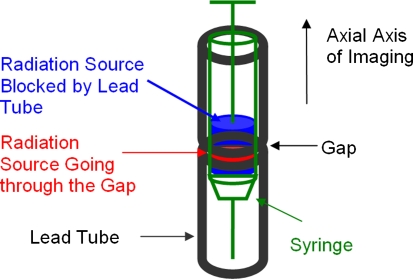
The extended point source used in this work (Figure 4) was a novel “synthesized source.” A tube made of shielding material (lead) of the radioactive source was positioned along the axial axis of the system. The tube had a small gap in the middle without lead. A syringe with Tc-99m source was put into the tube to form the effective point source. The radioactive source in the syringe extended to and spanned the gap of the tube. The emission photons were blocked by the tube except at the gap. For emission, the cross section of the syringe in the transaxial plane defined the transaxial dimension of the source and the gap of the tube defined the axial dimension of the source. For transmission, however, the cross-section of the lead tube in the transaxial plane defined the transaxial dimension of the source and the gap defined the axial dimension of the source. With this configuration, the source had excellent contrast in both emission and transmission images.
Figure 4.
Illustration of the extended point source for emission/transmission coregistration. The emission source in the syringe that is not blocked by the lead tube serves as the point source that appears as a hot point in the emission image. The cross section of the lead tube at the gap defines the transaxial dimension of the point source in transmission image and the gap defines the axial dimension. The point source in transmission image appears as a cold point. The syringe has a outer diameter of 1.0 cm, the lead tube has an inner diameter of 1.2 cm. The gap is 2-3 mm
The position of the point source in the emission image can be calculated using a conventional center-of-mass approach. In the transmission image, however, the position computation is slightly more complicated. A coregistration program first identifies the lead tube then sums the voxels in the transaxial plane to obtain a line profile of the tube. The gap of the lead tube corresponds to the valley of this line profile (negative contrast). The program then calculates the inverse log of the line profile so that the gap of the lead tube becomes a peak (positive contrast). Then a one-dimensional center-of-mass calculation is used to obtain the axial position of the source. Once the axial position is obtained, the transaxial slice with the gap and three transaxial slices of the lead tube above and below (a total of seven slices) are summed together to calculate the transaxial position of the source using the conventional center-of-mass approach.
We repeated the coregistration scan 12 times in different days on the same X-ACT system used for this work, of which 6 were with 10-second emission scans (one-second per step, 10 steps, total of 30 projection views in the emission data) and 6 were with 20-second emission scans (1-second per step, 20 steps, total of 60 projection views in the emission data). Transmission scans were acquired with 72 projection views in 1 minute. The sources were repositioned for each coregistration scan so that they were at random positions in the images.
For each emission/transmission scan of the three extended point sources, the coregistration program would first find the positions of each of the point sources in the reconstructed emission and transmission images. The position information was then fed to a program to calculate the position difference of the same point source in the emission and transmission images. The absolute value of the average of the position difference of the three point sources was then reported as the coregistration error. The program also reported the maximum of the absolute position difference of the three sources.
Results
Accuracy of the Reconstructed Attenuation Maps
The measured count rate for the blank scans in this work was 4.83, 5.06, and 5.00 Mcps for the three heads, respectively. Figure 5 shows a transaxial slice of the uniform cylindrical phantom, two slices of the anthropomorphic phantom, one at the cardiac insert region and one at the liver region, in the reconstructed attenuation maps of the phantoms. White circles in the images show the ROIs used for quantitative analysis of the maps.
Figure 5.
Reconstructed attenuation maps of the uniform region of the ACR phantom and the anthropomorphic phantom. The white circles are the ROIs used for the attenuation coefficient calculation
The detailed ROI information and the quantitative results of the mean and standard deviation are stated below. The reconstructed attenuation maps are quantitatively accurate according to the ASNC guideline requirement and of very low noise.
Uniform region of the ACR phantom: slice thickness: .65 cm, ROI radius: 9.49 cm, number of voxels in ROI: 667, the reconstructed attenuation coefficient of water @140 keV in the ROI: .150 ± .003 cm−1 (mean ± standard deviation).
Anthropomorphic phantom, heart region: slice thickness: .65 cm, ROI radius: 5.33 cm, number of voxels in ROI: 213, the reconstructed attenuation coefficient of water @140 keV in the ROI: .157 ± .006 cm−1 (mean ± standard deviation). Note that the ROI for attenuation coefficient calculation for the heart region included the Lucite “membrane” of the cardiac insert (the solid thin layers of material that defines the “left ventricle wall” of the insert), which has a density of 1.19 g · cm3 (19% higher than that of water, i.e., 1.0 g · cm3). When the cardiac insert was moved out and the scan was repeated, the attenuation coefficient of water at the same ROI was .151 ± .002 cm−1.
Anthropomorphic phantom, liver region: slice thickness: 1.95 cm, ROI radius: 6.37 cm, number of voxels in ROI: 304, the reconstructed attenuation coefficient of water @140 keV in the ROI: .154 ± .004 cm−1 (mean ± standard deviation). When a smaller ROI (radius 3.51 cm, 88 voxels) was used so that the ROI did not touch the liver boundary (also made of Lucite), the mean ± standard deviation was .151 ± .003 cm−1.
Image Uniformity
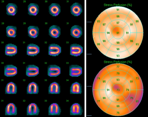
Figure 6 shows the images of the uniform cardiac insert of the anthropomorphic phantom and the 17-segment perfusion maps and scores. Table 2 illustrates the quantitative results, including inferior to anterior wall ratio (Inf/Ant), septal to lateral wall ratio (Sept/Lat), and 17-segment perfusion scores (average ± standard deviation). AC significantly improved the uniformity of the image, both visually and quantitatively. A simple two-tail paired t-test of the AC and NC 17-segment scores showed that the difference between AC and NC (increased average segment score by AC versus AC) was statistically significant (P < .0001).
Figure 6.
Images and 17-segment perfusion scores of the uniform cardiac insert: first/top: AC, second/bottom: NC. AC significantly improved the uniformity as compared to NC
Table 2.
Inferior to anterior wall ratio (Inf/Ant ratio), septal-to-lateral wall ratio (Sept/Lat ratio), and the average ± standard deviation of the 17-segment perfusion scores for the NC and AC images
| Inf/Ant ratio | Sept/Lat ratio | 17-Segment | |
|---|---|---|---|
| NC | .99 | 1.17 | 78.3 ± 6.5* |
| AC | 1.02 | 1.00 | 87.9 ± 3.3* |
*P < .0001 for two-tail paired t-test of the 17-segment scores of NC and AC.
Defect Contrast
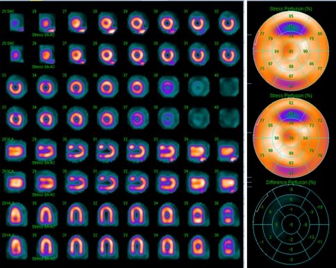
Figure 7 displays the images of the cardiac insert with defects and the 17-segment perfusion maps and scores. The calculated DCs are shown in Table 3. The DC was visually comparable for both the full and 50% defects in the AC and NC images. Quantitatively, AC images had a noticeable DC increase over the NC images for the full defect but only a marginal improvement for the 50% defect.
Figure 7.
Images and 17-segment perfusion polar maps and scores of the cardiac insert with two defects: first/top: AC, second/bottom: NC. Defect contrast was visually comparable for the AC and NC images, but the calculated defect contrast was noticeably higher in the AC images for the full defect (AC .628 vs NC .528)
Table 3.
Calculated defect contrast (DC) of the images of the cardiac insert with two defects
| DC, Full defect | DC, 50% defect | |
|---|---|---|
| NC | .528 | .156 |
| AC | .628 | .173 |
ACR Image Quality
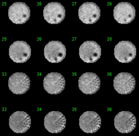
Figure 8 shows the reconstructed ACR phantom images with and without AC. AC corrected the bowing effect due to attenuation in the NC image. AC images have balanced intensity in the transaxial slices but the NC images are dimmer in the center than at the edge (bowing effect).
Figure 8.
Images of an ACR phantom with AC (first and third rows) and NC (second and fourth rows) using 6.5-mm pixel size as recommended in the ASNC guidelines for cardiac SPECT.23 AC corrected the bowing artifact due to attenuation (central region of a uniform region appeared dimmer than the outer region as was shown in the NC image). Note that the phantom had a diameter of 20 cm that was of the same size of the detector for emission scans. When fan beam geometry was used, the emission image was slightly truncated (partial truncation rings shown in the images). Scatter correction was not performed for either AC or NC
Emission/Transmission Registration
Table 4 shows the measured coregistration error in mm (absolute of the average position difference of the three sources) and the maximum of absolute position difference of the three point sources for the 12 coregistration scans. Note that for each scan, the maximum position differences at different directions could be from different point sources, i.e., the maximum difference in x direction could be from one point source and the maximum difference in y direction could be from another point source. Both of these measures showed good system coregistration.
Table 4.
Coregistration error and the maximum of absolute position difference of the three point sources (in mm) in x, y, z directions, where z is along the axial direction of the system, x and y are along the two orthogonal directions in the transaxial plane
| Scan | Coregistration error (mm) | Maximum position difference (mm) | ||||
|---|---|---|---|---|---|---|
| x | y | z | x | y | z | |
| 1 | .0 | .2 | .0 | .5 | 1.1 | .2 |
| 2 | .2 | .1 | .0 | .5 | .9 | 1.2 |
| 3 | .6 | .1 | .0 | 1.6 | 1.7 | .5 |
| 4 | .6 | .1 | .0 | 2.0 | 2.1 | .9 |
| 5 | .2 | .0 | .0 | 1.7 | 1.3 | .4 |
| 6 | .3 | .2 | .0 | 1.5 | 1.6 | .6 |
| 7 | .3 | .1 | .0 | 1.7 | 1.7 | .7 |
| 8 | .2 | .1 | .0 | 1.2 | 1.7 | 1.9 |
| 9 | .4 | .2 | .0 | 2.2 | 1.5 | .5 |
| 10 | .4 | .4 | .0 | 2.2 | 1.7 | .5 |
| 11 | .5 | .4 | .0 | 2.1 | 1.2 | .4 |
| 12 | .8 | .0 | .0 | 2.4 | 1.5 | .6 |
Summary and Discussion
The phantoms used in this work were stationary phantoms, meaning, respiratory motion or cardiac beating was not present. The results showed that the X-ACT system generated high quality, accurate attenuation maps, improved image uniformity and defect contrast. The system also showed accurate intrinsic emission/transmission registration. For emission/transmission registration in patient scans, our previous volunteer human studies showed that even though transmission scans could be completed within 1 minute or even a shorter period of time, as long as the transmission scans included two or more respiratory cycles, no respiratory motion introduced emission/transmission misregistration was observed.24 Patient studies also showed less transmission/emission misregistration than those reported of PET/CT or SPECT/CT systems.25
We notice that X-ACT transmission photons (~77 keV) have lower penetration power than Gd-153 transmission photons (~100 keV) due to the energy difference between the two. The effective flux rate advantage of the X-ACT transmission source over the Gd-153 transmission sources will decrease as the patient size increases. Starting from a ratio of 80, Table 5 illustrates the effective ratio of the transmission flux rate of the X-ACT transmission source to that of Gd-153 sources when passing through different thicknesses of water. The X-ACT transmission source is effectively 43 times as strong as Gd-153 source when passing through 40 cm of water, and 32 times as strong when passing through 60 cm of water.
Table 5.
Effective flux rate ratio of the X-ACT transmission source to that of Gd-153 transmission sources when passing through different thicknesses of water, starting with a ratio of 80 at 0 cm. The x-ray tube is operated at 160 kVp and 2.0 mA
| Water (cm) | 0 | 10 | 20 | 30 | 40 | 50 | 60 |
|---|---|---|---|---|---|---|---|
| Ratio | 80 | 69 | 59 | 51 | 43 | 37 | 32 |
The anthropomorphic phantom used in this work is a medium to large torso phantom with lateral dimension of 38 cm and anterior/posterior dimension of 26 cm. The transmission flux rate from the blank scan measurement was about 76 times that of the Gd-153 sources. The effective transmission flux rate of the X-ACT transmission source for this phantom study was about 41 times that of the Gd-153 sources. Therefore, a 1-minute transmission scan using the X-ACT system had about 14 times (41/3 ≈ 14) the counts as a 3-minute scan using Gd-153 transmission sources. This explains the observed low noise level in the reconstructed attenuation maps. And similarly, for the same medium to large torso phantom, a 30-second transmission scan will result in about 7 times the counts of a 3-minute transmission scan using Gd-153 sources on current commercial systems, this suggests that one can do 30-second transmission scans using the X-ACT system and still obtain high quality transmission data, allowing 1-minute total transmission scan time that includes both the transmission acquisition and the emission contamination acquisition. Note that from the transmission flux rate point of view, the flux rate of the in-line hybrid SPECT/CT systems is about three magnitudes higher than that of the X-ACT system.
For blank scan quality control (QC), a blank scan is performed in the beginning of the day prior to patient studies. The blank scan generates three planar images, one for each small detector head. The technologist will first visually check if there are any abnormal patterns in the planar images as compared to the blank scan data from the previous imaging day and then check the data header of each planar image to make sure that the total count rate is above 4 Mcps. For several systems we tracked, the blank scans had been shown to be very stable. For example, the blank scans in over 190 days of the XACT system in a clinical site showed no pattern changes, and the count rate varied very slightly from day to day. The count rate on the first day of imaging was 5.15, 5.50, and 5.39 Mcps for the three heads, and 195 days later, was 5.08, 5.59, and 5.34 Mcps, for the three heads, respectively. For alignment QC, the emission/transmission coregistration phantom scan is performed weekly, along with the emission center of rotation (COR) QC.
This work has been focused on the evaluation of the performance of the system on Tc-99m imaging. When used for Tl-201 imaging, the attenuation maps obtained from the transmission scan is at almost the same energy as the Tl-201 emission; therefore, energy scaling of the attenuation map as shown in Eq. (2) is not necessary. Also, when using Eq. (2) for energy scaling, the spine in the anthropomorphic phantom had attenuation coefficient of .285/cm at 140 keV. According to the vendor (Data Spectrum Corporation, Hillsborough, NC, USA), the spine is made of “high density” “virgin” Teflon, the narrow beam measurements of its attenuation coefficient at 140 keV is .2853/cm. The energy scaling using Eq. (2) for the spine in the phantom was very close to the vendor’s specification. Also, since bone structures account for only about 5% of the total volume in the torso, we simply use Eq. (2) to energy scale the attenuation maps without differentiating bones from other tissues.
Conclusion
The transmission flux rate of the X-ACT system is about 80 times that of conventional SPECT AC systems with radionuclide transmission sources. The fully integrated SPECT/VCT design eliminates the need for patient translation between emission and transmission scans. Phantom studies showed that the X-ACT system generated high quality and quantitatively accurate attenuation maps. AC using the reconstructed attenuation maps in a 3D OSEM algorithm improved image quality and image uniformity as desired.
Acknowledgments
The authors thank Yolando Panganiban and Mike O’Donnell for help with the coregistration phantom design, Diana Solis, Daniel Sparks, and Peter Maffetone for software implementation and release. They also thank Craig Thompson and Chad Eastridge for hardware and firmware implementation.
Open Access
This article is distributed under the terms of the Creative Commons Attribution Noncommercial License which permits any noncommercial use, distribution, and reproduction in any medium, provided the original author(s) and source are credited.
Footnotes
This work was supported by Digirad Corporation, Poway, CA 92064, USA.
References
- 1.Cullom SJ, Case JA, Bateman TM. Attenuation correction for cardiac SPECT: Clinical and developmental challenges (invited commentary) J Nucl Med. 2000;41:860–862. [Google Scholar]
- 2.Germano G, Slomka PJ, Berman DS. Attenuation correction in cardiac SPECT: The boy who cried wolf? J Nucl Cardiol. 2007;14:25–35. doi: 10.1016/j.nuclcard.2006.12.317. [DOI] [PubMed] [Google Scholar]
- 3.Singh B, Bateman TM, Case JA, Heller G. Attenuation artifact, attenuation correction, and the future of myocardial perfusion SPECT. J Nucl Cardiol. 2007;14:153–164. doi: 10.1016/j.nuclcard.2007.01.037. [DOI] [PubMed] [Google Scholar]
- 4.Gibson PB, Demus D, Noto R, et al. Low event rate for stress-only perfusion imaging in patients evaluated for chest pain. J Am Coll Cardiol. 2002;39:999–1004. doi: 10.1016/S0735-1097(02)01720-5. [DOI] [PubMed] [Google Scholar]
- 5.Heller GV, Links J, Bateman TM, et al. American Society of Nuclear Cardiology and Society of Nuclear Medicine joint position statement: Attenuation correction of myocardial perfusion SPECT scintigraphy. J Nucl Cardiol 2004;11:229-30 [DOI] [PubMed]
- 6.Watson DD. Is it time for SPECT attenuation correction? J Nucl Cardiol. 2004;11:239–241. doi: 10.1016/j.nuclcard.2004.03.006. [DOI] [PubMed] [Google Scholar]
- 7.Maddahi J, Mendez R, Mahmarian JJ, et al. Prospective multicenter evaluation of rapid, gated SPECT myocardial perfusion upright imaging. J Nucl Cardiol. 2009;16:351–357. doi: 10.1007/s12350-009-9063-3. [DOI] [PubMed] [Google Scholar]
- 8.Patton JA, Turkington TG. SPECT/CT physical principles and attenuation correction. J Nucl Med Technol. 2008;36:1–10. doi: 10.2967/jnmt.107.046839. [DOI] [PubMed] [Google Scholar]
- 9.Goetze S, Wahl RL. Prevalence of misregistration between SPECT and CT for attenuation-corrected myocardial perfusion SPECT. J Nucl Cardiol. 2007;14:200–206. doi: 10.1016/j.nuclcard.2006.12.325. [DOI] [PubMed] [Google Scholar]
- 10.Bai C, Shao L, Da Silva AJ, Zhao Z. A generalized model for the conversion from CT numbers to linear attenuation coefficients. IEEE Trans Nucl Sci. 2003;50:1510–1515. doi: 10.1109/TNS.2003.817281. [DOI] [Google Scholar]
- 11.Conwell R, Kindem J, Bai C, Maddahi J. A novel cardiac SPECT system with X-ray-based attenuation correction using the same solid state detectors for both emission and transmission scans. J Nucl Med. 2008;49:64. doi: 10.2967/jnumed.107.046391. [DOI] [Google Scholar]
- 12.Chalmers GJ. Structural shielding design for medical X-ray imaging facilities (NCRP Report No 147) Phys Med Biol. 2005;50:4243–4244. doi: 10.1088/0031-9155/50/17/B01. [DOI] [Google Scholar]
- 13.Lewin H, Hyun M. A clinical comparison of an upright triple-head digital detector system to a standard supine dual-head gamma camera. J Nucl Cardiol. 2005;12:S113. doi: 10.1016/j.nuclcard.2005.06.042. [DOI] [Google Scholar]
- 14.Chen J, Galt JR, Durbin MK, et al. Transmission scan truncation with small-field-of-view dedicated cardiac SPECT systems: Impact and automated quality control. J Nucl Cardiol. 2005;12:567–573. doi: 10.1016/j.nuclcard.2005.04.013. [DOI] [PubMed] [Google Scholar]
- 15.Kindem J, Conwell R, Bai C. Fluorescence x-ray line source generated by x-ray tube. US Patent (pending), 2008
- 16.Celler A, Dixon KL, Chang Z, et al. Problems created in attenuation-corrected SPECT images by artifacts in attenuation maps: A simulation study. J Nucl Med. 2005;46:335–343. [PubMed] [Google Scholar]
- 17.X-Ray Data Booklet Table 1-3. http://xdb.lbl.gov/Section1/Table_1-3.pdf
- 18.Bai C, Zeng GL, Gullberg GT. A slice-by-slice blurring model for 3D scatter compensation in parallel and converging beam SPECT. Phys Med Biol. 2000;40:1275–1307. doi: 10.1088/0031-9155/45/5/314. [DOI] [PubMed] [Google Scholar]
- 19.Bai C, Conwell RL. Emission-data-based photon scatter correction in computed nuclear imaging technology. US patent 7569827, 2009
- 20.Nichols KJ, Bacharach SL, Bergmann SR, et al. Instrumentation quality assurance and performance. J Nucl Cardiol. 2007;14:e61–e78. doi: 10.1016/j.nuclcard.2007.09.024. [DOI] [PubMed] [Google Scholar]
- 21.Site scanning instructions for use of the nuclear medicine phantom for the ACR Nuclear Medicine Accreditation Program, American College of Cardiology. http://www.acr.org/accreditation/nuclear/qc_forms/FeaturedCategories/qc_forms/SPECT_Phantom_Instructions.aspx
- 22.Bai C, Conwell RL, Kindem J (2009) Extended point source concept for multi-modality imaging coregistration. US Patent (pending), 2009
- 23.Hansen CL, Goldstein RA, Akinboboye OO, et al. Myocardial perfusion and function: Single photon emission computed tomography. J Nucl Cardiol. 2007;14:e39–e60. doi: 10.1016/j.nuclcard.2007.09.023. [DOI] [PubMed] [Google Scholar]
- 24.Conwell R, Bai C, Maffetone P. Evaluation of the respiratory motion effect on transmission scans using an ultra-low dose X-ray-derived source. J Nucl Med. 2009;50:294P. [Google Scholar]
- 25.Conwell R, Babla H, Bai C, Kindem J, Maddahi J. Evaluation of image registration in a solid state cardiac SPECT system with an ultra-low dose X-ray-based attenuation correction. J Am Coll Cardiol. 2009;53:A231. doi: 10.1016/j.jacc.2009.01.017. [DOI] [Google Scholar]


