Abstract
This paper presents the latest development of a lead-free piezoelectric ceramic and its application to transducers suitable for high-frequency ultrasonic imaging. A lead-free piezoelectric ceramic with formula of (K0.5Na0.5)0.97Li0.03(Nb0.9 Ta0.1)O3 (abbreviated as KNLNT-0.03/0.10) was fabricated and characterized. The material was found to have a clamped dielectric constant ε33S = ε0 = 890, piezoelectric coefficient d33 = 245 pC/N, electromechanical coupling factor kt = 0.42 and Curie temperature Tc > 300 °C. High-frequency (40 MHz) ultrasound transducers were successfully fabricated with the lead-free material. A representative lead-free transducer had a bandwidth of 45%, two-way insertion loss of −18 dB. This performance is comparable to reported performances of popular lead-based transducers. The comparison results suggest that the lead-free piezoelectric material may serve as an alternative to lead-based piezoelectric materials for high-frequency ultrasonic transducer applications.
Keywords: Piezoelectric materials, Lead-free, high frequency, ultrasound transducer
Introduction
In recent years, high frequency (30–150 MHz) ultrasound imaging has been used extensively for imaging of eyes, blood vessels, skin, and small animals [1][2]. In ultrasound imaging, transducers, which ultimately determine the resolution of the images, play a critical role. To build high-performance (high sensitivity and broad bandwidth) ultrasound transducers, the first decision that has to be made is the selection of the piezoelectric materials. Among a wide range of the piezoelectric materials, lead-based piezoelectric materials such as lead zirconate titanate ceramics (abbreviated as PZT) and Pb(Mg1/3Nb2/3)O3-PbTiO3 (abbreviated as PMN-PT) single crystal materials exhibit excellent piezoelectric performance, thus they have been widely used. However, due to environmental concerns, many countries and organizations are now restricting the use of lead-based materials [3][4]. The development of alternative high-performance lead-free piezoelectric materials has generated much interest [3–5]. Thus in recent years, these materials such as alkali niobate-based materials, modified bismuth titanates and Bi0.5Na0.5TiO3-based materials have been extensively studied [6–8]. Among them, K0.5Na0.5NbO3 (abbreviated as KNN) is one of the most promising candidates because of its high Curie temperatures (about 420 °C), good ferroelectric properties (Pr = 33 µC/cm2) and large electromechanical coupling coefficient. Recent studies have shown that piezoelectric properties of KNN can be further improved by adding with Li and Ta. In this paper, we will report the fabrication and characterization of the newly-developed KNN ceramic (K0.5Na0.5)0.97Li0.03(Nb0.9Ta0.1)O3 (abbreviated as KNLNT-0.03/0.10) and its application in high-frequency ultrasound transducers. The measured results will also be compared to the reported data of certain lead-based transducers.
Methods
(K0.5Na0.5)0.97Li0.03 (Nb0.9Ta0.1)O3 ceramic samples were prepared by conventional a sintering technique using analytical-grade metal oxides or carbonate powders: Na2CO3 (99.8%), K2CO3 (99.9%), Li2CO3 (99%), Ta2O5 (99.99%), Nb2O5 (99.959%) [9][10]. The powders in the stoichiometric ratio of the compositions were thoroughly mixed with ethanol for 8 hours using zirconia balls, and then dried and calcined at 880 °C for 6 hours. After the calcinations, the mixture was ball-milled again and mixed with a PVA binder solution and then pressed into disk samples. The disk samples were finally sintered at 1070–1140 °C for 4 hours in air. Next, silver electrodes were pasted on the top and bottom surfaces of the samples. The samples were poled under a DC field of 4–5 kV/mm at 180 °C in a silicone oil bath for 30 minutes.
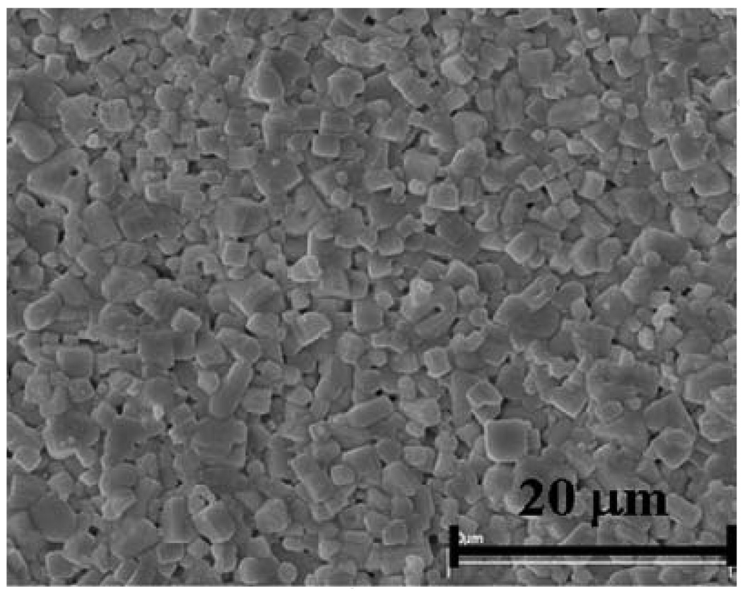
After this, the piezoelectric and dielectric properties of the lead-free material were characterized. The electromechanical coupling coefficient kt, the clamped dielectric constant ε33S/ε0 and loss tanδ were all measured with an Agilent 4294A electric impedance analyzer (Agilent Technologies, Englewood, CO); piezoelectric coefficient d33 was measured using a YE2730 d33 meter (APC International Ltd, Mackeyville, PA); density ρ was measured using the Archimedes’ method. Lastly, the longitudinal wave velocity was obtained using the pulse-echo method with a 40 MHz transducer. In the measurement, a Panametrics 5900PR (Panametrics Inc, Waltham, MA) was used as the pulse source; the time-of-flight was measured by a LeCroy LC534 1 GHz digital oscilloscope (LeCroy Corporation, Chestnut ridge, NY). All of the measured results are summarized in Table 1. The table shows that the lead-free ceramic exhibits a piezoelectric constant d33 of 245 pC/N, a relative dielectric constant ε33S/ε0 of 890, thickness mode electromechanical coupling coefficient kt of 0.42, while maintaining a low dielectric loss tan (δ) of 4.5%. The relative high dielectric constant of the ceramics makes it a possible candidate for small-aperture, single element transducers (such as needle transducers) and arrays. Meanwhile, high electromechanical coupling and low dielectric loss normally yield wide bandwidth and high sensitivity of the transducers. Furthermore, the Curie temperature TC of the material was found to be as high as 320 °C [9]. Lastly, grain size also is a very important factor in the fabrication of high-frequency transducers and arrays [11]. The scanning electron microscopy (SEM) of the KNLNT as given in Fig.1 shows that its grain size is around 2 µm, which is fine enough to build transducers below 50 MHz. For the purpose of comparison, properties of the popular lead-based piezo-materials PMN-33%PT and PbTiO3 are also listed in Table 1. PMN-PT is a relaxor-based ferroelectric single crystal exhibiting an extraordinary large electromechanical coupling coefficient and piezoelectric coefficients. Its superior properties make it very useful for making high-sensitivity broad bandwidth transducers. PbTiO3, on the other hand, is a piezo-ceramic offering a large thickness mode electromechanical coupling but with a very low planar electromechanical coupling constant. The two kinds of materials have been fabricated into single-element transducers and evaluated by Zhou et al [12] and Snook et al [13], respectively. The performance of the lead-free KNLNT transducer will be compared to them.
Table 1.
Piezoelectric materials parameters
| Material | kt | ε33S/ε0 | d33 (pC/N) |
ρ (g/cm3) |
c (m/s) |
tan (δ) |
Z (MRayl) |
|---|---|---|---|---|---|---|---|
| KNLNT-0.03/0.1 | 0.42 | 890 | 245 | 4544 | 6875 | 4.5 | 31 |
| PMN-33%PT[12] | 0.58 | 797 | 1430 | 8000 | 4608 | 0.5 | 37 |
| PbTiO3[13] | 0.49 | 200 | 50 | 6900 | 5200 | 1 | 35.9 |
kt is the thickness mode electromechanical coupling coefficient; ε33S/ε0 is the clamped dielectric constant; ρ is the density, c is the longitudinal wave velocity; tan(δ) is the dielectric loss and Z is the acoustic impedance.
Fig 1.
SEM micrograph of the KNLNT-0.03/0.10
The KNLNT transducer was designed with the KLM model-based simulation software PiezoCAD (Sonic Concepts, Woodinville, WA) with parameters list in Table.1. It should be noted that the common approach to compare different transducers would be to test the transducers with the same design parameters such as aperture size and focal depth. In this experiment, we just intend to roughly compare these transducers when they are 50-Ω electrically matched. In this design, to compensate for the acoustic impedance mismatch between the KNLNT (31 MRayls) and human tissues (around 1.5 MRayls) [11], 2–3µm silver epoxy (7.3 MRayls) and parylene (2.5 MRayls) were selected as the first and second front-face matching materials, respectively. In addition, to further improve the bandwidth of the transducers, conductive epoxy Esolder-3022 (5.9 MRayls) was used as backing material. Afterwards, transducers were carefully fabricated following the design parameters as summarized in Table 2. The bulk ceramic plate was first lapped down to the half-wavelength thickness and tuned to a 1-mm diameter to obtain 50-Ω electric impedance. The active element which includes first matching, piezo-material and backing was then housed in a copper tube. Parylene was finally evaporated onto the transducer front-face surface serving as the second matching layer and a protecting layer as well.
Table 2.
Design parameters
| Piezo-material | 1st matching Silver epoxy |
2nd matching parylene |
Backing E-solder 3022 |
|||||
|---|---|---|---|---|---|---|---|---|
| Material | Za | Ta | Zm1 | Tm1 | Zm2 | Tm2 | Zb | Tb |
| KNLNT-0.03/0.1 | 31 | 75 | 7.3 | 8.4 | 2.5 | 13.0 | 5.9 | >3mm |
Za, Zm1, Zm2 and Zb are acoustic impedance (in MRayl) of the piezoelectric material, first matching, second matching and backing material respectively; Ta, Tm1, Tm2 and Tb are thickness (in µm, except Tb) of the piezoelectric material, first matching, second matching and backing material respectively.
Results
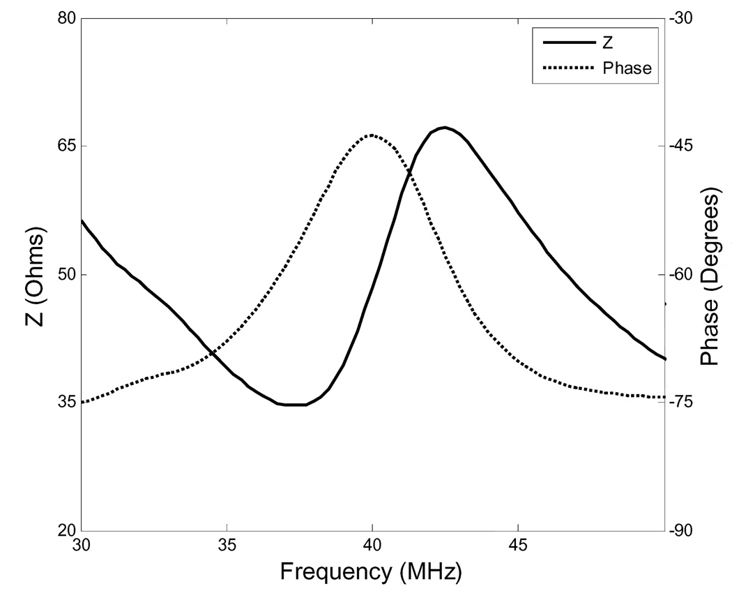
To experimentally evaluate the performance of the transducer, a set of measurements were performed. Firstly, an Agilent 4294A electric impedance analyzer was used to measure the electric impedance of the transducer in air. As shown in Fig.2, the measured value is consistent with expectations. Moreover, with the electric impedance plot, the electromechanical coupling coefficient kt can be determined from the following equation according to the IEEE standard [12]:
| (1) |
where fs is the series resonant frequency at which the conductance reaches the minimum and fp is the parallel resonant frequency at which the resistance reaches the maximum. In Fig.2, fs is 39.7 MHz, and fp is 43 MHz. According to equation (1), kt was calculated to be 0.42.
Fig 2.
Measured electric impedance of the KNLNT-0.03/0.10 transducer
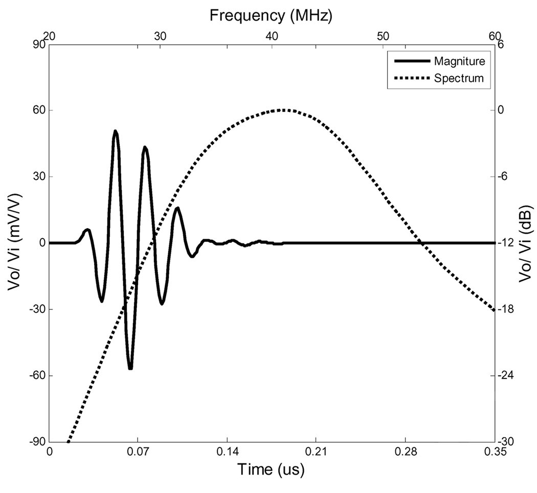
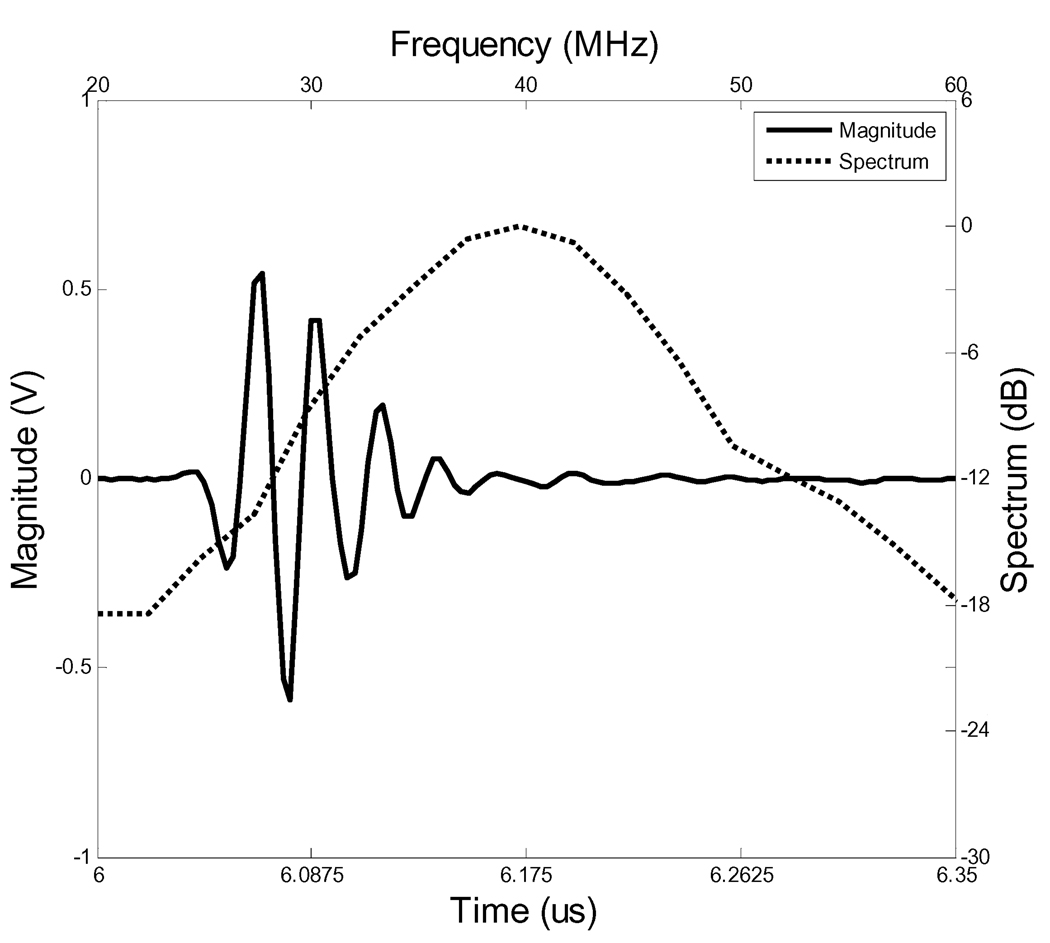
Next, the same experiment setup and the same loss compensation method reported by Zhou et al [13] and Snook et al [14] were used to measure the center frequency, bandwidth and insertion loss of the transducer. In the setup, a piece of quartz was immersed in a water bath as a target. Panametrics 5900PR (Panametrics Inc, Waltham, MA) and Tektronix AFG2020 function generator (Tektronix, Inc , Richardson, TX) were used as the signal sources for measurements of the center frequency, bandwidth and insertion loss, respectively. In these measurements, the quartz target was located at the natural focal distance of the transducer. In the insertion loss measurement, losses due to attenuation in the water bath and the transmission of the signal in the quartz target were compensated but the losses caused by diffraction were not included. In all measurements, the echo signals were acquired and displayed using the LeCroy LC534 1GHz digital oscilloscope. The measured pulse-echo response and its spectrum were plotted and compared to the modeled results. As shown in Fig.3 and 4, the measured pulse-echo response of the KNLNT transducer is consistent with the modeled prediction. The modeled and measured results of the KNLNT transducer and reported results of the PMN-33%PT and PbTiO3 transducers are summarized in Table 3. The KNLNT transducer yields a bandwidth (−6 dB) of 45% and the two-way insertion loss of −18 dB. Its bandwidth is similar to the reported values of the PMN-33%PT transducer (45%) and the PbTiO3 transducer (47%). Measured insertion loss of the KNLNT transducer is worse than the PMN-33%PT transducer (−15 dB) but better than the PbTiO3 transducer (−23.7 dB). The PMN-33% transducer has better sensitivity than the KNLNT transducer due to its much higher thickness electromechanical coupling. The PbTiO3 has the same thickness electromechanical coupling coefficient as KNLNT but higher acoustic impedance (35.9 MRayls). The matching layers are better matched to the KNLNT transducer because of its relatively lower acoustic impedance (31 MRayls). This may explain why the PbTiO3 transducer’s sensitivity is worse than that of the KNLNT transducer. The results reveal that the performance (sensitivity and bandwidth) of the KNLNT transducer can compete with the high-performance lead-based transducers.
Fig 3.
Simulation of the pulse-echo response of the KNLNT-0.03/0.10 transducer
Fig 4.
Measured pulse-echo waveform and its spectrum of the KNLNT 0.03/0.10 transducer
Table 3.
Modeling and measured results
| Modeling results | Measured results | |||||
|---|---|---|---|---|---|---|
| Material | Fc (MHz) | BW (%) | IL (dB) | Fc (MHz) | BW (%) | IL (dB) |
| KNLNT-0.03/0.1 | 40 | 47 | −11 | 40 | 45 | −18 |
| PMN-33%PT[12] | 45 | 48 | −9 | 44 | 45 | −15 |
| PbTiO3[13] | 61 | 27.7 | −19 | 45 | 47 | −23.7 |
Fc is the center frequency; BW is the −6dB bandwidth; IL is the two-way insertion loss.
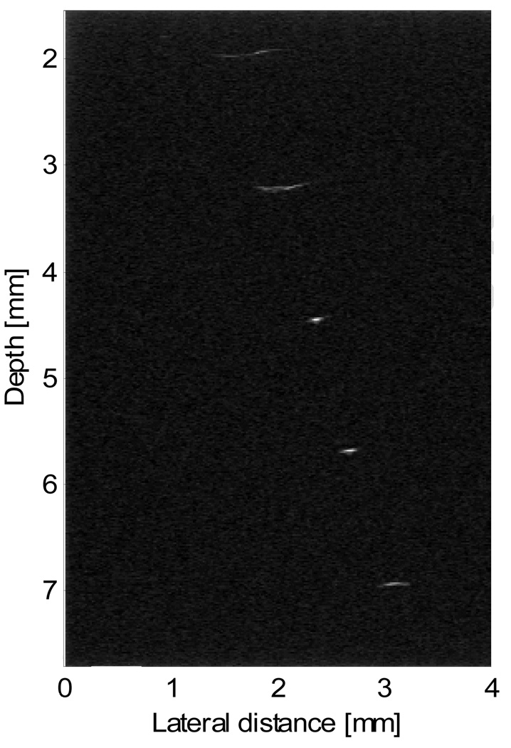
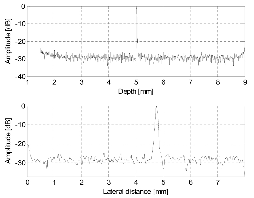
The final evaluation of the KNLNT transducer was to produce an image. To obtain a high-quality ultrasonic image, a focused transducer is necessary. The aperture size of the KNLNT transducer is only 1 mm. It’s very difficult to fabricate a focused transducer with such a small aperture size. A new KNLNT transducer with an aperture size of 2 mm, a center frequency of 40 MHz, a bandwidth of 47% and a focal distance of 5 mm was thus fabricated for acquiring ultrasonic images. Using a home-made UBM (Ultrasound Backscatter Microscopy) system, the new KNLNT transducer was used to scan a wire phantom. The wire phantom was mainly used to assess spatial resolutions of the transducers. In the phantom, five 20-µm diameter tungsten wires were arranged diagonally with equal distance in the axial (1.55 mm) and lateral (0.65 mm) directions. The pulse-echo image was acquired as the transducer scanned over the wires, which were immersed in the degassed water. The acquired image was displayed with the dynamic range of 40 dB as shown in Fig. 5. With the acquired phantom data, the −6 dB axial and lateral resolution of the transducer at the focal point (5 mm) were found to be 32 µm and 102 µm, respectively, as illustrated in Fig.6. Theoretically, for a circular transducer, the axial resolution, Rax, and the lateral resolution, Rlat at the focus are [2]:
where λ is the wavelength at the loading mediums, c is the speed at the loading mediums and BW is the bandwidth of the transducer. The theoretical axial and lateral resolutions were calculated to be 38 µm and 90 µm, respectively, which are consistent with the measured values.
Fig 5.
Wire-phantom image of the KNLNT-0.03/0.10 transducer with dynamic range of 40 dB.
Fig 6.
Axial resolution and lateral resolution of the KNLNT-0.03/0.10 transducer were calculated to be 32 um (top figure) and 102 um (bottom figure) respectively.
Conclusion
A lead-free piezoelectric ceramic with excellent piezoelectric and dielectric properties was successfully synthesized and characterized. High-frequency single element transducers based on the ceramic were fabricated, evaluated, and its performance compared to those of lead-based transducers. The experiment results are summarized as follows:
The lead-free piezoelectric ceramic (K0.5Na0.5)0.97Li0.03(Nb0.9 Ta0.1)O3 has the similar performance to lead-based materials in high-frequency ultrasound transducer applications.
The lead-free ceramic has a relatively high acoustic speed, making it especially suitable for high-frequency transducer applications.
The dielectric constant value of the ceramic makes it a candidate for small aperture applications, such as needle transducers or arrays.
The lead-free ceramic exhibits an excellent electromechanical coupling coefficient (kt = 0.42). With this material, it is possible to build high sensitivity, broad bandwidth ultrasound transducers suitable for medical imaging applications.
In summary, the KNLNT lead-free piezoelectric ceramic is a promising piezoelectric material and may serve as an alternative to lead-based piezoelectric materials in high-frequency ultrasonic transducer applications in the future.
Acknowledgments
This work has been partially supported by NIH grant # P41-EB2182. The authors would like to thank Dr. Changhong Hu and Mr. Jay Williams their aid with ultrasound imaging and the transducer fabrication process. Financial support from the PolyU internal grants (1-BBZ3 and 1-BB95) to authors from the Hong Kong Polytechnic University is also acknowledged.
Footnotes
Publisher's Disclaimer: This is a PDF file of an unedited manuscript that has been accepted for publication. As a service to our customers we are providing this early version of the manuscript. The manuscript will undergo copyediting, typesetting, and review of the resulting proof before it is published in its final citable form. Please note that during the production process errors may be discovered which could affect the content, and all legal disclaimers that apply to the journal pertain.
Contributor Information
D. W. Wu, NIH Transducer Resource Center and Department of Biomedical Engineering, University of Southern California, Los Angeles, CA 90089, USA.
R. M. Chen, NIH Transducer Resource Center and Department of Biomedical Engineering, University of Southern California, Los Angeles, CA 90089, USA
Q. F. Zhou, NIH Transducer Resource Center and Department of Biomedical Engineering, University of Southern California, Los Angeles, CA 90089, USA
K. K. Shung, NIH Transducer Resource Center and Department of Biomedical Engineering, University of Southern California, Los Angeles, CA 90089, USA
D.M. Lin, Department of Applied Physics and Materials Research Center, The Hong Kong Polytechnic University, Kowloon, Hong Kong
H. L. W. Chan, Department of Applied Physics and Materials Research Center, The Hong Kong Polytechnic University, Kowloon, Hong Kong
References
- 1.Foster FS, Pavlin CJ, Lockwwod GR, Ruyn LK, Harasiewicz KA, Berude L, Rauth AM. Principles and applications of ultrasound backscatter Microscopy. IEEE Trans. Ultrason. Ferroelect. Freq. Contr. 1993;40:608–617. doi: 10.1109/58.238115. [DOI] [PubMed] [Google Scholar]
- 2.Foster FS, Pavlin CJ, Harasiewicz KA, Christopher DA, Turnbull DH. Advances in ultrasound biomicroscopy. Ultrasound in Med.&Biol. 2000;26:1–27. doi: 10.1016/s0301-5629(99)00096-4. [DOI] [PubMed] [Google Scholar]
- 3.Saito Yasuyoshi, Takao Hisaaki, Tani Toshihiko, Nonoyama Tatsuhlko, Takatorl Kazumasa, Homma Takhlko, Nagaya Toshiatsu, Nakamura Masaya. Lead-free piezoceramics. Nature. 2004;432:84–87. doi: 10.1038/nature03028. [DOI] [PubMed] [Google Scholar]
- 4.Ringgaard Erling, Wurlitzer Thom. Lead-free piezoceramics based on alkali niobates. Journal of the European Ceramic Society. 2005;25:2701–2706. [Google Scholar]
- 5.Demartin Maeder M, Damjanovic D, Setter N. Journal of Electroceramics. 2004;13:385. [Google Scholar]
- 6.Matsubara Masato, Yamaguchi Toshiaki, Sakamoto Wataru, Kikuta Koichi, Yogo Toshinobu, Hirano Shin-ichi. Processing and piezoelectric properties of lead-free (K, Na) (Nb,Ta) O3 ceramics. Journal of America Ceramic Society. 2006;88:1190–1196. [Google Scholar]
- 7.Feuillard G, Loyau V, Tran Huu Hue LP, Wurlitzer T, Ringgard E, Wolny W, Malic B, Kosec M, Barzegar A, Damjanovic D, Lethiecq M. Comparative performances of new KNN lead-free piezoelectric materials and classical lead-based ceramics for ultrasonic transducer applications. IEEE Ultrasonic Symposium. 2003:1995. [Google Scholar]
- 8.Zhang SJ, Xia R, Shrout TR. Modified (KNa)NbO based lead-free piezoelectrics with broad temperature usage range. Applied Physics Letters. 2007;91:132913. [Google Scholar]
- 9.Lin DM, Kwok KW, Chan HLW. Microstructure, phase transition, and electrical properties of (K0.5Na0.5)1−xLix(Nb1−yTay)O3 lead-free piezoelectric ceramics. Journal of Applied Physics. 2007;102(34102):1–7. [Google Scholar]
- 10.Lin DM, Kwok KW, Tian HY, Chan HLW. Phase transitions and electrical properties of (Na1−xKx)(Nb1−ySby)O3 lead-free piezoelectric ceramics with MnO2 sintering aid. Journal of the American Ceramic Society. 2007;90:1458. [Google Scholar]
- 11.Shung KK, Zippuro M. Ultrasonic transducers and arrays. Engineering in Medicine and Biology Magazine. 1996;15:20. [Google Scholar]
- 12.ANSI/IEEE Standard on piezoelectricity, Std. 176-1987; New York: IEEE; 1987. [Google Scholar]
- 13.Zhou QF, Xu XC, Gottlieb EJ, Sun L, Cannata JM, Ameri H, Humayun MS, Han PD, Shung KK. PMN-PT single crystal high-frequency ultrasonic needle transducers for pulsed-wave Doppler application. IEEE Trans. Ultrason. Ferroelect. Freq. Contr. 2007;54:668–675. doi: 10.1109/tuffc.2007.290. [DOI] [PubMed] [Google Scholar]
- 14.Snook KA, Zhao JZ, Alves CF, Cannata JM, Chen WH, Meyer RJ, Ritter TA, Shung KK. Design, fabrication, and evaluation of high frequency, single-element transducers incorporating different materials. IEEE Trans. Ultrason. Ferroelect. Freq. Contr. 2002;49:169. doi: 10.1109/58.985701. [DOI] [PubMed] [Google Scholar]


