Abstract
The interfaces between musculoskeletal tissues with contrasting moduli are morphologically and biochemically adapted to allow the transmission of force with minimal injury. Current methods of tissue engineering ligaments and tendons do not include the interface and this may limit the future clinical success of engineered musculoskeletal tissues. This study aimed to use solid brushite cement anchors to engineer intact ligaments from bone-to-bone, creating a functional musculoskeletal interface in vitro. We show here that modifying anchor shape and cement composition can alter both the longevity and the strength of an in vitro model of the bone–ligament interface: with values reaching 23 days and 21.6 kPa, respectively. These results validate the use of brushite bone cement to engineer the bone–ligament interface in vitro and raise the potential for future use in ligament replacement surgery.
Keywords: Ligament, Enthesis, Regenerative medicine, Brushite
Introduction
In vivo, complex interfaces have evolved at the junctions between tissues of the musculoskeletal system with contrasting moduli. These interfaces use increased surface area, and differing protein and mineral compositions to permit the smooth transmission of force between compliant and stiff tissues and thereby minimize stress and strain concentrations.2 In this manner, musculoskeletal transitions have evolved unique biochemistry and morphology to lower impedance mismatch and decrease injury.
Despite significant interest in developing tissue-engineered tendon and ligament grafts for regenerative medicine, there has been a distinct lack of research devoted to the problem of graft fixation. The majority of failures seen in autografts and allografts, 50% of which are harvested from hamstring tendons, occur at the site of implant fixation since the native tissue interface is no longer intact. During anterior cruciate ligament (ACL) reconstruction, this problem can be avoided and healing accelerated by using complete bone-to-bone autografts.33 The bone-patellar tendon-bone grafting technique involves excising the middle third of the patient’s patellar tendon with portions of femoral and tibial bone.3,6,8 The complete bone-to-bone graft is then inserted into a bone tunnel and fixed in place with interference screws to recreate the ACL.6,8,9,18 The retention of the complex interfacial region and the accelerated integration experienced with bone–bone healing compared to bone–tendon healing is thought to underlie the success of this technique in the treatment of ACL ruptures. However, this technique also has disadvantages such as donor site morbidity,20,21,26 anterior knee pain,20 and muscle weakness9 and with over 100,000 ACL ruptures a year in the US,32 the need for novel tissue-engineered options is high. In order to meet this demand, complete bone–ligament–bone grafts that include the musculoskeletal interface are needed.
We have previously shown that a short-term bone–ligament interface could be created using hydroxyapatite (HA) embedded in a polyethylene glycol hydrogel.28 Since the amount of HA was directly related to interface longevity, this suggested that further increasing the proportion calcium phosphate would result in the formation of a long-term musculoskeletal interface.
Brushite (CaHPO4·2H2O) cements are formed from the combination of an appropriate calcium phosphate salt, most often β-tricalcium phosphate (β-TCP; Ca3(PO4)2) with an acidic source of orthophosphate ions (H3PO4). The cements typically harden to form a matrix consisting largely of brushite, with some unreacted β-TCP. They have previously been used as a bone replacement material to fill large bone defects and repair fractures.15–17 They are osteoconductive and are several orders of magnitude more soluble than HA cements. As a result, brushite cements are almost or completely resorbed in vivo and in vitro.15,36
The aim of this study was to assess the use of brushite cement in the formation of a long-term musculoskeletal interface with fibrin-based tissue-engineered sinews. Several material and morphological adaptations have been used to investigate the factors dictating interface formation, longevity, and strength. Interface longevity has been assessed by observing the period of adherence of a solid block of brushite cement (anchor) to a fibrin-based sinew. The effect of various cement compositions on interface longevity was initially studied to determine which chemical attributes were important for interface longevity. The effect of brushite cement anchor shape on interface longevity was then assessed to determine whether the interface was dependent on mechanical factors such as surface area. Lastly, interface strength was measured using a custom built tensile tester to determine the effect of different anchor shapes and cement compositions on the strength of the engineered interface over time.
Methods
β-Tricalcium Phosphate Manufacture
β-TCP; Ca3(PO4)2 was manufactured by reactive sintering of a powder containing CaHPO4 (Mallinckdrodt-Baker, Germany) and CaCO3 (Merck, Germany) with a theoretical calcium to phosphate molar ratio of 1.5. The powder mixture was suspended in absolute ethanol and mixed for 12 h. The suspension was then filtered and the resulting cake heated in an alumina crucible to 1400 °C for 12 h and 1000 °C for 6 h prior to quenching in a desiccator in ambient conditions. The resulting sinter cake was then crushed using a pestle and mortar and was passed through a 125-μm sieve.
Brushite Cement Formation
The brushite cement was made by incrementally combining β-TCP; Ca3(PO4)2 with orthophosphoric acid (OA) (H3PO4; Sigma-Aldrich, Gillingham, UK). The physicochemical properties of the cement were modified by varying the powder-to-liquid ratio (P:L; 1–4.5 g/mL) and the molarity of the OA (2–3.5 M).
Cement Anchor Casting
Mold Design and Manufacture
Individual anchors were designed using Solidworks software, and casting frames containing 15–20 anchors were produced using a Thermojet Solid Object Printer (3D SYSTEMS, Valencia, USA). The Solid Object Printer produced casting frames of a wax-like hardened thermoplastic material (combination of hydrocarbons, urethanes amides, and esters; Fig. 1a). The thermoplastic frames were then filled with silicone glue (Dow Corning 734, Belgium) and allowed to set for at least 72 h (Fig. 1b). Once set, the silicone mold was removed from the thermoplastic frame and used to produce individual anchors (Figs. 1c and 1d).
FIGURE 1.
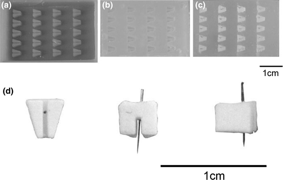
Formation of brushite cement anchors. (a) Wax mold produced by rapid prototyping. The wax mold is filled with silicone glue to produce (b) a silicone mold. (c) Cement paste spread into silicone mold and pin inserted into each anchor prior to cement paste setting. (d) Three views of cement anchor F [from below (without pin), back, and side]
Individual Anchor Formation
Minutien insect pins (Fine Science Tools, UK) were inserted into each silicone anchor mold before a newly mixed brushite cement paste was placed into the mold (Fig. 1c). The paste-filled molds were spun at 3700 rpm for 15 s inside a sealed plastic box on a swinging bucket rotor (A-2-DWP, Eppendorf 5804) to improve mold filling. All anchors were then left at room temperature overnight and individual anchors were removed from the mold the following day (Fig. 1d) and stored at room temperature until used.
To enhance the acuity of the casting process, several alterations were made to the cement/acid components. These included reducing the P:L and the molarity of OA, as well as the addition of 50 mM citric acid, a known cement setting retardant,4,5,30 and cement liquefier13 to the OA prior to combination with β-TCP. The effects of modifying the cement composition were assessed by studying their attachment longevity using rectangular-shaped anchors (see Tissue attachment in Methods section).
Cement Characterization
Compositional Characterization
To determine the crystalline composition of the brushite cement, the cement was powdered and mounted between two pieces of a magic tape in an X-ray diffractometer (D5005, Siemens, Germany). X-ray powder diffraction data were collected from 2θ = 10–70° with a step size of 0.02° and a normalized count time of 1 s/step using Cu Kα1 radiation. Diffraction patterns were compared with those from the JCPDS database. Since the major components of the set cement and the reactants of the brushite cement were confirmed as brushite (ρ = 2.32 g/cm3) and β-TCP (ρ = 3.09 g/cm3) with contrasting densities (see Fig. 2), it was possible to determine the degree of conversion of the β-TCP to brushite by measuring the true density of the powdered set cement.
FIGURE 2.
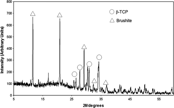
X-ray diffraction pattern of cement samples. Image confirms that only two phases are present within the set cement matrix, β-TCP (○) and brushite (△)
Density Measurements
True density (ρt) was determined using a helium pycnometer (Accupyc II 1340, Micromeritics, Georgia, USA) with ten measurements, following ten purges with helium (Air products, Birmingham, UK). Four samples were measured and the resulting values were the mean of 40 measurements. Apparent density (ρa) measurements were obtained using geometrical measurements and used to calculate relative porosity of the samples (Table 1).
Table 1.
Effect of molarity of OA on brushite cement properties
| Acid concentration (M) | Composition (wt.%) | Porosity (%) | Compressive strength (MPa) | |
|---|---|---|---|---|
| β-TCP | Brushite | |||
| 3.5 | 28 | 72 | 45 | 20.9 ± 3.2+ |
| 3 | 47 | 53 | 45 | 13.4 ± 3.4* |
| 2.5 | 57 | 43 | 50 | 11.1 ± 1.1* |
| 2 | 52 | 48 | 47 | 7.0 ± 1.1 |
*Significantly higher than 2 M, + significantly greater than all other molarities (p < 0.05; n = 6)
Mechanical Properties
Cylindrical cement samples (n = 6) of 12 mm height and 6 mm diameter were tested in compression using a Zwick/Roell Z030 (Leominster, UK). Samples were tested in axial compression at a crosshead speed of 1 mm/min using a 30-kN load cell. Maximum compressive strength (MPa) was calculated from the maximum force at failure, divided by cross-sectional area.
Ligament Formation
35-mm Petri dishes were coated with 1.5 mL of Sylgard (type 184 silicone elastomer, Dow Corning Corporation, Midland, MI, USA) and left to polymerize for at least a week prior to use. Cement anchors were pinned to the sylgard layer approximately 12 mm apart and the anchors and plate were sterilized by soaking in 70% ethanol for 20 min. 500 μL of F12 Hams media (Invitrogen, Paisley, UK) supplemented with 20% fetal bovine serum, 1% ABAM (Antibiotic/antimycotic, Invitrogen, UK), 50 U/mL thrombin (Calbiochem), 400 μM aminohexanoic acid (Sigma-Aldrich, UK), and 20 μg/mL aprotinin (Roche, UK) solution was used to coat the sylgard layer. 200 μL of 20 mg/mL fibrinogen (Sigma-Aldrich, UK) was then added dropwise and the fibrin gel was left to polymerize at 37 °C for 1 h. Primary tendon fibroblasts were isolated from the Achilles tendon of five rats by an overnight digestion in 0.1% type II collagenase dissolved in supplemented F12 Hams media at 37 °C. Fibroblasts were cultured and split routinely and used between passage 2 and 5. For the sinews, cells were seeded on top of the polymerized fibrin gel at a concentration of 100 K/mL. Growth media was replenished on day 3 following seeding, and then every second day for the duration of the experiments. Over time, the fibrin gel contracts around the two brushite cement anchors (Figs. 3a–3c) to form a cement–fibrin–cement (bone–ligament–bone) construct.
FIGURE 3.
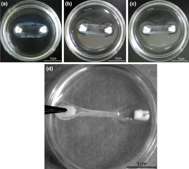
Formation and testing of brushite cement anchor/tissue interface. Tissue-engineered ligament formation with cell-seeded fibrin gel and brushite cement anchors (a) 3 days, (b) 5 days, (c) 7 days after plating as the fibrin gel contracts around the two cement anchor points. (d) Testing cement anchor/fibrin attachment. Cement anchor was lifted off the sylgard layer by the embedded pin. Attachment was scored as attached (as shown) or not attached if the soft tissue detached from the cement anchor
Cement Anchor/Fibrin Interface
Interface Longevity
The attachment of the cement anchor to the soft tissue was assessed by manually removing one anchor from the plate, every 3 days, and observing whether the soft tissue remained attached (Fig. 3d). Attachment was scored on a binary scale as attached/not attached. The effect of cement composition on interface longevity was studied using prism-shaped anchors with differing molarities of OA (Fig. 4a), increasing P:Ls (Fig. 4b) and the addition of citric acid to OA prior to combination with the β-TCP (Fig. 4c) for n = 5 per group. To assess the effect of anchor shape and surface area on interface longevity, ten anchor shapes were designed and manufactured (Figs. 5a–5j) and their interface longevity was monitored as described (n = 10). Shapes E–J were based on a prism shape that allowed the constructs to be easily gripped for mechanical testing.
FIGURE 4.
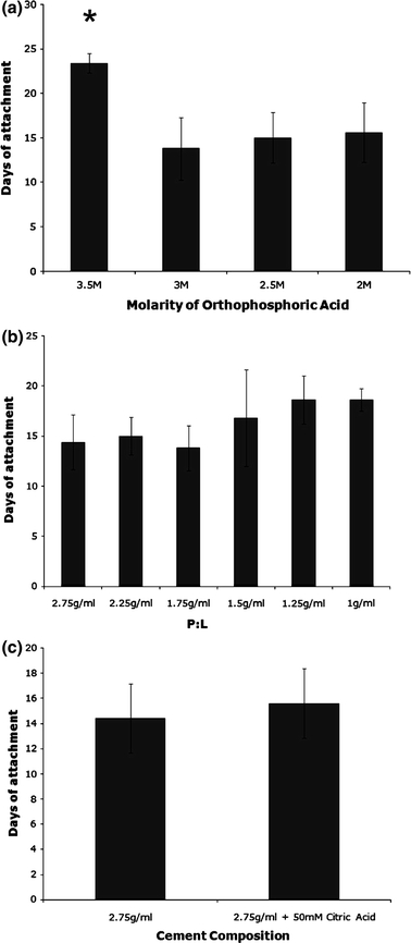
Effect of modifying cement composition on anchor attachment. (a) The effect of changing the molarity of OA used at a P:L of 2.75 g/mL; (b) changing the P:L at a molarity of 3.5 M OA, or (c) addition of 50 mM citric acid to 3.5 M OA on attachment time at a P:L of 2.75 g/mL. Results are presented as mean ± SEM of n = 5 for all sample types
FIGURE 5.
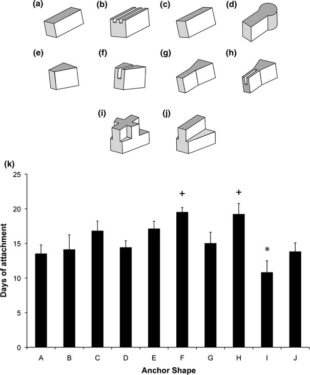
Effect of brushite anchor shape on interface longevity. (a–j) Scale drawings of ten anchor shape designs used for attachment study. Note that the images are inverted, i.e., top surfaces are surfaces in contact with the fibrin gel layer during formation. (k) Comparison of attachment time for all ten anchor shapes. Results are presented as mean ± SEM of n = 10 for all shapes. Plus mark indicates significantly longer and asterisk indicates significantly shorter attachment time (p < 0.05)
Interface Strength
Individual constructs (cement–fibrin–cement) were mechanically loaded to determine the strength of the soft-hard tissue interface. Mechanical tests were conducted using a custom built mechanical tester, adapted from a design described in Larkin et al. 24 (Figs. 6A and 6B). Grips to enable mechanical testing were manufactured as the inverse of the cement anchor shape using rapid prototyping technology (Spectrum Z510, Z Corp., Boston, USA). The mechanical tester was designed to allow the specimen to be immersed in saline solution throughout the testing procedure (Fig. 6Bi). To test the mechanical interface, the cement anchors were inverted and inserted into the grips (Fig. 6Bi). Care was taken to assure that the soft tissue was not in contact with any part of the grips, so that the recorded values represented interfacial stress and not the mechanical properties of the soft tissue portion. One grip was attached to a custom built force transducer,11 while the other was attached to a stepper motor (Fig. 6A). Immediately prior to the test, specimen dimensions were determined using a digital calliper. Using LabVIEW (National Instruments, Austin, TX), the sample was loaded at a constant rate of elongation of 0.4 mm/s and the resulting force was measured. Ultimate stress at the interface was calculated using the surface area available for attachment for each anchor shape for E, G, and H (n = 10) and F, and I (n = 8). Interface stress was also assessed using cement anchors formed at a variety of P:Ls (Fig. 7a) of 1 (n = 9), 3 (n = 5), 4 (n = 12), and 4.5 g/mL (n = 12). As a follow-up, the high and low P:L samples were studied over time (Fig. 7b). For these experiments, samples with a P:L ratio of 1 and 4 g/mL were studied at 1 week (1 g/mL—n = 9; 4 g/mL—n = 12), and 4 weeks (1 g/mL—n = 9; 4 g/mL—n = 7).
FIGURE 6.
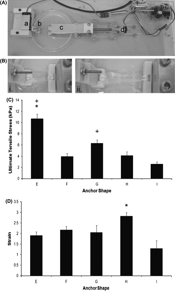
Functional analysis of the cement anchor/fibrin interface. (A) Custom built mechanical tester used to assess interface strength. (a) Force transducer, (b) shaped grip, (c) moving grip, and (d) stepper motor. (B) Testing mechanical properties of the cement anchor/fibrin interface. (i) Ligament construct placed upside down into grips prior to testing, (ii) ligament construct undergoing mechanical test. Tissue can be seen detaching from the right-hand side cement anchor. (C) Ultimate tensile stress and (D) maximum strain values for the anchor shapes E, F, G, H, and I. Results are presented as mean ± SEM for n = 10 (E, G, H) and n = 8 (F, I). Asterisk indicates significantly higher than all other shapes, whereas plus symbol indicates significantly higher than shape I (p < 0.05)
FIGURE 7.
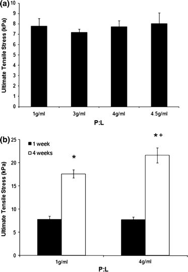
Effect of increasing P:L on interface strength. (a) The effect of different P:L on interface strength following 1 week in culture. Results are presented as mean ± SEM of n = 9 (1 g/mL), 5 (3 g/mL), 12 (4 g/mL), and 7 (4.5 g/mL). (b) Comparison of interface strengths at 1 and 4 weeks in culture. Results are presented as mean ± SEM of n = 9 (1 g/mL; 1 week), 12 (4 g/mL; 1 week), 9 (1 g/mL; 4 weeks), and 7 (4 g/mL; 4 weeks). Asterisk indicates significantly higher than at 1 week, whereas plus symbol indicates significantly higher than 1 g/mL (p < 0.05)
Statistical Analysis
Data are presented as means ± SEM unless stated otherwise. Differences in mean values were compared within groups and significant differences were determined by ANOVA with post hoc Tukey–Kramer HSD test using www.Brightstat.com. The significance level was set at p < 0.05.
Results
Varying Cement Anchor Composition
Various modifications were made to increase the setting time of the cement paste in order to provide better replication of the silicone anchor molds. Such measures included altering the concentration of OA, changing the P:L (β-TCP:OA), and adding 50 mM citric acid to the OA prior to mixing with β-TCP. Reducing OA concentration from 3.5 to 3 M led to a significant reduction in interface longevity from 23 ± 1 to 14 ± 4 days (Fig. 4a). This decrease was not observed through further reductions in OA molarity. The decrease in attachment was associated with less conversion of β-TCP to brushite and decreased compressive strength, with the 3.5 M OA group showing significantly higher brushite composition and compressive strength than all other groups (Table 1).
Altering the P:L of cement anchors does not significantly alter interface longevity (Fig. 4b). However, a trend is seen toward an increase in attachment time with decreasing P:L. Incorporating citric acid into OA prior to combination with β-TCP increased working time and reduced cement paste viscosity, but did not affect the longevity of the cement/fibrin interface (Fig. 4c).
Modifying Anchor Shape
Ten different anchor shapes were designed to establish whether anchor shape or anchor surface area was a key factor in determining cement anchor/fibrin interface longevity (Figs. 5a–5j). A mean attachment time of 15 ± 5 days was calculated across all groups; however, it is clear that shapes C, E, F, and H perform well above this mean value. Notably, there was a significant effect of introducing a single groove into a solid block anchor, as is demonstrated by comparing shapes E to F and shape G to H (Fig. 5k). Furthermore, introducing complex shapes and angles into the anchor design has a detrimental effect on interface longevity (shape I, Fig. 5). To establish whether there was a significant effect of surface area on interface longevity, three separate values for the surface area of the anchors were calculated for each shape. Neither the surface area of the whole anchor, the surface area without the top anchor surface (never in contact with the tissue portion), nor the interface area in contact with the tissue portion showed a correlation with tissue attachment time (Table 2).
Table 2.
Surface area (SA) calculations for each anchor shape
| Anchor shape | A | B | C | D | E | F | G | H | I | J | R 2 |
|---|---|---|---|---|---|---|---|---|---|---|---|
| Total SA (mm2) | 48.0 | 55.4 | 41.3 | 42.3 | 53.3 | 63.3 | 85.8 | 96.3 | 54.0 | 49.4 | 0.19 |
| SA without top (mm2) | 380 | 45.4 | 33.7 | 34.9 | 44.6 | 54.6 | 71.8 | 82.3 | 45.3 | 40.7 | 0.21 |
| Interface SA (mm2) | 10.0 | 18.0 | 7.6 | 7.6 | 8.8 | 19.3 | 14.0 | 25.3 | 20.8 | 19.3 | 0.01 |
Functional Analysis of the Cement Anchor/Fibrin Interface
The strength of the cement anchor/fibrin interface was tested 7 days after plating using the best attaching (shapes F and H) and their corresponding lower surface area shapes (shapes E and G) as well as the poorest attaching shape (shape I). Mean values for maximum load and extension at failure are presented in Table 3.
Table 3.
Maximum load and extension values for five anchor shapes
| Anchor shape | |||||
|---|---|---|---|---|---|
| E | F | G | H | I | |
| Max. load (mN) | 59 ± 30* | 31 ± 10 | 51 ± 40 | 52 ± 30* | 20 ± 23 |
| Extension (mm) | 26.5 ± 7.43 | 18.2 ± 2.95 | 27.0 ± 13.43 | 29.0 ± 5.87 | 16.7 ± 13.32 |
*Significantly greater than anchor shape I (p < 0.05)
Unlike the data collected for attachment time, anchor shape E performed the best under load, reaching values of 59 ± 30 mN, although this only reaches statistical significance when compared to anchor shape I (p = 0.013; Table 3). Similarly, anchor shape H displayed significantly higher values for maximum load when compared to anchor I (p = 0.019; Table 3). Extension distances at failure remained similar between all anchor shapes, with no significant difference observed between anchor shapes (p > 0.05 in all cases; Table 3). To evaluate the effect of anchor shape and/or surface area on interface strength, the stress at the anchor/tissue interface was calculated for each anchor shape, based on surface area available for attachment. Similar to the data for maximum load, anchor shape E performed the best under mechanical stress, withstanding stresses of 9.5 ± 1.6 kPa before interface failure (Fig. 6C), which proved significantly higher than all other anchor shapes (p < 0.001). The ultimate stress for the corresponding high surface area anchor (shape F) was 3.3 ± 0.7 kPa, less than half of the corresponding low surface area anchor (shape E; Fig. 6C). A similar trend existed when comparing shapes G and H, with stresses of 6.3 ± 0.6 and 4.1 ± 0.7 kPa, respectively (Fig. 6C). Under all conditions, shape I was the worst performing anchor in terms of interface longevity and strength, withstanding stresses of 2.6 ± 0.4 kPa (Fig. 6C). Maximum strain at failure values for all anchors do not differ significantly between shapes, except for a significant difference between anchor shapes H and I (p = 0.002) (Fig. 6D).
Strength of the cement/fibrin interface was assessed using several different P:L to determine the effect of P:L on the ability of the interface to withstand stress. At 7 days after plating, increasing the P:L had no effect on the strength of the interface, with a mean value of 7.8 ± 0.4 kPa observed across all groups (Fig. 7a). 4 weeks after plating, the strength of the interface was significantly higher at both high and low P:L when compared with the 1 week values, with ultimate stresses at the interface reaching 17.6 ± 0.9 kPa (p < 0.001) and 21.6 ± 1.6 kPa (p < 0.001; Fig. 7b). Furthermore, a positive effect of the higher P:L is seen at the 4-week time point where the ultimate tensile stress of 4 g/mL cement anchor interface was significantly higher (p = 0.034) when compared to 1 g/mL (Fig. 7b).
Discussion
The aim of this study was to determine the factors that control the strength and longevity of the interface between brushite cement and a fibrin-based sinew. Several material and morphological adaptations were identified that regulated longevity and strength of the in vitro cement–ligament interface, including varying the composition, shape, and surface area of the brushite cement anchors.
Spalazzi et al. 31,32 have described the fabrication of an in vitro scaffold to mimic an in vivo interface. Their triphasic scaffold physically mimics the fibrocartilaginous transition seen at the native insertion site. Although this work has produced an elegant fibrocartilaginous transition,31 neither the tensile properties of the scaffold nor the attachment potential with hard or soft tissues have been reported. Therefore, the biological potential of the scaffold, i.e., whether the scaffold provides a mechanically sound attachment between compliant and stiff tissues remains to be determined. Phillps et al. 29 have successfully reported the manufacture of a continuous bone–soft tissue interface using fibroblasts seeded onto a polymeric scaffold containing a gradient of runt-related transcription factor 2 (Runx2). Although graded mineral deposition and mechanics along the length of the construct were achieved using this technique, a fibrocartilaginous interface region was not formed, and therefore this model does not fully replicate the native bone–ligament insertion.
This study demonstrates that a functional cement–sinew interface can be engineered in vitro and that the longevity of this interface is dependant upon the conversion of β-TCP to brushite (Fig. 4a and Table 1) and the surface area more than stress/strain concentrations (Fig. 5k). The strength of the interface is dependant upon time in culture or collagen content (Fig. 7b) and stress/strain concentrations more than surface area. The maximum interface strength reported here (21.6 ± 1.6 kPa) is four orders of magnitude less than an adult tendon and three orders of magnitude less than neonatal tendon.7 However, we have achieved this interface in the absence of growth factors, high concentrations of ascorbic acid, and mechanical loading, all of which are know to increase collagen production and stiffness.1,23 Therefore, inclusion of these factors should improve the interface strength further.
There are numerous advantages to using a calcium phosphate cement to form a musculoskeletal interface. First, calcium phosphate cements are osteoconductive12; second, they are fast and easy to make with short setting times15,17; third they exhibit relatively high compressive strengths and are able to withstand loading immediately10; fourth they have similar chemical composition to that of endogenous bone12; fifth, they are known to increase the strength of attachment with biological tissues22,34; and sixth, certain calcium phosphate cements can be biologically resorbed over time.15,17
Since brushite cements are made via a simple powder (β-TCP) and liquid (OA) mixing reaction and are several orders of magnitude more resorbable than HA, they are an ideal calcium phosphate for engineering a bone anchor for an engineered sinew. Here, we described a simple reverse mold casting process to produce identical anchors of varying shapes and surface areas with a high degree of accuracy (Figs. 1 and 5). However, complex detailing with this method is difficult due to the resolution of the rapid prototyping machine used to print the thermoplastic molds, and the viscosity of the glue used to make the silicone mold. Although restricted by the manufacturing processes, ten different shapes were designed and utilized to determine the effect of shape and surface area on cement anchor attachment (Fig. 5). Even though no correlation was observed between the surface area of the cement anchors and the duration of tissue attachment, the addition of a single groove into solid cement anchor blocks led to an increase in attachment time (compare shapes E to F and shapes G to H, Fig. 5). Unlike the longevity tests, strength tests showed that anchor E could withstand much higher stresses than its corresponding high surface area shape, anchor F, and a similar pattern was observed between anchors G and H (Fig. 6). These data suggest that interface duration and strength are determined by the interplay between the positive effects of surface area and the negative effects of stress/strain concentrations and that the ideal anchor will have a high surface area and minimal areas of stress/strain concentrations.
Even though it is not possible to generate high surface area/minimal stress/strain anchors using reverse molding, brushite can be engineered with these properties using laser sintering35 or 3D powdered printing.14 Specifically, Gbureck et al. 14 showed that 3D powder printing could be used to engineer custom ceramic blocks of any shape. Combining their technique with the current work may result in high surface area, minimal stress/strain concentration cement anchors designed specifically to fit ligament fixation sites if these bone-to-bone–ligaments were to reach the clinic.
The attachment points of musculoskeletal tissues in vivo are graded structures, unlike the abrupt transition engineered here. However, although the osteoligamentous junction is a graded structure, there is a sharp transition in mineral content between the non-mineralized and mineralized fibrocartilage regions.27 This finding is encouraging for the paradigm described here for engineering a ligament, as the use of a solid block of brushite cement may not be as anatomically inappropriate as perhaps first perceived. The greatest challenge to continued development of this system is to modify the attachment point of the tissue to promote the formation of a fibrocartilaginous region, replicating the natural bone–ligament interface. To facilitate this, brushite cements can be manufactured to allow for the controlled release of growth factors from the cement matrix19,25 that may help to promote fibrocartilage formation.
Reducing the molarity of OA reduced cement paste viscosity; however, the highest molarity (3.5 M OA) showed a significantly longer attachment time when compared with all other molarities used (Fig. 4). This increase in attachment time is likely due to the higher degree of conversion of β-TCP to brushite within the cement matrix, and a significantly higher compressive strength at this molarity (Table 1). To further investigate the role of brushite content as the source of interface strength, it was hypothesized that increasing P:L of the cement anchors would lead to a stronger interface over time. Increasing the culture period increased the ultimate tensile stress of both groups (compared to their corresponding P:L at 1 week; Fig. 7b), likely due to an increase in collagen at the interface. We have previously noted an increase in collagen content of the sinews over time, from 1.45 ± 0.32% at 2 weeks of formation to 2.92 ± 0.18% at 4 weeks of formation (Paxton et al., submitted). As well as the positive effect of time, the ultimate tensile stress of the 4 g/mL cement anchor interface exceeded that of the 1 g/mL interface (Fig. 7b). From these data, it is clear that increasing brushite, or slowing its loss, increases the strength of the interface. However, interface failure cannot solely be attributed to brushite dissolution.
The results presented here demonstrate that brushite cement is a suitable material for engineering the bone–ligament interface in vitro. Brushite cement anchors adhere to our ligament constructs for 2–3 weeks when repeatedly tested and can remain attached for in excess of 3 months if the interface is left undisturbed in culture (Paxton et al., submitted). The maximum stress recorded before failure of the interface occurred after 4 weeks in culture was 21.6 kPa which is still lower than would be required if this graft was to be implanted. However, an encouraging finding is that both the length of attachment and the strength of this attachment can be enhanced by altering the physiochemical properties of the cement anchors themselves. Varying the P:L, anchor shape and surface area had significant effects on attachment time and interface strength but the modifications reported here are by no means exhaustive and it is thought that further modifications of the properties, shape, and degradation characteristics of the cement anchors could lead to improved interface longevity and strength. Such advances could project the relevance of this study toward the clinic as a potential method of engineering complete bone-to-bone–ligament grafts for implantation.
Acknowledgments
This study was supported by grants from the Engineering and Physical Sciences Research Council (EPSRC—EP/E008925/1) and the Biotechnology and Biological Sciences Research Council (BBSRC—BB/F002084/1).
Open Access
This article is distributed under the terms of the Creative Commons Attribution Noncommercial License which permits any noncommercial use, distribution, and reproduction in any medium, provided the original author(s) and source are credited.
References
- 1.Ando W, Tateishi K, Katakai D, Hart DA, Higuchi C, Nakata K, Hashimoto J, Fujie H, Shino K, Yoshikawa H, et al. In vitro generation of a scaffold-free tissue-engineered construct (TEC) derived from human synovial mesenchymal stem cells: biological and mechanical properties and further chondrogenic potential. Tissue Eng. A. 2008;14(12):2041–2049. doi: 10.1089/ten.tea.2008.0015. [DOI] [PubMed] [Google Scholar]
- 2.Benjamin M, Ralphs JR. Entheses—the bony attachments of tendons and ligaments. Ital. J. Anat. Embryol. 2001;106(2 Suppl 1):151–157. [PubMed] [Google Scholar]
- 3.Beynnon BD, Johnson RJ, Fleming BC, Kannus P, Kaplan M, Samani J, Renstrom P. Anterior cruciate ligament replacement: comparison of bone-patellar tendon-bone grafts with two-strand hamstring grafts. A prospective, randomized study. J. Bone Joint Surg. 2002;84-A(9):1503–1513. doi: 10.2106/00004623-200209000-00001. [DOI] [PubMed] [Google Scholar]
- 4.Bohner M, Lemaitre J, Ring T. Effects of sulphate, pyrophosphate, and citrate ions on the physiochemical properties of cements made from the β-tricalcium phosphate-phosphoric acid-water mixtures. J. Am. Ceram. Soc. 1996;79:1427–1434. doi: 10.1111/j.1151-2916.1996.tb08746.x. [DOI] [Google Scholar]
- 5.Bohner M, Merkle HP, Landuyt PV, Trophardy G, Lemaitre J. Effect of several additives and their admixtures on the physico-chemical properties of a calcium phosphate cement. J. Mater. Sci. Mater. Med. 2000;11(2):111–116. doi: 10.1023/A:1008997118576. [DOI] [PubMed] [Google Scholar]
- 6.Brand J, Jr, Weiler A, Caborn DN, Brown CH, Jr, Johnson DL. Graft fixation in cruciate ligament reconstruction. Am. J. Sports Med. 2000;28(5):761–774. doi: 10.1177/03635465000280052501. [DOI] [PubMed] [Google Scholar]
- 7.Calve, S., I. F. Lytle, K. Grosh, D. L. Brown, and E. M. Arruda. Implantation increases tensile strength and collagen content of self-assembled tendon constructs. J. Appl. Physiol. 108:875–881, 2010. [DOI] [PubMed]
- 8.Carmichael JR, Cross MJ. Why bone-patella tendon-bone grafts should still be considered the gold standard for anterior cruciate reconstruction. Br. J. Sports Med. 2009;43(5):232–235. doi: 10.1136/bjsm.2009.058024. [DOI] [PubMed] [Google Scholar]
- 9.Chang SK, Egami DK, Shaieb MD, Kan DM, Richardson AB. Anterior cruciate ligament reconstruction: allograft versus autograft. Arthroscopy. 2003;19(5):453–462. doi: 10.1053/jars.2003.50103. [DOI] [PubMed] [Google Scholar]
- 10.Charriere E, Terrazzoni S, Pittet C, Mordasini PH, Dutoit M, Lemaitre J, Zysset PH. Mechanical characterization of brushite and hydroxyapatite cements. Biomaterials. 2001;22(21):2937–2945. doi: 10.1016/S0142-9612(01)00041-2. [DOI] [PubMed] [Google Scholar]
- 11.Dennis RG, Kosnik PE. Mesenchymal cell culture: instrumentation and methods for evaluating engineered muscle. In: Atala A, Lanza R, editors. Methods in Tissue Engineering. San Diego: Harcourt, Academic Press; 2002. pp. 307–316. [Google Scholar]
- 12.Dorozhkin SV, Epple M. Biological and medical significance of calcium phosphates. Angew. Chem. Int. Ed. Engl. 2002;41(17):3130–3146. doi: 10.1002/1521-3773(20020902)41:17<3130::AID-ANIE3130>3.0.CO;2-1. [DOI] [PubMed] [Google Scholar]
- 13.Gbureck U, Barralet JE, Spatz K, Grover LM, Thull R. Ionic modification of calcium phosphate cement viscosity. Part I: hypodermic injection and strength improvement of apatite cement. Biomaterials. 2004;25(11):2187–2195. doi: 10.1016/j.biomaterials.2003.08.066. [DOI] [PubMed] [Google Scholar]
- 14.Gbureck U, Holzel T, Biermann I, Barralet JE, Grover LM. Preparation of tricalcium phosphate/calcium pyrophosphate structures via rapid prototyping. J. Mater. Sci. 2008;19(4):1559–1563. doi: 10.1007/s10856-008-3373-x. [DOI] [PubMed] [Google Scholar]
- 15.Grover LM, Gbureck U, Wright AJ, Tremayne M, Barralet JE. Biologically mediated resorption of brushite cement in vitro. Biomaterials. 2006;27(10):2178–2185. doi: 10.1016/j.biomaterials.2005.11.012. [DOI] [PubMed] [Google Scholar]
- 16.Grover LM, Hofmann MP, Gbureck U, Kumarasami B, Barralet JE. Frozen delivery of brushite calcium phosphate cements. Acta Biomater. 2008;4(6):1916–1923. doi: 10.1016/j.actbio.2008.06.003. [DOI] [PubMed] [Google Scholar]
- 17.Grover LM, Knowles JC, Fleming GJ, Barralet JE. In vitro ageing of brushite calcium phosphate cement. Biomaterials. 2003;24(23):4133–4141. doi: 10.1016/S0142-9612(03)00293-X. [DOI] [PubMed] [Google Scholar]
- 18.Gulotta LV, Rodeo SA. Biology of autograft and allograft healing in anterior cruciate ligament reconstruction. Clin. Sports Med. 2007;26(4):509–524. doi: 10.1016/j.csm.2007.06.007. [DOI] [PubMed] [Google Scholar]
- 19.Hofmann MP, Mohammed AR, Perrie Y, Gbureck U, Barralet JE. High-strength resorbable brushite bone cement with controlled drug-releasing capabilities. Acta Biomater. 2009;5(1):43–49. doi: 10.1016/j.actbio.2008.08.005. [DOI] [PubMed] [Google Scholar]
- 20.Kartus J, Movin T, Karlsson J. Donor-site morbidity and anterior knee problems after anterior cruciate ligament reconstruction using autografts. Arthroscopy. 2001;17(9):971–980. doi: 10.1053/jars.2001.28979. [DOI] [PubMed] [Google Scholar]
- 21.Kartus J, Stener S, Lindahl S, Engstrom B, Eriksson BI, Karlsson J. Factors affecting donor-site morbidity after anterior cruciate ligament reconstruction using bone-patellar tendon-bone autografts. Knee Surg. Sports Traumatol. Arthrosc. 1997;5(4):222–228. doi: 10.1007/s001670050054. [DOI] [PubMed] [Google Scholar]
- 22.Kitsugi T, Yamamuro T, Nakamura T, Kotani S, Kokubo T, Takeuchi H. Four calcium phosphate ceramics as bone substitutes for non-weight-bearing. Biomaterials. 1993;14(3):216–224. doi: 10.1016/0142-9612(93)90026-X. [DOI] [PubMed] [Google Scholar]
- 23.Kjaer M. Role of extracellular matrix in adaptation of tendon and skeletal muscle to mechanical loading. Physiol. Rev. 2004;84(2):649–698. doi: 10.1152/physrev.00031.2003. [DOI] [PubMed] [Google Scholar]
- 24.Larkin LM, Calve S, Kostrominova TY, Arruda EM. Structure and functional evaluation of tendon-skeletal muscle constructs engineered in vitro. Tissue Eng. 2006;12(11):3149–3158. doi: 10.1089/ten.2006.12.3149. [DOI] [PMC free article] [PubMed] [Google Scholar]
- 25.Le Nihouannen D, Hacking SA, Gbureck U, Komarova SV, Barralet JE. The use of RANKL-coated brushite cement to stimulate bone remodelling. Biomaterials. 2008;29(22):3253–3259. doi: 10.1016/j.biomaterials.2008.03.035. [DOI] [PubMed] [Google Scholar]
- 26.Mastrokalos DS, Springer J, Siebold R, Paessler HH. Donor site morbidity and return to the preinjury activity level after anterior cruciate ligament reconstruction using ipsilateral and contralateral patellar tendon autograft: a retrospective, nonrandomized study. Am. J. Sports Med. 2005;33(1):85–93. doi: 10.1177/0363546504265926. [DOI] [PubMed] [Google Scholar]
- 27.Moffat KL, Sun WH, Pena PE, Chahine NO, Doty SB, Ateshian GA, Hung CT, Lu HH. Characterization of the structure-function relationship at the ligament-to-bone interface. Proc. Natl Acad. Sci. 2008;105(23):7947–7952. doi: 10.1073/pnas.0712150105. [DOI] [PMC free article] [PubMed] [Google Scholar]
- 28.Paxton JZ, Donnelly K, Keatch RP, Baar K. Engineering the bone-ligament interface using polyethylene glycol diacrylate incorporated with hydroxyapatite. Tissue Eng. 2009;15(6):1201–1209. doi: 10.1089/ten.tea.2008.0105. [DOI] [PubMed] [Google Scholar]
- 29.Phillips JE, Burns KL, Le Doux JM, Guldberg RE, Garcia AJ. Engineering graded tissue interfaces. Proc. Natl Acad. Sci. USA. 2008;105(34):12170–12175. doi: 10.1073/pnas.0801988105. [DOI] [PMC free article] [PubMed] [Google Scholar]
- 30.Sarda S, Fernandez E, Nilsson M, Balcells M, Planell JA. Kinetic study of citric acid influence on calcium phosphate bone cements as water-reducing agent. J. Biomed. Mater. Res. 2002;61(4):653–659. doi: 10.1002/jbm.10264. [DOI] [PubMed] [Google Scholar]
- 31.Spalazzi JP, Dagher E, Doty SB, Guo XE, Rodeo SA, Lu HH. In vivo evaluation of a multiphased scaffold designed for orthopaedic interface tissue engineering and soft tissue-to-bone integration. J. Biomed. Mater. Res. A. 2008;86(1):1–12. doi: 10.1002/jbm.a.32073. [DOI] [PubMed] [Google Scholar]
- 32.Spalazzi JP, Doty SB, Moffat KL, Levine WN, Lu HH. Development of controlled matrix heterogeneity on a triphasic scaffold for orthopedic interface tissue engineering. Tissue Eng. 2006;12(12):3497–3508. doi: 10.1089/ten.2006.12.3497. [DOI] [PubMed] [Google Scholar]
- 33.Tomita F, Yasuda K, Mikami S, Sakai T, Yamazaki S, Tohyama H. Comparisons of intraosseous graft healing between the doubled flexor tendon graft and the bone-patellar tendon-bone graft in anterior cruciate ligament reconstruction. Arthroscopy. 2001;17(5):461–476. doi: 10.1053/jars.2001.24059. [DOI] [PubMed] [Google Scholar]
- 34.Wen CY, Qin L, Lee KM, Chan KM. The use of brushite calcium phosphate cement for enhancement of bone-tendon integration in an anterior cruciate ligament reconstruction rabbit model. J. Biomed. Mater. Res. 2009;89(2):466–474. doi: 10.1002/jbm.b.31236. [DOI] [PubMed] [Google Scholar]
- 35.Wilson CE, de Bruijn JD, van Blitterswijk CA, Verbout AJ, Dhert WJ. Design and fabrication of standardized hydroxyapatite scaffolds with a defined macro-architecture by rapid prototyping for bone-tissue-engineering research. J. Biomed. Mater. Res. A. 2004;68(1):123–132. doi: 10.1002/jbm.a.20015. [DOI] [PubMed] [Google Scholar]
- 36.Xia Z, Grover LM, Huang Y, Adamopoulos IE, Gbureck U, Triffitt JT, Shelton RM, Barralet JE. In vitro biodegradation of three brushite calcium phosphate cements by a macrophage cell-line. Biomaterials. 2006;27(26):4557–4565. doi: 10.1016/j.biomaterials.2006.04.030. [DOI] [PubMed] [Google Scholar]


