Abstract
The goal of this work is to develop a novel, accurate, real-time digital baseline restorer using online statistical processing for a high count-rate digital system such as positron emission tomography (PET). In high count-rate nuclear instrumentation applications, analog signals are DC-coupled for better performance. However, the detectors, pre-amplifiers and other front-end electronics would cause a signal baseline drift in a DC-coupling system, which will degrade the performance of energy resolution and positioning accuracy. Event pileups normally exist in a high-count rate system and the baseline drift will create errors in the event pileup-correction. Hence, a baseline restorer (BLR) is required in a high count-rate system to remove the DC drift ahead of the pileup correction. Many methods have been reported for BLR from classic analog methods to digital filter solutions. However a single channel BLR with analog method can only work under 500 kcps count-rate, and normally an analog front-end application-specific integrated circuits (ASIC) is required for the application involved hundreds BLR such as a PET camera. We have developed a simple statistics-based online baseline restorer (SOBLR) for a high count-rate fully digital system. In this method, we acquire additional samples, excluding the real gamma pulses, from the existing free-running ADC in the digital system, and perform online statistical processing to generate a baseline value. This baseline value will be subtracted from the digitized waveform to retrieve its original pulse with zero-baseline drift. This method can self-track the baseline without a micro-controller involved. The circuit consists of two digital counter/timers, one comparator, one register and one subtraction unit. Simulation shows a single channel works at 30 Mcps count-rate with pileup condition. 336 baseline restorer circuits have been implemented into 12 field-programmable-gate-arrays (FPGA) for our new fully digital PET system.
Index Terms: Auto-calibration, baseline restoration, FPGA, positron emission tomography (PET)
I. Introduction
As the digital techniques become more popular and powerful, the typical analog processing features such as the pole-zero compensation, pulse shaper, baseline restorer and anti-aliasing filter can be digitally implemented and optimized. The purpose of this study is to develop a simple digital baseline restorer for a high count-rate fully digital system such as a digital PET camera.
Many baseline-restoration approaches have been reported from classic analog methods [1]–[3] to digital filter solutions [4]–[6]. However the accuracy of baseline restoration drops rapidly at high count-rate condition with event-pileups especially in an analog AC coupling system.
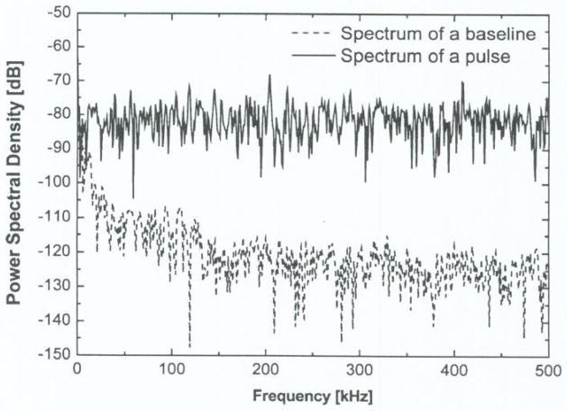
A traditional feedback baseline restorer (BLR) provides a quick baseline restoration before the arrival of the next pulse and requires a large bandwidth for responding to each pulse [1]–[4]. Like a high-pass filter the feedback BLR cannot restore a slow-drifting baseline, it normally requires a gating signal and an ac-coupling. It is well known, that ac-coupling in front-end will exhibit a baseline shift as the rate of pulses increases. Normally, a baseline drift caused by thermal drifts, power-line disturbances, hum, etc. is a relatively slow movement; hence to retrieve a baseline accurately, a good BLR should deal with a large time period involving many pulses, not just a single one. A feedback BLR based on a single pulse using either a low-pass filter or a high-pass filter is sensitive to pileup and noise conditions. This also can be confirmed by the power spectra of pulses and the baseline as shown in Fig. 1. The main part of baseline’s power spectrum is in a low frequency domain (below 100 kHz) while the pulse’s power spectrum is equally distributed over the entire frequency domain; hence a simple low-pass filter cannot easily separate the baseline from the mixed signals without distorting the pulses.
Fig. 1.
Comparison of a baseline’s power spectrum and pulse’s power spectrum.
An alternate feedback design for baseline restorer is called baseline holder (BLH) [7], [8]. The BLH is a stage, which compares the output voltage of the channel to a reference voltage and, after applying a low-pass filter, feeds the signal back to the input of the shaper amplifier. The BLH does not require a gating signal. The drawback of the BLH is that it cannot separate the residual fluctuation caused by event-pileup from the environment related baseline drift. Therefore, for high event-rate applications both baseline feedback methods are handicapped.
This paper presents a method of statistics-based online baseline restorer (SOBLR) for a high count-rate fully digital system that can compensate for the environment caused baseline drift but not for the event-pileup caused drift.
II. Methods
A. Essential Baseline Stabilization for PET
The baseline instabilities and fluctuations due to thermal drifts, power-line disturbances, hum and ac couplings, degrade substantially the energy and positioning accuracy in nuclear event detection. Additional to that, a PET camera has a long acquisition time, a large electronics scale and a large count-rate range that all require good baseline stabilization. With the advent of semiconductor photo-detectors, potentially applicable to large PET systems, the leakage current may also cause a wide range of baseline drift.
In a conventional PET camera, there are hundreds BLR channels integrated in the front-end CMOS application-specific integrated circuits (ASIC) to compensate for count-rate dependent baseline drifts due to ac-coupling and for the accumulated CMOS dc-offsets in the signal processing channels [9], [10]. The pulse height output from each gated integrator is stable for count-rates of 10–100 kcps but it has a 5% drop at a count-rate of 500 kcps [10]. The output drop will accelerate with the count-rate exceeding 500 kcps. In addition to this count-rate issue, this ASIC BLR only corrects the upstream baseline shift from the detector to ASIC, not the downstream shift from ASIC to ADC’s conditional circuits.
In high-resolution PMT-quadrant-sharing (PQS) position-sensitive PET block detectors [11], [12] that we have been working with for many years, one PMT channel involves a large decoding area of four detector blocks, which increases the count-rate for each channel. Our high light-output PQS detectors have a large decoding ratio of 256 crystals/PMT for LYSO (4 to 15 times higher decoding resolution than that of current PET manufacturers). This high-resolution detector position-decoding requires a high accuracy of light-distribution measurement. Hence, a better baseline restorer is essential for this high decoding resolution and high count-rate PQS PET detectors.
We also have introduced a high-yield pileup-event recovery (HYPER) method to correct the pileups for a high count-rate DC coupling system [13], [14]. The main parts of HYPER method are dynamic integration and remnant signal correction, and both require the signal’s baseline to be set strictly to ground level.
B. Data Collection for Statistics-Based Online Baseline Restorer
Hundreds or even thousands of low-cost fast free-running ADCs, widely used by digital communication, are adopted in one PET camera [15], [16]. The front-end digital processing unit of PET only applies to the ADC’s samplings for pulses that are enabled by the event trigger to get the energy and position information. Most of ADC’s samplings (more than 80%) are not related to the pulses and are discarded by the processing unit. This study is to use these (non-event) ADC data to restore the baseline. Since the data are picked up from the ADC’s output, the baseline drift caused from the upstream detector signal all the way to the input of ADC will be corrected for. In this method it tracks the baseline first and then subtracts baseline result from the digitized pulse by a digital processing unit, without any analog feedback circuits used by a traditional BLR. Hence, this method will be more accurate at baseline restoration and significantly lower the electronics cost and reduce the power consumption and electronics noise.
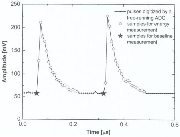
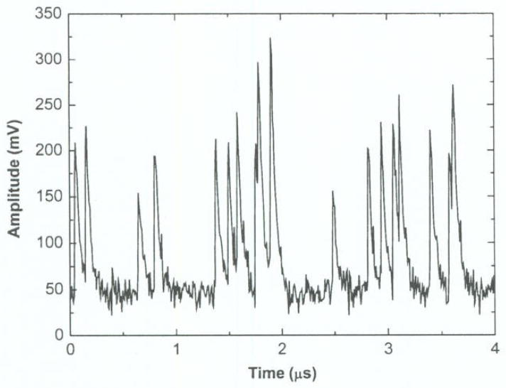
Fig. 2 shows the ADC samplings acquired for the pulse and the baseline restorer. The baseline sampling is picked up right before the pulse triggering; hence this pre-trigger data only samples the baseline excluding the pulse. Only one pre-trigger sample of each event is acquired from the free-running ADC. A simple digital register buffering the ADC output can realize this pre-trigger sampling. When an event trigger occurs the output of this register stores the pre-trigger data for baseline tracking. If a pulse’s rise-time is slow, to avoid the rising edge of the pulse, extra registers/buffers may be required to catch an earlier sample as the baseline data.
Fig. 2.
Digital samplings for the pulse and the digital baseline restorer from a free-running ADC output.
C. Histogram of Baseline Samples
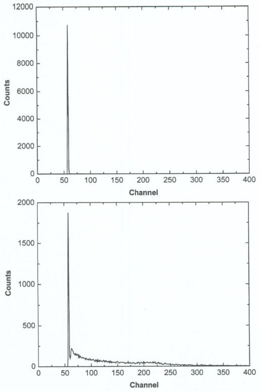
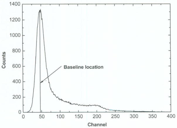
The above baseline sample is not the final baseline output even though it excludes the signal of the coming pulse. Since this baseline sample could be affected by the noise and the residual signals from all the previous pileups, a baseline restorer based on such a single sample would still be count-rate dependent. To find the true baseline value, we did a histogram of those baseline samples, shown in Fig. 3. The peak location of the histogram identifies the true baseline that is less sensitive to the count-rate and noise. Fig. 3 shows that the count-rates of 100 kcps and 10 000 kcps have the same baseline peak location in the histograms of the pre-trigger samples.
Fig. 3.
Baseline histogram of pre-trigger samples with a fixed accumulated number of counts. Upper: at 100 kcps rate; bottom: at 10000 kcps rate with high pileup condition.
Baseline samples mixed by the residual signals from pileups are larger signals and are put into higher-than-peak channels as shown in the bottom graph of Fig. 3, but it does not change the baseline peak location. Random noise widens the baseline-peak but will not change the peak location. Hence, unlike the traditional feedback BLR using a single pulse, the baseline value retrieved from this histogram involving many pulses (one baseline sample per pulse) and neither the noise nor the count-rate can affect its peak location. By excluding the pulse from the baseline sample, the baseline peak in the histogram can be easily identified from the pileup channels (the channels higher than the baseline peak) even at a very high count-rate up to 30 Mcps. Since the baseline sample with residual pileups spreads to many high-channels while all the “pure” baseline samples with no pileup are accumulated in a single channel forming the peak, hence the baseline-peak will be easily separated from other channels. Similar to a medium filter, detecting the peak in the histogram ignores all other “noise” channels.
According to the Poisson probability distribution function, the number of events occurring within a given time interval can be modeled by:
| (1) |
where x is the number of events occurring within a given time interval, and λ is the shape parameter which indicates the average number of events in the given time interval.
As has been discussed earlier, the peak in the baseline histogram comes from the “pure” baseline samples with no pileup-residual signal added. Hence, the probability of this non-pileup baseline peak (x = 0 in (1)) occurring within a given time interval is e−λ. For an example, a pulse from a LYSO detector has a 40 ns decay constant, and if no pulse is observed within 200 ns (five times of decay constant) ahead of a baseline sample, this baseline sample would be counted as no pileup baseline. For a count-rate of 1 000 kcps, a 200 ns time period will have an expectation value (λ) of 0.2 pulse, and the probability of zero event (non-pileup baseline sample) is 81.87%, according to the Poisson probability distribution function. In other words, an 81.87% of the total baseline samples will be accumulated in the baseline-peak channel, which could be easily identified. The baseline peak even at a pulse rate of 10 000 kcps is still nice and sharp as shown in the bottom graph of Fig. 3.
D. A Simple Approach for the Statistics-Based Online Baseline Restorer
After finishing one baseline histogram for pre-defined period, a processing unit will find one baseline code (the peak location) and put it into a buffer, and this code will be subtracted from the digitized waveform samplings to retrieve its original pulse with zero-baseline drift. The histogram will then be cleared and ready for next baseline tracking period. For the period of one histogram acquisition time only one baseline-code is generated, hence the SOBLR does not instantaneously update the baseline code. For a pulse rate of 1000 kcps, a histogram of 1000 baseline samples takes 1 ms. Therefore in this case SOBLR will track the baseline in every millisecond. This millisecond tracking speed is acceptable for a slow baseline movement.
In order to do a histogram and to search for its peak location, a traditional way using FPGA requires some on-chip memory blocks to store the histogram and some logic blocks for real-time updating of the histogram and to search for the peak location and then clear the memory after finishing the histogramming. With this traditional design, tens of SOBLR channels would allocate most of the FPGA’s memory blocks (maximum on-chip memory space of one FPGA is a few Mbits). Hence, it would be impossible to fit other PET functions together with this traditional approach. Therefore we have developed a simpler approach for the baseline restorer as described below.
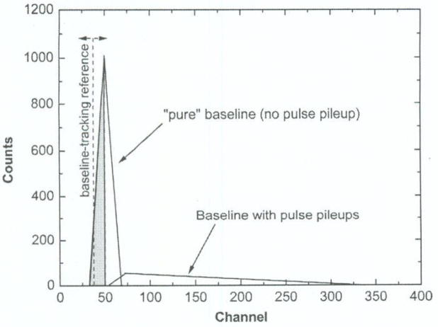
As shown in Fig. 4, a baseline spectrum is consisted of the spectrum of a “pure” baseline (Gaussian-shaped) and a spread baseline with pileup-residual signal added. In an ideal case the spread baseline spectrum is located in the right side of the baseline-peak. Assume P0 is the Poisson distribution probability of the “pure” baseline with no pulse pileup, hence the probability a “pure” baseline sample assigned to the left of baseline-peak (shadow area in Fig. 4) is 0.5 * P0. This simple approach is to find a baseline reference by tracking the baseline samples locating to its left with a statistical probability of 0.5 * P0.
Fig. 4.
An ideal baseline spectrum with pulse pileup condition.
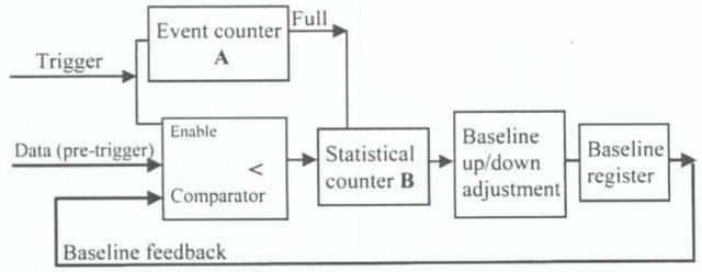
Fig. 5 shows the schematic diagram of this simple FPGA-based SOBLR approach. An event-counter-A counts the number of baseline samples and the baseline-tracking (up/down) adjustment will execute only when the counter-A is full with a good event statistics. When an event-trigger is detected, its pre-trigger data (baseline sample) will be compared to a current baseline reference (a feedback of baseline-tracking register output). And only if the current baseline sample is smaller than the baseline reference, the statistical counter-B will increase by one step, otherwise counter-B holds its previous number. If the baseline reference is identical to the peak as described in baseline histogram, all the total counts located in the left of the baseline-peak is half of the non-pileup events with probability of B/A = 0.5 * P0. Hence, when the event counter-A is full, if the measured B/A ratio is smaller than 0.5 * P0, meaning that, the current baseline reference is smaller than the actual baseline (located in the left to the peak in the baseline histogram), then the reference baseline (baseline register output) needs to be increased by one step; otherwise if the B/A is larger than 0.5 * P0, then the tracking-baseline register output would be decreased by one step. This simple approach consists of two digital counter/timers, one comparator, one register and one subtraction unit, and it can be easily implemented in a FPGA to self-track the baseline without a micro processor involved.
Fig. 5.
A simple FPGA-based SOBLR approach.
III. Results and Discussion
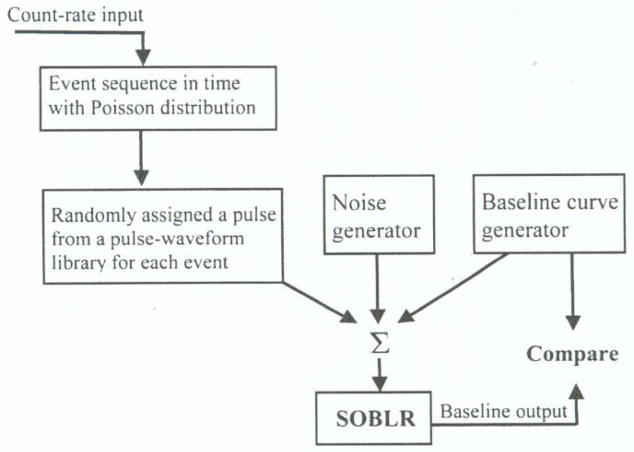
To evaluate this SOBLR method we developed a Labview program with functions as shown in Fig. 6. First we built a pulse waveform library with 10 000 individual pulses recorded by a digital oscilloscope (Tektronix DPO 7104) from a test-bench with one LSO scintillation detector (4 × 4 × 20 mm3) coupled to a photomultiplier tube (Hamamatsu R9779). Based on an input count-rate, we generated an event sequence in time following Poisson distribution indicating the arriving time of events and each event was randomly assigned one waveform read from the library. Hence we generated a sequence of pulses for the certain event-rate including pileups. We also generated Gaussian white noise and a slow drift baseline to mix with the above sequence of pulses. Then the mixed signal went to a simulated SOBLR unit (modeling as the hardware approach). The results of SOBLR baseline outputs were compared to the ideal early-generated baseline curve at different baseline peak-searching methods and as well as the noise levels.
Fig. 6.
A simulation setup for evaluation of this SOBLR method.
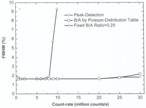
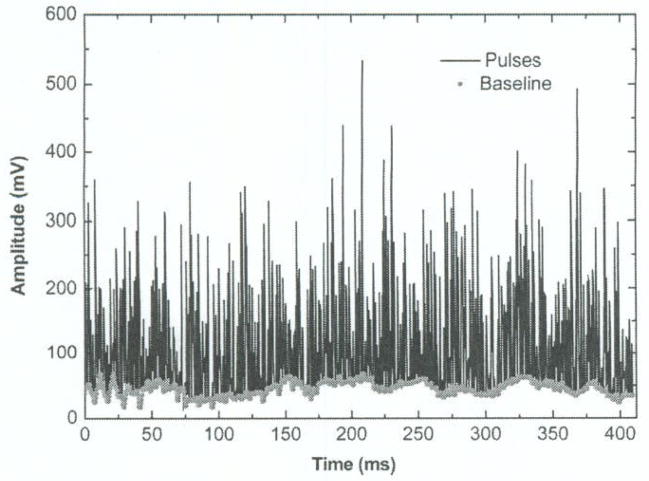
In Fig. 7, we compared three difference baseline peak-tracking methods: a traditional peak-detection, a B/A ratio followed by the non-pileup Poisson-distribution at different count-rates and a fixed B/A ratio of 0.25 for all the rates. The SOBLR using a B/A ratio as a function of count-rate following Poisson distribution has a similar result of using peak-detection for baseline and both show < 2% error up to 30 Mcps. Because the baseline peak is narrow and sharp (Fig. 3), hence the peak tracking is not sensitive to the number of B/A ratio. A simple approach of using a fixed B/A ratio of 0.25 works very well for rates below 8 MCPS, Fig. 8 shows using a fixed B/A ratio of 0.25, the baseline movement is being tracked accurately even at a high count-rate of 5 Mcps.
Fig. 7.
511 keV gamma energy measurement errors caused by this SOBLR with different baseline identification methods.
Fig. 8.
Example of SOBLR self-tracking with a fixed B/A=0.25 at a 5 Mcps event-rate.
In fact, the peak-locating scheme in SOBLR is working as noise filtering; hence the baseline result of SOBLR is less sensitive to background noise than that of a traditional BLR. In a high count-rate and high-noise background as shown in Fig. 9, our simulation found both peak-detection and Poisson distribution table-lookup based B/A for peak-locating worked very well although the baseline peak in the histogram was widely spread (Fig. 10). But for a SOBLR with fixed B/A ratio of 0.25 the baseline-tracking accuracy decreases as the noise level increases.
Fig. 9.
Simulated pulses at 5 Mcps count-rate and high background noise.
Fig. 10.
A histogram of baseline samples at simulated high count-rate and high background noise.
IV. Conclusion
A novel digital statistics-based online baseline restorer has been developed for a digital LYSO PET camera. Each SOBLR can work up to 8 Mcps using a fixed B/A ratio or up to 30 Mcps using Poisson lookup-table of B/A in a simple FPGA implementation, with error < 2% FWHM for 511 keV gamma.
A simple approach of SOBLR with a fixed B/A ratio is implemented by FPGA for our digital PET (currently under development). It has a total of 336 SOBLR channels distributed to 12 Altera’s cyclone-III FPGA (EP3C40F780) to allow a total singles count-rate of 2 600 Mcps (much higher than the 40 Mcps needed in a typical clinical PET). This method is currently coupled to a DC-coupling system only. This simple high-performance SOBLR improves the BLR performance and eliminates the analog BLR ASIC in a digital PET camera and reduces front-end electronics noise and production cost.
In addition to the PET application, this SOBLR method can also be used in other large-scale pulse counting digital systems such as the optical pulse counting system, gamma cameras, spectroscopy and high-energy physics. One limitation of digital baseline restorer without analog feedback is that the input pulse signal mixed with baseline should be within the ADC’s input dynamic range. As for the future work, we need to extend the SOBLR targeted for low count-rate applications with multiple baseline samples per pulse.
Acknowledgments
This work is support in part by the NIH-CA76246 PHS Grant, NIH-EB01481 PHS Grant, NIH-EB00217 PHS Grant, NIH-EB01038 PHS Grant, U.S. Army-Breast Cancer Research Grant.
References
- 1.Fairstein E. Gated baseline restorer with adjustable asymmetry. IEEE Trans Nucl Sci. 1975 Feb;22(1):463–466. [Google Scholar]
- 2.Ohkawa S, Husimi K. Logarithmic converter stabilized by a baseline restorer employing gain switching. IEEE Trans Nucl Sci. 1979 Feb;26(1):433–437. [Google Scholar]
- 3.Kuwata M, Maeda H. New baseline restorer based on feed forward differential compensation. IEEE Trans Nucl Sci. 1994 Aug;41(4):1236–1239. [Google Scholar]
- 4.Geraci A, Rech I, Gatti E, Ripamonti G. Shared baseline restoration at minimum noise for high resolution spectroscopy. Nucl Instrum Methods. 2002 Jul;A 482:441–148. [Google Scholar]
- 5.Abbiati R, Geraci A, Ripamonti G. Self-configuring digital processor for on-line pulse analysis. IEEE Trans Nucl Sci. 2004 Jun;51(3):826–830. [Google Scholar]
- 6.Wen X, Wei Y. Optimum digital filters for baseline restoration. IEEE Trans Nucl Sci. 2006 Dec;53(6):3865–3869. [Google Scholar]
- 7.East LV. Baseline stabilization in direct coupled counting system. Rev Sci Instrum. 1970;41:1245–1246. [Google Scholar]
- 8.De Geronimo G, O’Connor P, Grosholz J. A CMOS baseline holder (BLH) for readout ASIC. IEEE Trans Nucl Sci. 2000 Jun;47(3):818–822. [Google Scholar]
- 9.Swann BK, et al. A custom mixed-signal CMOS integrated circuit for high performance PET tomograph front-end applications. IEEE Trans Nucl Sci. 2003 Aug;50(4):909–914. [Google Scholar]
- 10.Rochelle JM. Fully integrated current-mode CMOS gated baseline restorer circuits. IEEE Trans Nucl Sci. 1995 Aug;42(4):729–735. [Google Scholar]
- 11.Wong WH. A positron camera detector design with cross-coupled scintillators and quadrant sharing photomultipliers. IEEE Trans Nucl Sci. 1993 Aug;40(4):962–996. [Google Scholar]
- 12.Ramirez R, et al. High-resolution L(Y)SO detector using PMT-quadrant-sharing for human and animal PET cameras. IEEE Trans Nucl Sci. 2008 Jun;55(3):862–869. doi: 10.1109/TNS.2008.922832. [DOI] [PMC free article] [PubMed] [Google Scholar]
- 13.Wong WH, Li H, Uribe J, Baghaei H, Wang Y, Yokoyama S. Feasibility of a high speed gamma camera design using the high-yield-pileup-event-recovery (HYPER) method. J Nucl Med. 2001 Apr;42(4):624–632. [PubMed] [Google Scholar]
- 14.Wong WH, Li H, Uribe J. A high count rate position decoding and energy measuring method for nuclear cameras using anger logic detectors. IEEE Trans Nucl Sci. 1998 June;45(2):1122–1127. [Google Scholar]
- 15.Li H, et al. The engineering and initial results of a transformable low-cost high-resolution PET camera. IEEE Trans Nucl Sci. 2007 Oct;54(5):1583–1588. [Google Scholar]
- 16.Fontaine R, et al. The hardware and signal processing architecture of LabPET™, a small animal APD-based digital PET scanner. IEEE Trans Nucl Sci. 2009 Feb;56(1):3–9. [Google Scholar]


