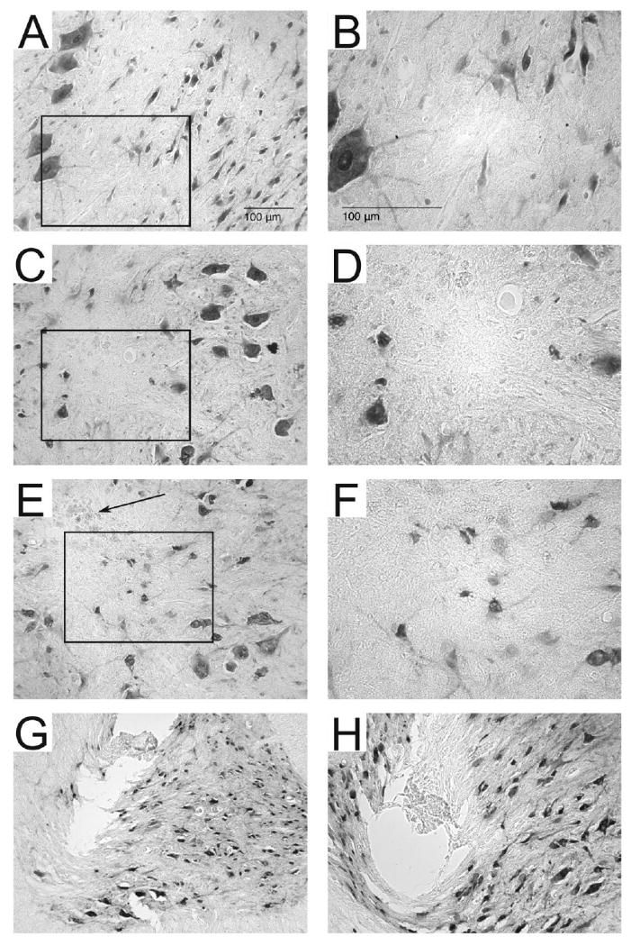
Figure 7. Neuronal density around microwires and in control tissue.

Shown are representative sections immunoreacted with NeuN in spinal control tissue (A, B), around an unpulsed microwire track (C, D) and around a pulsed microwire track (E, F). Boxed outlines in A, C, E indicate the enlarged areas in B, D, F. Panels C and E are representative of the microwire track most commonly observed following explantation and illustrate the difficulty associated with locating microwire tracks on tissue sections stained for NeuN. Darkly stained NeuN+ neurons can be seen surrounding the tracks of both pulsed and unpulsed microwire tracks. The microwire tracks themselves did not contain NeuN+ cells and often displayed bits of the insulation which were stripped from the microwire tip during explantation (arrow in panel E). Explantation of the microwire tips caused tearing of the tissue surrounding the microwire tracks in panels G and H. In panel G the tissue was pulled upwards along with the explanted microwire. In panel H the tissue subjacent to the microwire track can be seen to be compressed by the microwire, likely due to inadequate sharpening of the microwire tip.
