Abstract
Because prostate cancer cells metastasize to bone and exhibit osteoblastic features (osteomimicry), the interrelationships between bone-specific microenvironment and prostate cancer cells at sites of bone metastasis are critical to disease progression. In this work the bone marrow microenvironment in vitro was recreated both by tailoring scaffolds physical properties and by functionalizing electrospun polymer fibers with a bioactive peptide derived from domain IV of perlecan heparan sulfate proteoglycan. Electrospun poly (ε-caprolactone) (PCL) fibers and PCL/gelatin composite scaffolds were modified covalently with perlecan domain IV (PlnDIV) peptide. The expression of tight junction protein (E-cadherin) and focal adhesion kinase (FAK) phosphorylation on tyrosine 397 also were investigated. The described bioactive motif significantly enhanced adherence and infiltration of the metastatic prostate cancer cells on all modified electrospun substrates by day 5 post-seeding. Cells cultured on PlnDIV-modified matrices organized stress fibers and increased proliferation at statistically significant rates. Additional findings suggest that presence of PlnDIV peptide in the matrix reduced expression of tight junction protein and binding to PlnDIV peptide was accompanied by increased focal adhesion kinase (FAK) phosphorylation on tyrosine 397. We conclude that PlnDIV peptide supports key signaling events leading to proliferation, survival, and migration of C4-2B cancer cells; hence its incorporation into electrospun matrix is a key improvement to create a successful three-dimensional (3-D) pharmacokinetic cancer model.
Keywords: polycaprolactone, gelatin, composite, electrospinning, mechanical properties, protein attachment, perlecan, cancer cell adhesion
1. Introduction
Cancer cells reside in an organ-specific host microenvironment that long has been underemphasized as a unique niche for cancer progression. A large number of the published literature suggests that tumor-microenvironment interaction controls cancer growth, invasion and distant metastasis. Tumor associated stroma, the connective, nonfunctional supportive framework surrounding growing cancer cells, actively fuels the progression of prostate cancer. Reactive stromal cells can exert a pro-invasive signal, increasing motility, and decrease apoptosis of cancer cells [1,2].
Studies of prostate, breast and several other cancer types that migrate into bone [2] suggest that bone matrix proteins confer increased cancer cell growth, adhesion, migration and invasion [3-5]. A reciprocal cancer cell-microenvironment interaction facilitates osteomimicry by cancer cells [6], a process by which cancer cells mimic gene expression profiles of cells in their microenvironment. Prostate cancer cells can express bone-like osteomimetic properties; proteins commonly associated with bone cells including osteocalcin, bone sialoprotein, osteopontin, osteonectin, and parathyroid hormone-like related proteins have can be expressed by prostate cancer cells [3, 6, 7, 8]. Hence, a bone-directed targeting strategy would be highly selective and effective against bone metastasis. To achieve this, a more comprehensive understanding of the cross-talk between cancer cells and organ-specific stromal microenvironments is needed [3,6].
The small fiber diameters and interconnected porous network of electrospun polymer fiber mats create ideal conditions for the production of artificial extracellular matrices (ECM) and cell culture applications. In principle, such scaffolds can mimic the structure and morphology of the ECM components in the body, and provide topographical cues to control and enhance tissue regeneration [9, 10]. However, it is critical to reconstruct not only physical and structural characteristics, but also to provide effective biochemical stimuli found in native microenvironment, including various growth factors, hormones, and adhesion molecules [2-7]. Electrospun scaffolds also may be functionalized through the inclusion of drugs and proteins to provide biochemical cues [11–15]. Cells that come into contact with such modified scaffolds respond to the biochemical stimuli through highly specific interactions between cell surface receptors with the fiber immobilized ligands [16].
Poly (ε-caprolactone) (PCL) is a semi-crystalline biodegradable member of the polymer family of poly α-hydroxy aliphatic polyesters. Compared with other polyester family members such as poly(lactide) (PLA), poly-(glycolide) (PGA), and poly(lactide-co-glycolide) (PLGA), PCL has been less frequently used as a material for fabricating biomaterial scaffolds, mainly because of concern over its slower degradation kinetics and adequate cell binding properties. Synthetic and composite 3-D matrices comprised of completely synthetic PCL fibers for culture of fetal bovine chondrocytes (FBCs) were fabricated [17]. Electrospun gelatin and PCL/gelatin composite scaffolds were evaluated for the culture of bone marrow stromal cells (BMSC) [18], and engineering of a three-dimensional (3-D) bone marrow microenvironment for stem cell research has been undertaken [19]. PCL and PCL/gelatin electrospun fibrous mats have not been investigated, however, for their compatibility with cancer cells. The similarity between cancer and stem cell developmental biology and osteomimicry with bone marrow stromal cells suggests that prostate cancer cells are compatible with the described electrospun substrates. We previously produced and characterized 3-D electrospun collagen matrices that structurally, functionally and chemically mimic bone microenvironment with collagen type I as a main component. However, study of the function of any particular motif in a highly biomimetic collagen environment can be problematic because collagen has a large number of cell-binding sites including the well- known RGD peptide sequence [20].
In cancer research there is an increasing need for a physiologically mimetic 3-D tissue culture model to study how structural and biochemical cues provided by the tissue microenvironment modify tumorigenic phenotypes [21]. For example, the role of cancer adhesion molecules (CAMs), found in the extracellular domains of various ECMs, has been investigated [22]. These include, for instance, the junction adhesion molecules (JAMs) in breast cancer invasion/metastasis [23] and VEGF and VEGFR in angiogenesis [24]. Changes in the extracellular domain may “transduce” information via the intracellular molecular skeleton to organelles, such as the nucleus, and by doing so contribute to metastasis [25]. This may modify behavior including cancer cell binding, focal adhesion kinase (FAK) activation (via enhanced cell-matrix interactions), and proliferation. Although some CAM molecules contributing to the cancer progression have been identified, the role of many other ECM components remains unknown. A novel adhesive peptide sequence found in domain IV of perlecan heparan sulfate proteoglycan (PlnDIV) was identified and found to improve cell attachment and spreading in vitro in a variety of cell lines [26,27]. A highly hydrophilic amino acid sequence TWSKVGGHLRPGIVQSG which protrudes outward like a “finger” from the beta-sandwich structure may allow a better access to the active site by cell surface receptors. It is possible that this domain is responsible for homophilic binding of perlecan molecules or other protein-protein interactions [26]. This work investigated the role of this peptide in cancer progression in an engineered bone-like microenvironment comprised of synthetic and composite electrospun fibers. We investigated the utility of electrospun polymer fibers functionalized with PlnDIV peptide for their ability to partially mimic bone marrow ECM to culture human bone metastasis derived C4-2B prostate cancer cells [3]. These synthetic and composite scaffolds were designed to provide not only sufficient mechanical and structural properties, but also configured for the successful coupling of PlnDIV peptide to the electrospun fibers to introduce biochemical stimuli supporting prostate cancer cells growth in 3-D. Because of the potential of electrospun PCL and PCL/gelatin membranes as an artificial bone marrow ECM [17-19], we hypothesized that incorporation of PlnDIV peptide into the electrospun polymeric matrix would provide the appropriate chemical cues creating a more biomimetic environment for cancer cells.
2. Materials and Methods
2.1. Materials
Poly (ε-caprolactone) (PCL) (Scientific Polymer Products, Inc, Ontario, NY) was dissolved in 1,1,1,3,3,3-hexafluoro-2-propanol (HFIP) (Sigma Aldrich, St. Louis, MO) at 10% (w/v) for fabrication of PCL/HFIP membranes, and in chloroform (CHCl3) (Sigma Aldrich) at 12% (w/v) for fabrication of PCL/CHCl3 membranes (hereafter referred to as PCL/HFIP and PCL/CHCl3 respectively). The blends of PCL and gelatin in HFIP and in 2,2,2-trifluoroethanol (TFE) (Fisher Scientific, Pittsburgh, PA) were prepared using gelatin (Kodak, Rochester, NY) that was dissolved in HFIP and TFE respectively at 10% (w/v), and then mixed with 10% (w/v) PCL solutions in HFIP and TFE respectively at 1:1 volume ratio (hereafter referred to as PCL/gelatin/HFIP and PCL/gelatin/TFE). A 70% ethanol solution (Fisher Scientific) was used to sterilize the electrospun mats. Electrospun collagen fibers used for the control experiments [Figs.11, 12] were electrospun from 12% (w/v) solution in HFIP using the same processing parameters as for other membranes (Table 2). Collagen type I (rat tales) was obtained from BD Bioscience, San Jose, California.
Fig.11.
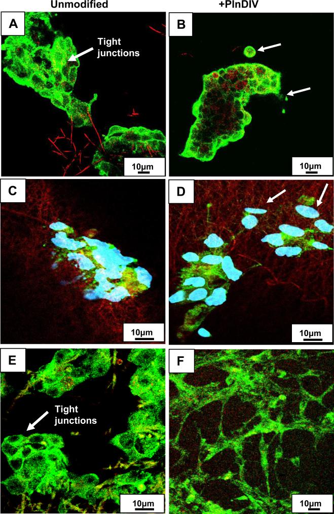
Loss of intercellular adhesion in C4-2B cells grown on PlnDIV modified membrane. Green: staining for E-cadherin (tight junction protein), red: electrospun fibers. PCL/CHCl3 (A). PCL/CHCl3 modified with PlnDIV (B). Nuclei are not shown, scale bar 10 μm. PCL/HFIP(C). PCL/HFIP modified with PlnDIV (D). Blue: staining for nuclei with Draq-5, scale bar 10 μm. Cancer cells are moving away from primary 3-D tumor spheroid (indicated by arrows) as expression of E-cadherin protein was down regulated on PlnDIV modified substrates: (B), (D). Eectrospun collagen/HFIP membrane (E). Collagen/HFIP membrane modified with PlnDIV (F). Scale bars 10 μm.
Fig.12.
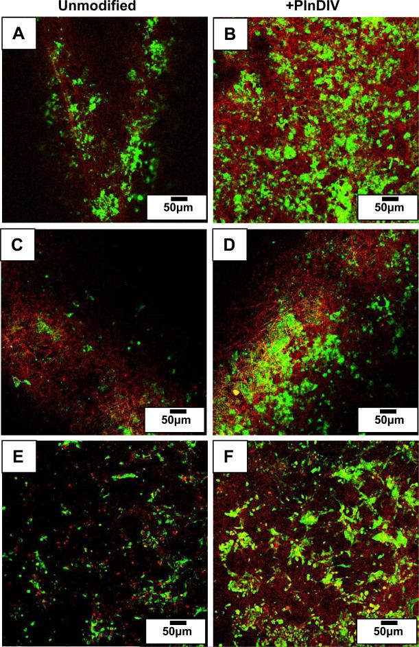
Activation of phospho-FAK in C4-2B cells grown on PlnDIV modified substrates. Green: staining for phospho-FAK, red: electrospun fibers. PCL/CHCl3 (A). PCL/CHCl3 modified with PlnDIV (B). PCL/HFIP(C). PCL/HFIP modified with PlnDIV (D). Electrospun collagen/HFIP membrane (E). Collagen/HFIP membrane modified with PlnDIV (F). Scale bars 50 μm.
Table 2.
Solvent parameters
| Solvent | Boiling Point (°C, 25°C) | Vapor Pressure (Torr, 25°C) | Dielectric constant (ε) | Dipole moment (D) |
|---|---|---|---|---|
| CHCl3 | 61.7 | 158.4 | 4.8 | 1.15 |
| HFIP | 59.15 | 120 | 16.7 | - |
| TFE | 78.2 | 52 | 2.03 | 2.44 |
2.2. Scaffold preparation: electrospinning
Electrospinning parameters including needle gauge, voltage, distance to target, and viscosities of the polymer solutions were optimized to achieve smooth and uniform fibers free of beads. The electrospinning apparatus consisted of a 3 mL syringe (Hamilton, Columbus, OH) connected to a syringe pump (KDS100, KD Scientific Holliston, MA). A high-voltage power supply (Glassman Series EH, Whitehouse Station, NJ) was used to apply a voltage to the tip of a needle. The collector consisted of a 4” × 4” metal sheet covered in non-stick aluminum foil, which was placed 16 cm from the tip of the needle. A needle with 0.51 mm inner diameter (Hamilton, USA), 2 mL/h flow rate, +15 kV applied voltage and 16 cm working distance were employed. Electrospinning processing parameters are listed in Table 2.
2.3. Synthesis of PlnDIV and biotinalation
PlnDIV peptide was synthesized by Lisa Haines-Butterick (Chemistry and Biochemistry, University of Delaware) using solid state peptide synthesis. In order to biotinylate the PlnDIV, 500 μl of 10 mM sulfo-NHS-LC-biotin solution (EZ-Link Sulfo-NHS-LC-Biotinylation Kit, Pierce Biotechnology Inc., Rockford, IL) was added to 500 μl of the PlnDIV water solution (5 mg/ml). The biotin and PlnDIV molecules cross-link via an amide bond. This mixture was placed on ice for 2 h, separated by gel filtration chromatography, and the protein fractions were identified by monitoring at 280 nm. The high molecular weight fractions were pooled and filtered (Amicon Ultra-15, MWCO=5,000 g/mol, Millipore, Burlington, MA).
2.4. Conjugation of PlnDIV-Biotin and BSA
The protocol suggested by the manufacturer was followed for the Imject® Immunogen EDC conjugation Kit (Pierce, Rockford, IL). EDC (10 mg) was added to a 700 μl solution containing 2 mg/ml of PlnDIV-Biotin and 10mg/ml of BSA in conjugation buffer. BSA (molecular weight of 65 kDa) was obtained from Sigma-Aldrich. The reaction mixture was incubated for 2 h at room temperature in the dark. Following incubation, conjugated peptide was separated from unconjugated fraction using gel filtration with D-Salt™ Dextran Desalting Columns (Pierce). Columns were prepared according to manufacturer's protocol. In brief, columns were washed with 15–20 ml of purification buffer followed by addition of 0.5 ml of the Biotin-PlnDIV-BSA mixture that was applied directly to the center of the column disc. The elution of Biotin-PlnDIV-BSA was completed using 8-10 aliquots of 0.5 ml of Purification Buffer. All fractions were collected in separate tubes. Absorbance at 280 nm was measured to locate fractions containing conjugates. The Biotin-PlnDIV-BSA complexes were detected in the first absorbance peak. All fractions with acceptable levels of conjugates were pooled, syringe filtered for sterilization and stored at −20 °C. The highest concentration of the BSA-PlnDIV-Biotin conjugates in the first pooled fraction was determined to be 6.8 mg/mL.
2.5. Hydrolysis of electrospun PCL and PCL/gelatin fibers
The fibers were immersed in 0.5 M sodium hydroxide solution (Sigma Aldrich) for 1 h. After hydrolysis, the fiber surfaces were protonated with 0.01 M HCL (Sigma Aldrich) solution to yield fiber surfaces bearing carboxylic groups.
2.6. Attachment of Biotin-PlnDIV -BSA complexes to electrospun fibers
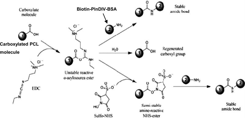
BSA-PlnDIV-Biotin conjugates were attached to the electrospun PCL and PCL/gelatin fibers using a coupling reaction with 1-ethyl-3-(3-dimethylaminopropyl) carbodiimide hydrochloride (EDC, Pierce) and N-hydroxysulfosuccinimide (NHS, Pierce). EDC is a water-soluble carbodiimide used to activate carboxyl groups for reaction with primary amines. An unstable, amine-reactive intermediate (O-acylisourea) is formed by the reaction of EDC with a carboxyl group. This intermediate can react with another amine or can be hydrolyzed. To stabilize this intermediate, NHS was added. NHS converts the amine-reactive O-acylisourea into an amine-reactive NHS ester. This stabilization increases the overall efficiency of the coupling reaction and allows for “two-step” cross-linking to occur where only one carboxyl group on a PCL is coupled, leaving the other free for further coupling chemistry [28]. A schematic of this reaction from the Pierce Biotechnology catalog is shown on Scheme 1. Before coupling Biotin-PlnDIV-BSA conjugates to the electrospun membranes, the fibers were rinsed three times with PBS. PCL/HFIP and PCL/gelatin/HFIP and membranes were placed on the bottom of 8-well chamber slides (Fisher Scientific). MES buffer (1 mL) (50 mM, 2-(N-morpholino)ethanesulfonic acid, (Acros Organics, Fairlawn, NJ), was added to each well with electrospun membranes on the bottom of the well. Membranes then were incubated at room temperature for 1 h. After one hour the MES buffer was removed and 1 ml mixture of EDC (30 mM) and NHS (6 mM) in MES buffer (50 mM) was added to each well. 100 μL of Biotin-PlnDIV-BSA solution was added then to each well. The samples were incubated in this solution for 3 h at room temperature. The fibers then were washed three times with PBS and membranes were ready for UV sterilization followed by cell seeding.
Scheme 1.
Attachment of Biotin-PlnDIV-BSA complexes to carboxylated electrospun membranes (EDC/NHS reaction scheme)
To determine if the EDC/NHS coupling of biotinylated PlnDIV molecules to the fibers was successful, we performed all the steps described above but used 12-well polystyrene assay plates (Corning Inc, Lowell, MA) instead of chamber slides that were used only for imaging purposes. All four PlnDIV functionalized membranes were placed on the bottom of the well of 12-well plate and weighed prior to surface modification. As-spun unmodified membranes also were placed in the same 12-well plate and served as controls. Horseradish peroxidase-conjugated NeutrAvidin (NA-HRP, Pierce, 0.1μg/ml) was used to determine the concentration of the biotinylated species. The experiments were conducted at room temperature; 12-well polystyrene plates were blocked with 3% (w/v) BSA in PBS-T (Invitrogen, Carlsbad, CA) for 24 h, and the electrospun membranes were blocked for 1 h using the same blocking solution. Samples were placed in the wells and incubated with 500 μL of NA-HRP (in SuperBlock buffer) at room temperature for 30 min. The fibers then were washed three times with PBS-T and incubated in 500 μL per well, of 1-StepTM Ultra TMB-ELISA substrate solution (Pierce Biotechnology, Rockford, IL) for 10-12 min. Aliquots (50 μL) of the colored solution were removed and mixed with 50 μL of sulfuric acid (1M) to stop the reaction and allow for optical density measurements. The absorbance, measured at 450 nm, corresponded to the amount of Biotin-PlnDIV-BSA bound to the electrospun fibers. The presence of Biotin-PlnDIV-BSA complex was confirmed by the appearance of a dark blue color on the fibers. The controls for this experiment consisted of PCL and PCL/gelatin electrospun fibers that were exposed to the EDC/NHS reagents but not to the Biotin-PlnDIV-BSA molecules. The data were normalized so that the amount of Biotin-PlnDIV-BSA complex was expressed in mg per one milligram of dry electrospun fibers.
2.6.1. Visualization of bound Biotin-PlnDIV-BSA complexes by confocal microscopy
The presence of Biotin-PlnDIV-BSA complexes on fiber surfaces was confirmed byLaser Scanning Confocal Microscopy (LSCM). The experiments were conducted at room temperature. 8-well Nunc chamber slides (Fisher Scientific) were blocked with 3% (w/v) BSA in PBS-T (Invitrogen) for 24 h, and the electrospun membranes were blocked for 1 h using the same blocking solution. Samples were placed in the wells and incubated with 500 μL of NA-FITC (Pierce Biotechnology) in SuperBlock buffer at room temperature for 30 min. The fibers then were washed three times with PBS-T to prepare for confocal fluorescence microscopy. Image data was obtained on an inverted 100M Axioskop equipped with a Zeiss 510 LSM confocal optics (Carl Zeiss, Oberkochen, Germany).
2.7. Scaffold Characterization
2.7.1. Fiber size and morphology: Field Emission Scanning Microscopy (FESEM)
The diameter and morphology of the electrospun polymer fibers were determined by field emission scanning electron microscopy (JEOL JSM-7400F, Japan). Fibers were directly electrospun onto aluminum foil and attached to SEM mounts using carbon film, and sputter coated with gold for image analysis. The micrographs used for these studies were acquired under the same magnification, electron beam density, and working distance. The SEM images were analyzed with UTHSCSA Image Tool 3.0 (Freeware provided by the University of Texas Health Sciences Center at San Antonio, USA) to determine average fiber diameters. Thirty random fibers per image were used to calculate the mean and standard deviation of fiber diameters. Pore areas also were measured by a subjective approximation of surface pores in the SEM images (average and standard deviation calculated from 30 measurements per image).
2.7.2 Young's modulus: Atomic Force Microscopy (AFM)
The nanoscale mechanical properties of the electrospun membranes were characterized using silicon nitride tips (Veeco Probes, Camarillo, CA) in contact mode and silicon tips (Veeco) in HarmoniX tapping modes, in contact with individual fibers. For the contact mode experiments, the cantilevers (Veeco) were calibrated using the thermal tune method [29]. For these experiments the tip was brought into contact with the surface using a predetermined amount of force i.e. relative trigger, and the deflection of the cantilever was observed. The amount of cantilever deflection was used to determine the elastic properties of the samples, from which, using the modified Hertz model, the elasticity of the membranes was determined [30]. For the HarmoniX experiments the cantilevers (HMX, Veeco) were calibrated against a known standard material to determine the elastic properties of the samples. Elasticity data, obtained directly from DMT Modulus images, were used to quantitatively define the elasticity of the samples. The elasticity is determined by how the tip responds to the surface, and it measures the oscillations of the tip, which change depending on the elastic properties of the material.
2.7.3. Crystallinity: Wide Angle X-ray Diffraction (WAXD)
Crystallinity of the polymeric fibers in the electrospun membranes was evaluated using WAXD. Measurements were carried out with a fixed anode X-ray generator (Rigaku, Geigerflex, 40 kV and 30 mA) with Cu Kα radiation (λ = 0.1542 nm) with 2θ ranging from 15° to 30°.
2.7.4. Thermal properties: Differential Scanning Calorimetry (DSC)
Thermal properties were evaluated under a nitrogen atmosphere using a differential scanning calorimeter (Pyris 6 DSC, Perkin Elmer,Waltham, MA) using 10°C/min heating and cooling rates with a heating temperature range of 10-100°C. The degree of crystallinity (Xc) was assessed using Pyris 6 DSC software by analyzing the melting curves. Xc was calculated as ΔHm/ΔHmo(1). ΔHm is the enthalpy of melting of electrospun PCL fibers, and ΔHmo is the enthalpy of melting of fully crystalline PCL, which is 136 J/g [31].
2.7.5 Molecular structure: Raman Spectroscopy
The Raman measurements were performed on FT-Raman 960 (Thermo Nicolet, USA) using OMNIC software for Raman. The spectra were obtained by accumulating 128 scans in the range 1000–4000 cm-1 with a resolution of 4 cm-1. The crystallinity of electrospun scaffolds was determined using a method considering a characteristic band of the semicrystalline polymer as the superposition of the intensities of crystalline Ic and the amorphous Ia spectral components, and assessing the crystallinity as the fraction of the crystalline phase using the equation: Xc= Ic/Ic+Ia. [32,33]. The peaks at 1736 cm-1 and 1730 cm-1 correspond to the bands assigned to the amorphous phase [32, 33] while the peak at 1720 cm-1 corresponds to the crystalline constituent of the carbonyl vibration region of Raman spectra [32, 36].
2.8. Biological evaluation of C4-2B cells
2.8.1. C4-2B cell culture
C4-2B cells were maintained in T-culture medium supplemented with 5% (v/v) fetal calf serum, and 1% (w/v) penicillin/streptomycin as described previously [74]. The cells were passaged using 1:8 dilution every 5 days. Cell culture media was changed every other day.
2.8.2. Cell seeding and attachment
The C4-2B cells were detached with 1% (w/v) trypsin/EDTA solution at 80-90% confluency level, pelleted by centrifugation and re-suspended. Before cell seeding the electrospun membranes were sterilized with 70% (v/v) ethanol for 30 min, and subjected to UV light for 2 hours. After washing extensively with phosphate buffer saline (PBS) (Sigma Aldrich), electrospun membranes were placed into a Multiscreen Dot Blot apparatus (BIO-RAD Labs, Hercules, CA) for proliferation studies. C4-2B cell suspension (100 μl per well) in T-culture medium supplemented with 5% (v/v) FBS was then added to each well. Electrospun membranes with attached cells were incubated in a humidified atmosphere of 95% air and 5% CO2. Culture medium was changed every other day. For confocal imaging, cell-seeded electrospun membranes were placed on the bottom of 8-well chamber slides (Thermo Fisher Scientific). After 3 days of culture they were washed three times with PBS buffer (Sigma Aldrich), stained with Draq 5 nuclear stain (1:1000 dilution in PBS) (Biostatus, Leicestershire, UK) for 10 min, then washed once with PBS solution, and then were ready for observation.
2.8.3. Adhesion and spreading
An inverted 100M Axioskop equipped with a Zeiss 510 LSM confocal microscope was utilized for laser scanning confocal microscopy (LSCM). Images were obtained in order to assess adhesion properties of C4-2B cells grown on various scaffolds. Electrospun membranes were placed on the bottom of eight-well chamber slides, and cells were seeded at a density of 105cells/well. After three days of culture C4-2B cells were fixed with 4% (w/v) paraformaldehyde for 10 min, and then permeabilized with 0.2% (v/v) Triton X-100 in PBS for 10 min at room temperature. The membranes then were blocked for 45 min with 3% (w/v) BSA. Alexa Fluor® 488 nm phalloidin (Invitrogen) was added to each well at a 1:100 dilution in PBS, and incubated for 40 min at 37°C. After extensive washing in PBS, nuclear stain Draq-5 at a 1:1000 dilution in PBS was added and incubated for 10 min at room temperature. Membranes were rinsed three times with PBS and then visualized by confocal microscopy.
2.8.4. In-growth of C4-2B cells
LSCM Z-axis imaging was used to measure cells in-growth using imaging software suppied with the microscope (LSCM Image Viewer, Carl Zeiss, Oberkochen, Germany).
2.8.5. Immunochemistry
FAK activation
Cells were plated onto coated wells as described above for the cell adhesion assay, then fixed in 4% (v/v) paraformaldehyde for 40 min, then washed twice with 1x PBS. Cells were prepared for FAK staining as suggested by the manufacturer (Upstate Biotechnology, Lake Placid, NY now Millipore, Billerica, MA) except that PBS was used instead of TBS. Cells were permeabilized using 0.1% (v/v) Triton X-100 for 5 min at room temperature, then blocked with 3% (v/v) heat-denatured BSA for 30 min. After wash, cells were incubated in1:75 dilution of rabbit anti-phospho FAK (Y397) for 1 h then washed twice in PBS prior to addition of secondary antibody (anti-rabbit IgG) for 30 min. Detection was performed using Alexa 568 conjugated secondary antibodies against rabbit IgG (Invitrogen). Cells were examined using a fluorescence microscope equipped with a digital camera.
Tight junction's protein (E-cadherin)
Cells were seeded on 8-well Nunc chamber slides (Fisher Scientific) with functionalized PCL/CHCl3 membrane on the bottom of each well. Unmodified membrane served as a positive control. Cells were fixed with paraformaldehyde (Sigma, 4%(v/v)) for 40 min, then washed twice with 1X PBS and permeabilized with 0.1% (v/v) Triton X-100. Cells were blocked overnight in 3% BSA in PBS (w/v). Primary antibody, anti-mouse FITC-conjugated E-cadherin (BD, Pharmingen, San Diego, CA) was applied for 1 hr at 37°C in a humidified chamber. After extensive washing in PBS, nuclei stain Draq-5 (Biostatus) at a 1:1000 dilution in PBS was added and incubated for 10 min at room temperature. Membranes were rinsed three times with PBS and then visualized by LSCM.
2.8.6. Proliferation assay
In order to evaluate growth properties of cells seeded on functionalized substrates, a WST assay from Roche Applied Science (Roche Molecular Biochemicals, Mannheim, Germany) was used to estimate the total number of viable cells on different substrates. This assay is based on the principle that metabolically active cells will react with a water-soluble tetrazolium salt, identified as WST reagent, to produce a soluble formazan dye that absorbs at 450 nm with a reference wavelength of 405 nm. The number of viable cells was estimated by comparing the absorbance value against a standard curve. C4-2B cells were seeded onto the electrospun membranes modified with PlnDIV inside a 96-well dot blot apparatus (BIO-RAD Labs), at a cell density of 5000 cells per well in a serum supplemented culture medium. At each time point the original medium was removed and 100 μl of fresh medium was added to each well. WST reagent then was added (10 μl per well), and plates were incubated for 1h at 37°C, 5% (v/v) CO2. Unmodified membranes in a 96-well plate format served as a control. Subsequently, the entire medium was harvested and transferred into a new 96-well plate for absorbance measurements in a spectrophotometric plate reader (Dynex Technologies, Chantilly, VA). Because of the differences in surface area between the two modified membranes, data were normalized to the absorbance reading of the initial seeding density (4 hours post-seeding).
2.9. Statistical data analysis
All data are expressed as mean ± s.d. Statistical analysis for cell proliferation assay was evaluated by Student's t-test. Differences were considered significant at *p<0.05 and **P<0.1.
3. Results
3.1. Preparation of scaffolds by electrospinning
Four electrospun membranes were produced to determine optimum scaffold characteristics which provide structural and mechanical cues for attachment and growth of prostate cancer cells. The electrospinning parameters used for the fabrication of PCL and PCL/gelatin composite scaffolds were optimized by performing a series of experiments to investigate the effects of solvent, polymer concentration, flow rate, voltage, and distance between the tip of a needle and grounded collector (data not shown). Three milliliters of polymer solution at a total concentration of 10% (w/v) were used to produce PCL/HFIP membrane, and 12 % (w/v) to produce PCL/CHCl3 membrane. The blends of PCL and Gelatin in HFIP and in TFE were prepared using gelatin that was dissolved in HFIP and TFE respectively at 10% (w/v), and then mixed with 10% (w/v) of PCL solutions in HFIP and TFE respectively at 1:1 volume ratio. We found a 1:1 ratio of PCL/gelatin in HFIP solution to be the best choice on the basis of the relatively short time needed for electrospinning and the characteristics of the electrospun fibers produced.
3.2. Scaffold characterization
3.2.1. Fiber size and morphology
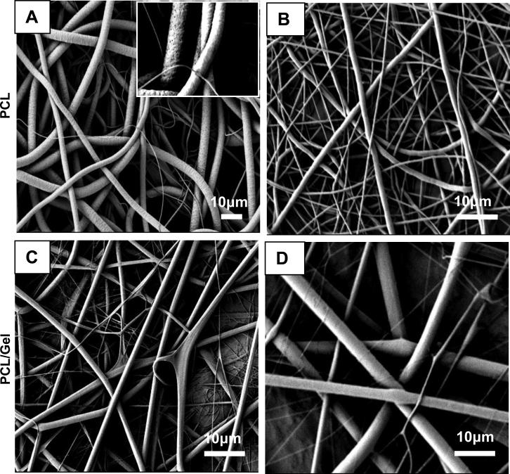
Representative FESEM images showing the microstructure and morphology of the electrospun PCL and PCL/gelatin scaffolds are illustrated in Fig.1. The electrospun PCL fibers produced from chloroform solution (Fig.1A) averaged 3 μm in diameter and had a circular or tube-like appearance with average pore size of 20 μm. In contrast, PCL fibers electrospun from 10% (w/v) solution in HFIP have much smaller average fiber diameter of around 700 nm with a range of 0.5-1 μm (Fig.1B) with an average pore size of 9.4 μm. These fibers had a cylindrical shape and slightly beaded surface morphology without surface pores that can be attributed to a high evaporation rate of this solvent. Average fiber size was 1.5 μm for 10% (w/v) PCL/gelatin fibers produced from HFIP solution with round cross-section and appearance of flat ribbons (Fig.1C). Fiber diameters between 600 nm and 3.7 μm were observed for 10% (w/v) PCL/gelatin/TFE scaffolds accordingly with smooth surface topography and bimodal distribution of fiber diameter (Fig.1D). Table 1 provides a summary of mean fiber diameter and pore size for all electrospun substrates and expressed as mean ± s.d. Average fiber diameters and pore size are reported in the summary table (Table 4), and solvent parameters that can influence fiber size and morphology are listed in Table 2.
Fig.1.
FESEM micrographs of electrospun fibrous membranes. PCL membrane electrosun from 12 %(w/v) solution in chloroform, inset: appearance of pores with ~100 nm in diameter (A). PCL membrane electrosun from 10 %(w/v) solution in HFIP (B). PCL/gelatin membrane electrosun from 10%(w/v) solution in HFIP (C). PCL/gelatin membrane produced from 10%(w/v)solution in TFE (D).
Table 1.
Effect of electorspinning on fiber size and porosity
| Polymer/Solvent System | Concentration (%,w/v) | Voltage (V) | Working distance (cm) | Flow rate (ml/hr) | Fiber size (μm)* | Pore size (μm)* |
|---|---|---|---|---|---|---|
| PCL/CHCl3 | 12 | 15 | 16 | 2 | 2.91±1.45 | 20.06±4.31 |
| PCL/HFIP | 10 | 15 | 16 | 2 | 0.61±0.4 | 9.2 ±1.78 |
| PCL/Gel/HFIP | 10 (1:1) | 15 | 16 | 2 | 1.48±0.39 | 18.77±2.94 |
| PCL/Gel/TFE | 10 (1:1) | 15 | 16 | 2 | 4.00±1.53 | 38.19±8.67 |
Expressed as mean ±s.d.
Table 4.
Summary of structure-property-performance relationships
| Scaffolds | Physical properties | Amount of bound Biotin-PlnDIV-BSA complexes (mg)† | Biological performance | ||||
|---|---|---|---|---|---|---|---|
| Average Fiber/Pore size (μm) | DOC (%) | Young modulus (GPa) | F-actin: stress fiber formation | Proliferation rate (%)* 5days/10days | In-growth* (%) | ||
| PCL/CHCl3 | 2.93/20.76 | 60.2 | 1.2 | 0.17 | No | 10.8** | 96.9 |
| PCL/HFIP | 0.73/9.37 | 36.1 | 1.35 | 0.27 | Yes | 16.9/36.4 | 67.5 |
| PCL/gel/HFIP | 1.52/18.59 | 19.8 | 1.58 | 0.23 | Yes | 37.3/92 | 56.4 |
| PCL/gel/TFE | 3.74/38.79 | 25.4 | 0.59 | 0.13 | No | 8.0** | 36.8 |
Values after background subtraction.
Percentage of increase over unmodified contro.
Data from 5 days proliferation assay
3.2.2. Effect of electrospinning on crystalline and molecular structure of membranes
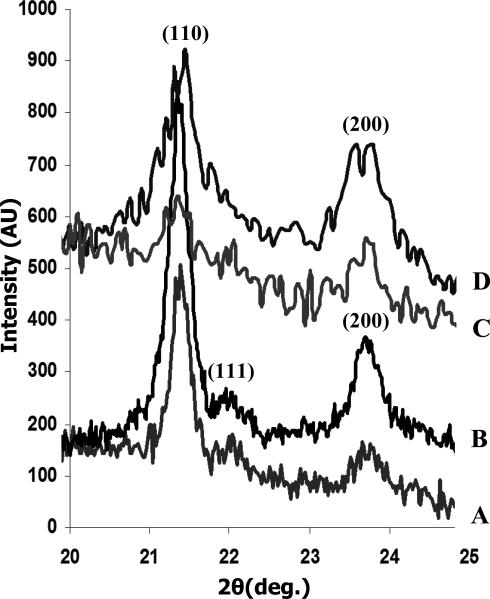
Crystallinity of the polymer in the electrospun meshes was characterized by WAXD, DSC and Raman spectroscopy. The effect of solvent on the development of semi-crystalline structure of PCL and PCL/gelatin scaffolds is illustrated by the WAXD pattern (Fig.2). Differences in crystalline imperfection (i.e. the presence of defects) were evaluated by examining the widths of the scattering peaks for fibers electrospun from different solvents, while the degree of crystallinity (DOC, i.e. volume of crystalline fraction) was calculated from the value of melting enthalpy (ΔHm), which is the integral of the endothermal peak in the DSC curve, using equation (1) from section 2.7.4. WAXD patterns from Fig.2 show two main planes (110, 200), which can be seen in orthorhombic, semi-crystalline PCL [34, 35]. There is a discernable trend in the overall decrease in the crystallinity after addition of gelatin into the PCL solutions. The larger width of the (110) peak (2θ = 21.4°) was observed on fibers electrospun from PCL/gelatin/HFIP and PCL/gelatin/TFE solutions suggesting a decrease in crystalline perfection as compared to PCL/CHCl3 and PCL/HFIP electrospun fibers.
Fig.2.
X-ray diffraction pattern of electrospun substrates: PCL/CHCl3 (A). PCL/HFIP (B). PCL/gelatin/TFE (C). PCL/gelatin/HFIP (D).
A decrease in the intensity of the (111) peak (2θ = 21.9°) relative to that of the (110) peak at 2θ = 21.4° was observed on the fibers electrospun from HFIP solution compared to PCL/CHCl3, and this is indicative of a change in crystallographic texture (i.e. preferred orientation). The intensity ratio of the (111)/(110) peaks for the electrospun PCL/CHCl3 fibers was ~0.13, closer to that for a random polycrystal [35]. For the electrospun PCL/HFIP fibers, the ratio was only ~0.03. This may be also indicative of lower crystallinity in electrospun PCL/HFIP fibers relative to PCL/CHCl3, and it was further investigated by DSC and Raman spectroscopy (Figs.3, 4).
Fig.3.
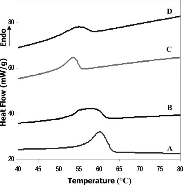
DSC curves of electrospun scaffolds: PCL/CHCl3 (A). PCL/HFIP (B). PCL/gelatin/TFE (C). PCL/gelatin/HFIP (D).
Fig.4.
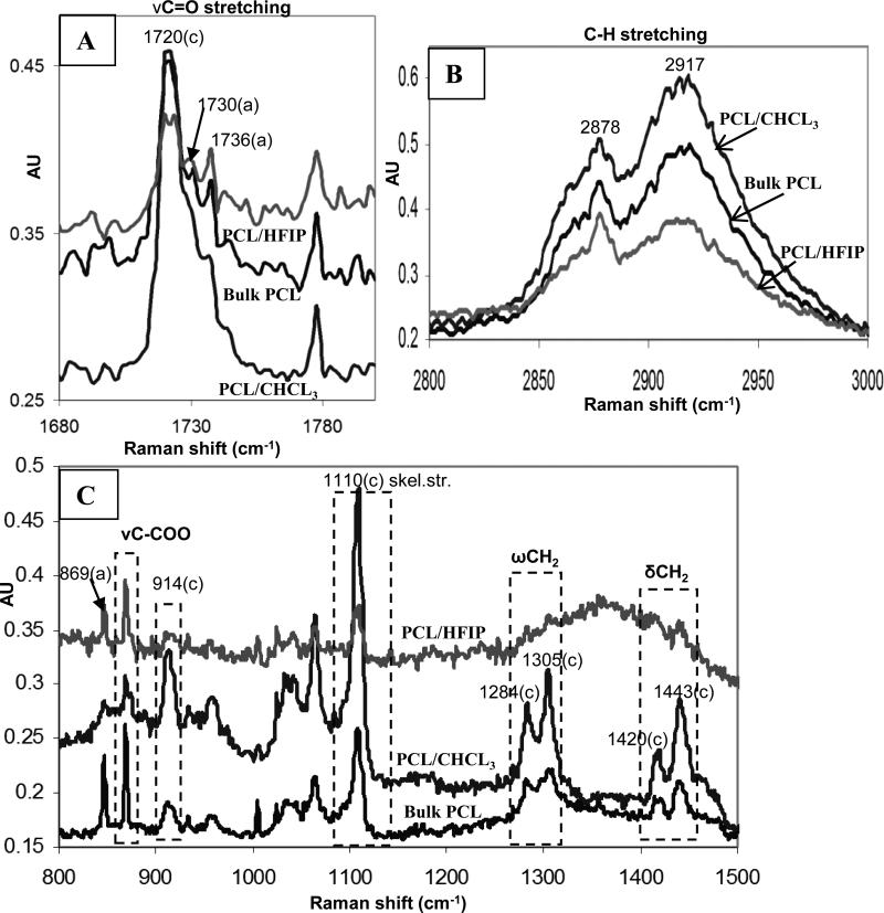
Raman spectra of electrospun PCL membranes. C=O stretching region showing main amorphous and crystalline constituents (A), C-H stretching region exhibiting additional crystalline bands (B), other PCL bands reflecting crystalline domains: 800-1500 cm-1 region (C).
Thermal analysis may be the most routine and simplest method for evaluating crystallinity, but this method also has a disadvantage in that the melting enthalpy of the fully crystalline polymer ΔHmo must be accurately known [33]. DSC results revealed broad melting peaks (Fig.3) that are typical for semi-crystalline polymers [32]. The melting points, Tm, for PCL/CHCl3 and PCL/HFIP are determined to be 60.1°C and 57.6°C, respectively (Table 3). Electrospun fibers varied in their DOC, which is largely influenced by solvent properties and the presence of amorphous polymer (gelatin). The highest crystallinity was found for the electrospun PCL membrane produced from 12% (w/v) solution in chloroform (Xc ~60.2). Addition of the gelatin into the polymer solution resulted in a further decrease in crystallinity and, consequently, a lowered melting point was observed (Fig.3, Table 3).
Table 3.
Crystallinity and thermal properties of electrospun membranes
Additionally, electrospun fibers produced from HFIP solution exhibit even more unusual peak broadening (Fig.3). In order to address potential uncertainties in the crystallinity determination due to unusual peak broadening, we obtained Raman spectra which are sensitive to the degree of crystallinity (Fig.4). Electrospun PCL fibers produced from chloroform and HFIP solutions revealed significant differences in their molecular structure, particularly at 1720-1738 cm-1 assigned to the C=O stretching vibration, 2800-3100 cm-1 for C-H stretching, and also in the 860-1120 cm-1 regions of Raman spectra (Fig 4). The carbonyl region for electrospun PCL fibers and bulk PCL is shown in Fig. 4A. The peaks at 1736 cm-1 and 1730 cm-1 correspond to the band assignment for the amorphous phase, and were the same as reported in the literature [32, 33]. The peak at 1720 cm-1 corresponds to the crystalline component of the carbonyl vibration, and has been found to be very sensitive to the degree of crystallinity [32, 36]. The DOC was calculated using a formula for the intensity ratio of the crystalline and amorphous components as described in section 2.7.5. Results confirmed previous DSC findings that the crystallinity of PCL/CHCl3 electrospun fibers (64.6%) is higher than that of PCL/HFIP (41.8%), and bulk PCL (54.5%). These data are summarized in Table 3.
The CH stretching region (3100–2800 cm-1) is shown in Fig.4B. Two crystalline Raman peaks presenting shoulders were observed at 2917 and 2878 cm-1. The peak intensities from PCL/CHCl3 electrospun fibers were significantly higher compared to PCL/HFIP and bulk PCL. Additionally, the enhanced crystallinity of PCL/CHCl3 fibers relative to PCL/HFIP and control also was confirmed by an increase in peak intensities of other main PCL bands reflecting crystalline domains: 914 cm-1 (νCC of C-COO group), 1443 cm-1 and 1420 cm-1 (δCH2), 1305 and 1284 cm-1 (ωCH2), and at 1110 cm-1 (skeletal stretching) ranges (Fig.4C).
3.2.3. Elastic properties of electrospun fibers
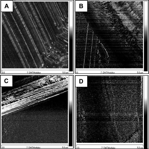
The nanomechanical properties of a single fiber were characterized by force-volume spectroscopy using AFM. Force-displacement curves were generated at 16×16 square grid using the relative trigger mode over a defined area of the fibers. Each force curve was triggered to produce the same maximum cantilever displacement, i.e. the same force was applied to each sample, Young's moduli of the electrospun membranes are listed in Table 4. Generally, the elastic moduli of the electrospun PCL/HFIP (E=1.35GPa) and PCL/gelatin/HFIP (E=1.58GPa) fibers were higher than that of the other two membranes. Fig. 5 shows elasticity profiles of different membranes using the DMT Modulus imaging mode.
Fig.5.
Elasticity profiles of electrospun membranes. DMT modulus images of electrospun PCL and PCL/gelatin fibers: PCL/CHCL3 (A), PCL/HFIP (B), PCL/gelatin/HFIP (C), PCL/gelatin/TFE (D). Scan size 5 μm × 5 μm, scale bar 2GPa. DMT modulus reflects the elasticity of the samples. It is determined by how the tip responds to the surface, and it measures the oscillations of the tip, which change depending on the surface it interacts with.
3.3. Surface modification
3.3.1. Surface hydrolysis of electrospun PCL and PCL/gelatin fibers
PCL does not bear functional groups for direct protein attachment. Thus, to permit a peptide coupling, an ester bond on the PCL backbone was hydrolyzed prior to the cross-linking (coupling) reaction. For this reason, electrospun PCL/HFIP and PCL/gelatin/HFIP fibers were subjected to base-catalyzed hydrolysis. Hydrolysis conditions were optimized for hydrolysis time, temperature and sodium hydroxide concentration. The optimized experimental conditions were found to be 35°C for 1 h at 0.5 M sodium hydroxide concentration. The surface of the electrospun PCL/HFIP and PCL/gelatin/HFIP fibers was activated by alkaline hydrolysis with sodium hydroxide following incubation with HCL that converts hydroxyl groups of the hydrolyzed ester bond into carboxyl groups. The base-catalyzed surface hydrolysis of electrospun PCL/gelatin fibers converts glutamine and asparagine residues on gelatin into glutamic and aspartic acids, respectively, which increases carboxylic acid content.
3.3.2. Covalent modification of hydrolyzed fiber surfaces and quantification of bound Biotin-PlnDIV-BSA conjugates
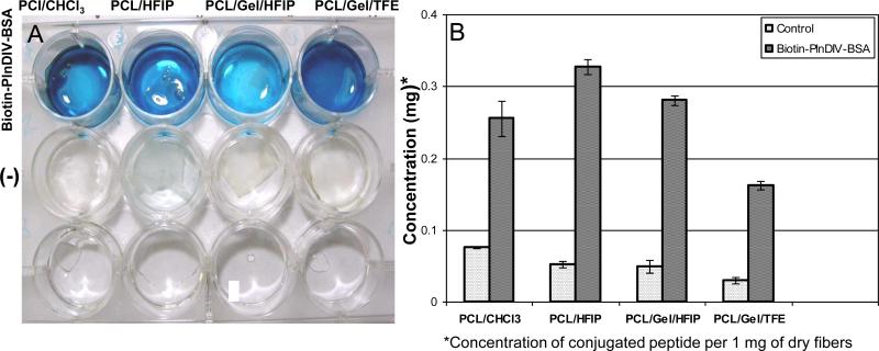
The hydrolyzed surface was modified further by attaching a bioactive motif composed of a Biotin-PlnDIV-BSA complex. The success of the EDC/NHS reaction (Scheme 2) in coupling the Biotin-PlnDIV-BSA complexes to the electrospun fibers was determined by using NA-HRP, which binds to biotin. The blue color indicated the presence of the PlnDIV-Biotin-BSA complex (Fig.6A) on the surface of electrospun fibers. Optical density measurements were performed on PCL/CHCl3, PCL/HFIP, and PCL/gelatin fibers electrospun from HFIP and TFE solutions to determine if there was a difference in the relative amount of Biotin-PlnDIV-BSA complexes bound to the synthetic and composite fibers (Fig.6B). These quantitative measurements revealed a higher conjugate content on the electrospun PCL and PCL/gelatin fibers produced from HFIP solution (Fig.6B). Results are summarized in Table 4 which lists average amount of conjugate attached to various substrates.
Fig.6.
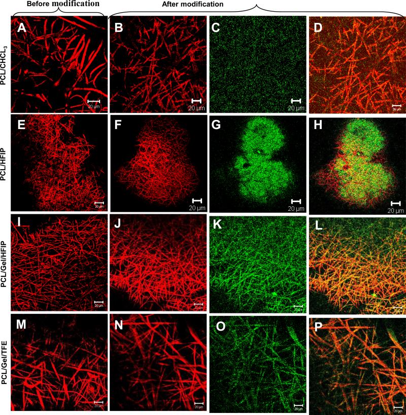
Attachment of Biotin-PlnDIV-BSA complexes to the electrospun fibers. Panel I: A. Digital image confirming presence of bound conjugates on the electrospun fibers. The blue color indicates presence of biotin conjugated complexes remaining associated with the fiber mat on the bottom of the well. B. Amount of bound Biotin-PlnDIV-BSA complexes per 1 mg of dry electrospun fibers. Panel II. Confocal fluorescent images showing distribution of Biotin-PlnDIV-BSA conjugates within electrospun fibers. Red: electrospun fibers (auto-fluorescence and reflectance modes), green: NA-FITC labeled conjugates. (A), (E), (I), (M): confocal images of electrospun fibers before modification (single channel). (B), (F), (J), (N): electrospun fibers after modification. (C), (G), (K), (O): NA-FITC labeled conjugates (single channel). (D), (H), (L), (P): combined images of electrospun fibers and bound conjugates (multiple channels). Scale bar 20 μm. The green fluorescent stain appear” to float” above the fibers because of the nature of the confocal microscope, which is sampling a slice (single focal plane) in the center of the mat and because large diameter fibers are not visible at this focusing distance (located in the different focal plane).
3.3.3. Visualization of bound Biotin-PlnDIV-BSA complexes by confocal microscopy
In order to confirm the presence of Biotin-PlnDIV-BSA complex on fiber surfaces and further investigate if protein coupling can induce changes in scaffold geometry, we obtained confocal fluorescent images. Conjugates were visualized by labeling them with NA-FITC resulting in green appearance of bound Biotin-PlnDIV-BSA complexes. Fig.6 Panel II illustrates that distribution of Biotin-PlnDIV-BSA complex within electrospun fibers was not uniform, with greater coverage for the membranes with smaller fibers diameters (Panel II G, K). Presence of conjugates was observed throughout the entire scaffold depth (z-stack images are not shown). Additionally, fluorescent labeling allowed accessing post-coupling membrane geometry. Imaging revealed that surface modification did not have significant impact on the geometry of modified membranes. A small increase in the diameter of the hydrated composite fibers also was accompanied by slight enlargement of average pore size that is beneficial for tissue culture application.
3.4. Preliminary biological evaluation
3.4.1. Cell adhesion and morphology
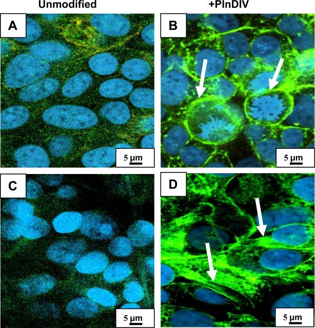
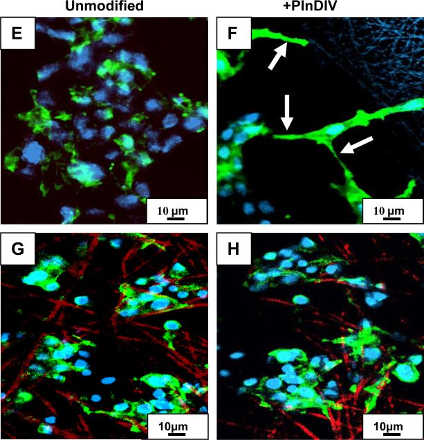
We used confocal microscopy to detect morphological evidence of cell spreading. In addition, staining with fluorescently labeled phalloidin was employed to detect formation and organization of filamentous actin in C4-2B cells grown on electrospun matrices modified with PlnDIV peptide. As shown in Fig.7, intense phalloidin staining on the periphery of the cell membrane representing a well-defined cortical actin, was observed on all PlnDIV modified scaffolds, but not on the unmodified ones (Fig.7B,D,F,H). This is indicative of cells that spread after attaching to the matrices. Significant morphological differences were observed in cells grown on various substrates. C4-2B cells grown on PCL/CHCl3 modified fibers exhibited a round 3-D morphology with less cell body spreading. Subcortical actin was localized at sites of cell-cell junctions beneath the plasma membrane (periphery of the cells). Small, short actin filament complexes were randomly dispersed throughout the cytoplasm of the spherical cells and no large stress fibers were evident (Fig.7B). In contrast, significant differences in cell shape and cytoskeletal organization were seen between cells seeded on PCL/HFIP (Fig.7D) and PCL/gelatin/HFIP (Fig.7F) modified scaffolds. Cells grown on these scaffolds had a more flattened morphology, containing long actin bundles (stress fibers) localized at the protruding cell periphery or extending throughout the entire cytoplasm (Fig.7D, F). Additionally, cells grown on PCL/gelatin/HFIP modified membrane exhibited more elongated spindle-like morphology typical of fibroblasts (Fig.7F). Interestingly, no significant morphological changes were observed on another composite membrane, PCL/gelatin/TFE modified with PlnDIV, although phalloidin staining on the periphery of the cells was more intense than on its unmodified counterpart (Fig.7G,H).
Fig.7.
Cytoskeletal reorganization of C4-2B cells grown on PlnDIV-modified membranes. Panel I: PCL/CHCl3 (A). PCL/CHCl3 modified with PlnDIV (B). PCL/HFIP(C). PCL/HFIP modified with PlnDIV (D). Scale bar 5 μm. Panel II: PCL/gelatin/HFIP (E). PCL/gelatin/HFIP modified with PlnDIV (F). PCL/gelatin/TFE (G). PCL/gelatin/TFE membrane modified with PlnDIV (H). Arrows indicate formation of cortical actin (B) and stress fibers (D, F). Scale bar 10 μm. Note that formation of stress fibers was observed only on PnDIV-modified PCL/HFIP and PCL/gelatin/HFIP membranes.
3.4.2. Cell in-growth
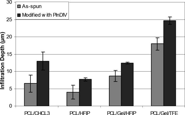
LSCM Z-stacks images revealed that cells attached and infiltrated all the electrospun membranes 5 days post-seeding (Z-stacks images are not shown). Presence of PlnDIV peptide in the electrospun matrices further improved cellular infiltration in these scaffolds (Fig.8). Cells migrated farther away from the surface on all peptide-functionalized membranes with the highest increase on PCL/CHCl3 (~97%, Table 4). Fig.8 demonstrates results of Z-stack imaging analysis where penetration depth of three different areas on each membrane was analyzed in order to produce quantitative results. C4-2B cells formed 3-D spheroids and moved through the spaces between fibers on both modified and naked, as spun, scaffolds that served as positive controls. Significant differences in the infiltration depths between naked and PlnDIV modified scaffolds were observed. Cells migrated farther away from the surface on all electrospun membranes modified with PlnDIV (Fig.8). A quantitative summary of this study is shown in Table 4; all modified membranes exhibited an increase in penetration depth with the largest increase (~97 %) on PCL/CHCl3 modified membrane.
Fig.8.
Ingrowth of C4-2B cells inside naked and PlnDIV modified membranes.
3.4.3. Proliferation assay
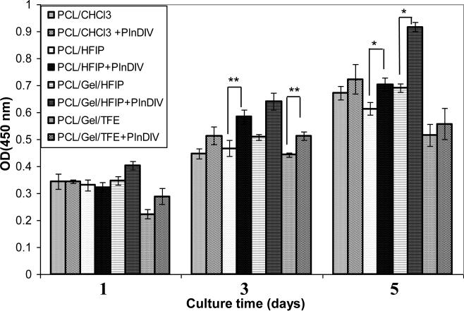
WST assay was performed to evaluate growth properties of C4-2B cells on functionalized scaffolds versus an unmodified control. Originally all four electrospun membranes were tested over 5 days (Fig.9). An increase was seen in proliferation rate on all modified scaffolds over unmodified controls on days 3 and 5 post-seeding with significance level of **P<0.1 for PCL/HFIP and PCL/gelatin/TFE (day 3), and *p<0.05 on PCL/HFIP and PCL/gelatin/HFIP (day 5) electrospun membranes. Because the significance level was higher for the last two scaffolds, we selected them for further testing over a more extended time period.
Fig.9.
Proliferation assay, 5 days time course, *p<0.05, **p<0.1.
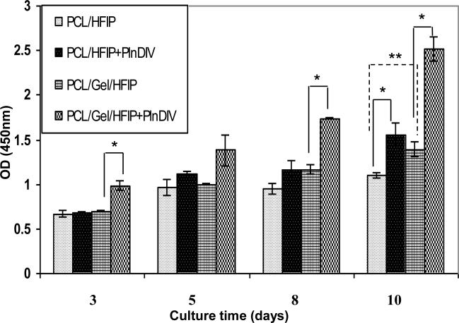
A second proliferation assay was performed on two selected membranes over a 10 day time period: synthetic, PCL/HFIP and composite, PCL/gelatin/HFIP (Fig.10). Both membranes were produced using the same solvent; but they were different in chemical composition, geometry, and effective mechanical properties (see Table 1 and Table 3 for comparison). Cells remained alive and proliferated on both modified scaffolds undergoing approximately a doubling on the PCL/gelatin/HFIP modified membrane, and 1.4 times increase over unmodified control on PCL/HFIP, indicating that the adhesive peptide sequence was responsible for it. However, the two electrospun membranes demonstrated different growth patterns: almost linear growth on PCL/gelatin/HFIP modified membrane versus a plateau in growth between days 3 and 8 on synthetic PCL/HFIP modified membrane.
Fig.10.
Differences in proliferation rate of C4-2B cells grown on PlnDIV modified and naked PCL/HFIP and PCL/gelatin/HFIP membranes, 10-day time course, *p<0.05, **p<0.1.
Therefore, we also evaluated differences in the cell growth rate between unmodified synthetic and composite scaffolds (Fig.10). A considerable increase in growth rate was observed on the naked composite membrane, with significance level of **p<0.05, indicating that PCL/gelatin/HFIP scaffold is more conducive to cell adhesion and proliferation. The cell growth pattern observed on the naked membranes replicates a pattern described above: linear growth on PCL/gelatin/HFIP membrane versus a plateau on days 3-8 on synthetic PCL/HFIP membrane.
3.4.4. Cell-cell and cell-matrix interactions
Two synthetic membranes were used to evaluate cell-cell and cell-matrix interactions. To determine if synthetic scaffolds could alter cellular responses, we used electrospun collagen fibers as a control for this biological evaluation because collagen type I is native to bone marrow ECM. Prostate cancer cells cultured on electrospun scaffolds were analyzed for the presence of tight junction components with and without presence of PlnDIV peptide. Results revealed that for C4-2B cells grown on PlnDIV modified substrates (Fig.11B, D, F), production of E-cadherin at the tight junctions was reduced or lost. Formation of tight junctions was totally lost in cells growing on electrospun collagen membrane modified with PlnDIV (Fig.11F). This cell culture mostly consisted of proliferating cells, suggesting that a native collagen microenvironment actually enhances metastatic potential of PlnDIV peptide. Fig.12 illustrates that binding of C4-2B cells to modified substrates also was accompanied by an increase in FAK phosphorylation on tyrosine 397.
4. Discussion
4.1. Scientific rationale and design principles
The objective of this research was to develop a scaffolding system that incorporates a specific cell recognition motif for prostate cancer cell studies. To this end, we accomplished: 1) tailoring of physical and structural properties of electrospun membranes by tuning their processing parameters for improved biocompatibility, and 2) optimization of a coupling protocol to assure an efficient binding of PlnDIV peptide to electrospun fibers. Finally, we investigated the role of PlnDIV peptide in cancer progression in an artificial bone marrow environment comprised of electrospun PCL and PCL/gelatin fibers.
Poorly-adherent metastatic prostate cancer cells [3] were seeded in four electrospun polymeric membranes mimicking bone marrow ECM. Two were completely synthetic and two were composite membranes that combined PCL with gelatin to overcome limitations seen with scaffolds constructed with either one alone. Initial cell studies with synthetic membranes only showed significant limitations. Such limitations, along with the advantages of incorporating a natural polymer into the engineered scaffolds, are summarized: 1) synthetic PCL membranes suffer from undesirable hydrophobicity. Incorporation of gelatin increases hydophilicity and water uptake [37, 38]. 2) Electrospun PCL/gelatin membranes exhibited improved optical properties due to their transparency in the culture media allowing visualization of the cells using light, fluorescence and confocal microscopy. 3) Electrospun PCL fibers require additional surface modification due to lack of functional groups. Incorporation of gelatin into the scaffold material allows direct surface modification; more binding sites are available for PlnDIV coupling. 4) Due to increased viscoelastisity, composite scaffolds are more pliable that is essential for their cytocompatibility. 5) PCL/gelatin composite scaffolds do not require chemical crosslinking, in contrast to gelatin scaffolds. Hence, addition of PCL to the polymer mixture reduces the potential cytotoxicity of a crosslinking reagent such as glutaraldehyde. 6) PCL/gelatin scaffolds exhibit minimal swelling or contraction as a function of ionic strength changes within the physiological range as compared to gelatin alone. This greatly reduces cell loss, which is a major drawback of tissue culture of poorly adherent cancer cells. 7) As previously shown, PCL scaffolds are hydrolysis-resistant for culture periods over 40 days [39] and can be used for the extended cell studies.
4.2. Physical properties critical for adhesion and growth of prostate cancer cells
Because fiber diameter and surface morphology affect cell attachment, proliferation, migration and cytoskeletal organization, conditions should be optimized for each particular application and cell type [40–42]. Electrospun engineered scaffolds were designed to mimic ECM of bone marrow both structurally, in terms of its 3-D fibrous architecture, and with respect to their mechanical properties. Results were used to optimize scaffold porosity and mechanical compliance for improved biocompatibility.
4.2.1. Fiber diameter and morphology
Cell adhesion, mechanical, optical and transport properties of the electrospun substrates are guided to some extent by their microstructural characteristics. A multitude of electrospinning process parameters and environmental variables impact scaffold geometry and fiber morphology. Such parameters include solvent type, polymer concentration, viscosity, distance of the collecting target from the tip of a needle and applied voltage [43]. Therefore, the effect of solvents and their mixtures on resulting fiber size and morphology was investigated [42]. Solvents for this study were selected based on their ability to alter evaporation rate, thus influencing crystallization kinetics during fiber formation. Electrospun PCL and PCL/gelatin fibers produced from HFIP have a smaller fiber diameter with more uniform fiber size distribution, suggesting that physical characteristics of the solvent can account for this observation (Fig.1B,C). Indeed, the elongation of the jet during whipping instability is higher for HFIP than that for TFE and chloroform due its high polarity (ε=16.7), thereby forming more uniform and smaller fibers [39]. In contrast, increased jet stability during electrospinning from chloroform and TFE minimizes jet thinning, producing larger diameter fibers. Altogether, the control of fiber diameter during electrospinning is a complicated process involving multiple interdependent variables [39].
Interesting morphological features were observed on the surface of the electrospun PCL fibers produced from chloroform such as appearance of pores with ~100 nm in diameter (Fig.1A, inset). We attribute this to a phase separation that occurs during electrospinning in a high humidity environment, such that the water droplets from the air form “imprints” upon solvent evaporation. The effect of environmental humidity on pore formation was studied extensively by our group [44].
Porosity of the electrospun scaffolds greatly affects permeability and transport properties, and it is a critical design parameter. Spacing between fibers is a function of the jet instability, jet velocity, and humidity, among other factors [45]. We found that the pore sizes in all electrospun membranes averaged greater than 10 μm in the hydrated state, both pre- and post-coupling (Fig.6, Panel II). Porosity of all electrospun substrates was not increased significantly after immersion in the culture media. For composite scaffolds, the amorphous regions on gelatin are more likely to be selectively attacked by water molecules, which act like plasticizers, making these membranes more flexible [38]. Therefore, an additional pore enlargement could be expected in vitro, as PCL and PCL/gelatin scaffolds degrade, which should allow improved nutrient and gas exchange and further cellular infiltration [37]. Thus, by using solvents with different polarities and BP, and by optimizing polymer concentrations, we altered the resulting fiber diameters between ~ 600 nm for PCL/HFIP and ~3 μm for PCL/CHCl3, and for composite membranes between 1.4 μm for PCL/gelatin/HFIP and 4 μm for PCL/gelatin/TFE with a pore size greater than 10 μm (except for PCL/HFIP).
4.2.2. Crystalline and molecular structures of electrospun membranes
The substrate to which cells adhere must withstand and resist the tensile forces exerted by cells [46]. Depending on the mechanical properties of the engineered ECM, it can counteract these tensile forces to different extents. This balancing force from the artificial ECM along with intracellular tensile forces determines the cell shape and ultimately associated cellular functions such as proliferation, differentiation, motility, apoptosis, and gene expression [46].
Mechanical compliance and the scaffold's structural integrity are important design considerations for the development of 3-D pharmacokinetic cancer model. Semi-crystalline polymers like PCL consist of soft (amorphous) and hard (crystalline) phases. The soft phase provides the elastomeric characteristics whereas the crystalline phase imparts dimensional stability to the molecular array. The random or ordered arrangements of the amorphous and crystalline phases along with DOC are strongly influenced by the electrospinning process parameters and partially define the mechanical properties of the product [47].
In this work we investigated the effect of solvent and presence of amorphous polymer (gelatin) on the crystallinity and molecular structure of the produced scaffolds. As previously reported, solvent physical characteristics and polymer concentration affect the rate of solidification and crystallization of polymer chains during electrospinning [47]. In this regard, crystallization kinetics may affect the DOC of the electrospun fibers and the resultant mechanical properties. The azimuthal distribution of the two main crystalline reflections (110) and (200) in the electrospun fibers (Fig.2) is nearly isotropic and resembles the randomly oriented PCL polycrystal [34, 35]. However, the intensity ratio I110/I200 of two crystalline reflections is slightly lower for PCL/CHCl3 than for PCL/HFIP. Such an effect can be seen during uniaxial tensile deformation of the orthorhombic semi-crystalline polymer [35]. Polymer chains can be subjected to such deformation during jet instability when electrospun from a highly polar solvent such as HFIP (ε=16.7). Additionally, high solvent evaporation rate retards the crystallization process and lowers DOC for the electrospun fibers due to rapid solidification of the stretched PCL chains (Table 3). According to Zong et al. [48], the stretched chains do not have enough time to organize into ordered lamellae-like structures before they solidify during electrospinning. In contrast, slower crystallization kinetics using chloroform allows more ordered crystalline structures to be obtained.
Interestingly, an increase in the (111)/(110) relative intensity ratio of the (111) peak at 2θ = 21.9° for the electrospun PCL/CHCl3 may be indicative of a difference in crystallographic texture and an increase in crystalline perfection in the electrospun PCL/CHCl3 fibers. We attribute this to slower crystallization kinetics and increased jet stability during electrospinning from chloroform. This finding was confirmed by DSC, which showed an increase in Tm and DOC for PCL/CHCl3 fibers (Table 3). Introduction of gelatin into the polymer mix further reduced the crystallinity that was confirmed by the WAXD pattern and also by analysis of the DSC melting curves.
Significant DSC peak broadening, observed for both synthetic and composite fibers produced from HFIP solutions, may be due to presence of fluorinated groups (solvent inclusion) as was observed earlier [49]. Therefore, we attribute this unusual broadening, more typical for amorphous polymers, to the retardation of crystallization process during electrospinning from HFIP. To address this issue and confirm the crystallinity values obtained by DSC, we used Raman spectroscopy that is suitable for evaluating the extent of conformational isomerism from band assignments, and the degree and nature of crystalline and non-crystalline order from the intensities of the assigned bands [32, 36].
The intensity ratio calculated from the Eq.2 (section 2.7.5) was used to determine the DOC of both electrospun substrates and bulk PCL that served as control (Fig.4A). Results of Raman analysis are listed in Table 3, and agree with other published results [50-52]. For instance, the crystallinity of the cast PCL films measured by FTIR spectroscopy was 49.2%. The crystallinity of the PCL sample used in the same study determined by DSC was ~ 50.2% [33]. The crystallinity of PCL has been reported by others to be 42% by small angle X-ray scattering [50] and NMR [51], and 60% by the density method [52]. This suggests that the crystallinity of electrospun PCL fibers determined in this study by Raman spectroscopy is comparable with values determined by other conventional techniques. Moreover, data obtained by this method agree with DOC values obtained from thermal analysis (Table 3).
4.2.3. Mechanical properties of electrospun substrates
While the mechanical properties of electrospun scaffolds have been measured, the characterization at the single fiber level has been carried out only recently [53-55]. The advantage of such characterization is that it gives the closest estimate of what cells experience in their immediate microenvironment. Cells, when cultured on substrates with appropriate mechanical properties, may display enhanced cellular functions [56, 57].
The observations made by Tan et al. [58] suggest that the elastic modulus for a single fiber increases as the fiber diameter decreases into the nanometer range. Arinstein et al. argued that the orientation of the macromolecules is present in the supramolecular structures of the amorphous phase and plays a dominant role in the abrupt increase of mechanical properties of fibers when the diameter is comparable to the critical threshold scale (~700 nm) [59]. Our results agree with these findings. The elastic modulus of electrospun PCL/CHCl3 fibers (~3 μm in diameter) was lower than that of electrospun PCL/HFIP fibers (~600 nm in diameter), in spite of the higher DOC and melting temperature (Table 3). We suggest that the interplay of two variables such as fiber diameter and DOC determines mechanical properties of the resulting fibers. Indeed, PCL/HFIP fibers, with a diameter similar to the critical threshold value and with a higher content of the amorphous phase demonstrated a higher elastic modulus compared to electrospun PCL/CHCl3 fibers (Table 4).
Therefore, PCL/HFIP and PCL/gelatin/HFIP electrospun fibers with smaller diameter though lower crystallinity exhibited higher elasticity values, at least twice as high as that of bulk PCL. However, as fiber diameter increases, the properties of the single fiber approach that of the bulk. The trend of mechanical enhancement with decreased size also may be observed by comparing the mechanical properties of electrospun PCL fibers (Table 4) with PCL sheets [60, 61].
Hence, gelatin addition increased elasticity for PCL/gelatin/HFIP fibers with diameters within 500nm-1.5μm range that is comparable to the reported threshold value [59]. These findings corroborate other published results. For instance, incorporation of collagen into nanofibers improved fiber elasticity and tensile strength, and increased cell adhesion [62, 63]. In another case, addition of 50% gelatin to PCL improved both the fiber mechanical strength and surface wettability, enhancing cell attachment and growth [37]. The enhanced mechanical behavior of the composite membrane can be attributed to a significant amount of protein within the polymeric fiber acting as cross-linking molecules between crystalline domains (Fig.5C).
The effect of gelatin addition on the elasticity of the PCL/gelatin/TFE system, however, is less conclusive due to a significantly larger fiber diameter. With an increase in fiber diameter the elasticity approaches bulk values observed in PCL sheets [60, 61]. Increased fiber diameter improves plasticity of this membrane (visual observation), but reduces strength and stiffness of the electrospun fibers [37, 64].
4.3. Attachment of PlnDIV peptide to the electrospun fibers
Many tissue engineering studies focus on recapitulating structural and mechanical aspects of the ECM lacking biological elements [65]. Incorporation of these elements allows the engineered scaffold to mimic the ECM both in structure and function. The role of biochemical stimuli has been studied [65], and it found to have a more dominant effect than scaffold's physical characteristics. Recently, Chew et al. [66] mixed human nerve growth factor (NGF) into a copolymer solution of poly-(ε-caprolactone) and poly(ethylethylene phosphate) (PCLEEP) to produce electrospun fibers containing NGF. The growth factor was present in aggregate form throughout the fiber matrix at low loading levels (0.01-0.04%) that can be attributed to the phase separation during electrospinning. This may be due to the different charge densities of the aqueous growth factor solution and the polymer solution. The NGF showed a burst release of 20%, then a steady release over a period of three months. The authors suggested that the electrospinning may have denatured the NGF; however, they could not quantify the NGF bioactivity after release.
An alternative approach, eliminating the denaturing effect of electrospinning, is to covalently couple a bioactive peptide to the electrospun fibers during post-spinning process. A non-woven fabric made up of electrospun polyamide nanofibers supported axonal regeneration in injured rat spinal cord. It was shown that covalent modification of the nanofibers with a bioactive peptide, tenascin-C, derived from the neuro-regulatory ECM enhanced the ability of the nanofibers to facilitate axonal growth [67].
Our current study shows that electrospun PCL and PCL/gelatin fibers can be successfully functionalized with PlnDIV peptide to achieve a high loading level (Table 4). By covalently attaching a novel adhesive peptide to the electrospun PCL and PCL/gelatin fibers, we circumvented some of the problems that Chew and co-workers [66] encountered. To improve binding efficiency and to examine the functionality of PlnDIV peptide in a multivalent configuration, we covalently conjugated this peptide to BSA using a commercial assay [28]. The number of peptides conjugated to BSA in such a preparation ranges from 1 to 14 with a median of approximately seven peptides per BSA molecule [26]. Such presentation increases ligand density and thus improves both adhesion strength and cell signaling, owed to better receptor clustering as needed for formation of focal adhesions [68]. Additionally, using N-hydroxysulfosuccinimide (NHS) as a heterobifunctional linker for the coupling reaction provides greater steric freedom and thus greater specific activity for immobilized biomolecules, especially in the case of smaller peptides [69]. Electrospun PCL/HFIP membrane had the highest conjugate content, because its nanoscale architecture provides higher surface area available for peptide binding [65, 70].
4.4. Preliminary biological evaluation
4.4.1. Cell adhesion and morphology
Cell attachment assays are routinely used in various cell studies, though they do not discriminate between simple binding and binding followed by spreading. Spreading is energy dependent and involves interactions with cell surface receptors, activation of signal transduction cascades and cytoskeletal reorganization [26, 71]. Changes in the cytoskeletal organization affect cell responses and are influenced strongly by the substrate chemical composition and morphology [46]. Consistent with these findings Idowu et al. [72] observed a buildup of large, organized actin stress fibers within the cytoplasm of the flat cells cultured on TCP, but not in the spindle-shaped and round cells of the PCL scaffold. The formation of actin stress fibers can also modulate cellular phenotype. Mallein-Gerin et al. [73] suggested that the chondrogenic phenotype in vitro is modulated by actin organization rather than changes in cell shape.
In this regard, the formation of stress fibers observed on PCL/HFIP and PCL/gelatin/HFIP functionalized membranes (Fig.7D,F) has an important implications. First, it may be indicative of the increased migratory potential, and second, the ability of cancer cell to invade an artificial scaffold, which is a phenotypic feature of C4-2B cells [21]. Interestingly, in our recently published work, we did not observe formation of stress fibers on electrospun collagen membranes and collagen-coated TCP, though collagen is native to the bone marrow ECM [74]. Hence, we conclude that formation of stress fibers can be attributed to the presence of PlnDIV peptide in electrospun scaffolds.
4.4.2. In-growth and migratory potential of C4-2B cells
Cell ingrowth is a desired outcome for most scaffold-based applications [75]. For metastatic prostate cancer cells, penetration depth inside the artificial scaffolds is an important metric of cell-scaffold integration, and it also serves as an index of the migratory potential of the cells. Although all electrospun PCL-based scaffolds showed good compatibility with C4-2B cells, increased cell infiltration inside artificial scaffolds was observed on the membranes with larger pore size and fiber diameter (Fig.8). We suggest that the more spacious coarse membrane's geometry is responsible; engineered materials with a pore size greater than 10 μm encourage tissue ingrowth [37, 74]. Lower infiltration depth was observed on the PCL/HFIP electrospun membrane with pore size less than 10 μm. Biofunctionalized scaffolds further improved cellular infiltration; however, variations in matrix porosity can be a modifying factor.
4.4.3. PlnDIV's role in proliferation of C4-2B cells
Enhanced proliferation was seen on the composite PCL/gelatin/HFIP naked membrane compared to a completely synthetic membrane with **P<0.1. This finding agrees with published results [76] that showed a significant growth improvement of smooth, endothelial, and bone-marrow stromal cells on composite membranes. Interestingly, the increase in proliferation rate observed on functionalized PCL/HFIP and PCL/gelatin/HFIP membranes correlates well with morphological evidences of cancer progression, such as stress fiber formation with fibroblast-like morphology, and also with their higher peptide content and effective mechanical properties.
We conclude that the significant growth advantage is due to the presence of a bioactive peptide favoring matrix adhesion. Matrix-induced growth and survival benefits under poor growth conditions were observed earlier in some tumorigenic and metastatic cell lines including C4-2B [21,77,78].
4.4.4. Cell-cell and cell-matrix interactions
Multiple and diverse cell adhesion molecules direct intercellular (cell-cell) and cell-ECM interactions during cancer progression and metastasis [22]. Recent studies demonstrated the importance of E-cadherin in contact growth inhibition of normal epithelial cells [22]. Many tumor cells maintain strong intercellular adhesion, and are growth-inhibited by cell-cell contact [79]. The rate of proliferation in 3-D culture depends largely on the degree of intercellular adhesion. E-cadherins mediate cell-cell contact and suppress epithelial tumor cell invasiveness and metastasis. E-cadherin expression in EMT/6 mouse mammary carcinoma cells tightened adhesion of multicellular spheroids and reduced fraction of proliferative cells in a 3-D culture [79].
Prostate cancer cells growing in 3-D may experience contact-dependant growth inhibition. Indeed, intercellular adhesion was maintained in C4-2B cells grown on naked membranes forming 3-D spheroids (Fig.11A,C,E). The presence of PlnDIV peptide significantly reduced expression of tight junction protein on synthetic membranes and was totally lost on modified collagen membrane (Fig.11B,D,F). Clinically, decreased or absent E-cadherin expression in prostate cancer cells is associated with tumor grade, advanced clinical stage, and poor survival [22]. As such, we suspect that PlnDIV peptide may accelerate cancer progression.
Focal adhesions are dynamic protein complexes that form connections between the cell cytoskeleton and the ECM [46]. Enhanced cell growth observed on PlnDIV modified membranes may be due to increased matrix adhesion. Therefore, binding of C4-2B cells was accompanied by increased focal adhesion kinase (FAK) phosphorylation on tyrosine 397 in all functionalized substrates (Fig.12B,D,F). Phosphorylation of FAK at Y397 is a key signaling event, linking FAK to cell proliferation, survival, and migration [25, 27, 68]. Cells also expressed phospho-FAK on unmodified membranes, but fewer punctuate focal adhesion points were seen. Consistent with our results, increased FAK phosphorylation on tyrosine 397 in various cell lines including MG63 (osteosarcoma) and PC3 (prostate carcinoma) cells was observed when grown on PlnDIV peptide modified substrates in contrast to cells cultured on plastic [26].
4.5. Engineering a mimicry of bone marrow ECM in vitro
The following biological evidence suggests involvement of PlnDIV peptide in cancer progression: 1) cytoskeletal re-organization and formation of stress fibers; 2) enhanced ingrowth of cancer cells into peptide-modified matrix; 3) increased proliferation rate; 4) reduced expression of tight junction protein; 5) activation of phospho-FAK in the presence of adhesive peptide. Thus, the functionality of the engineered scaffolds for culturing of prostate cancer cells in a bone-like environment was confirmed by the observed cellular events, suggesting that PlnDIV peptide may influence integrin-mediated events [26]. Summary Table 4 provides structure-property-performance relationships by separating physical and geometrical scaffold parameters from biochemical cues (PlnDIV). This summary suggests that though physical properties of the electrospun scaffolds can influence cell morphology and behavior, PlnDIV peptide supports prostate cancer progression.
A composite scaffold, PCL/gelatin/HFIP, covalently modified with PlnDIV peptide, displayed a greater cell proliferation rate compared to its synthetic counterpart (PCL/HFIP). Thus, this membrane represents a better engineered replica of a bone-like microenvironment. Similar to our results, Zhang et al. [37] reported improved migration inside the scaffolds when using PCL/gelatin electrospun fibrous meshes for bone-marrow stromal cell (BMSC) cultures.
5. Conclusions
The design of biomaterials scaffolds for cancer cell studies is inspired by the desire to functionally reproduce features of the native ECM that maintain phenotype-specific cell activities. To evaluate the activity of PlnDIV-derived peptide in a 3-D bone-like environment, the peptide was bound covalently to PCL and PCL/gelatin electrospun fibers. Two synthetic and two composite scaffolds modified with PlnDIV peptide were evaluated to gain insight on its ability to recreate key features of cancer progression. We explored bone-derived, prostate cancer cell-specific criteria to improve scaffold design. Fiber production, characterization, protein attachment, and preliminary biological evaluation were conducted to optimize conditions. The data suggest that 3-D geometry and effective mechanical properties, especially in combination with biological elements derived from bone marrow ECM, allow for a reproduction of bone-like conditions for cultured cancer cells with the capacity to preserve phenotypic properties of metastatic cancer cells. In fact, the ability of electrospun fibers to selectively incorporate a bioactive element to study its function provides an important design advantage over the commercially available products that normally are comprised of multiple less well defined ECM components. Our findings indicate that PlnDIV peptide supports the adhesion, spreading, and growth of prostate cancer cells on electrospun scaffold. The determination of cell adhesion events under various matrix composition and treatment conditions can provide a new paradigm for development of new adhesion blocking drugs and protein-based therapeutics based on their ability to disrupt cell-ECM interactions in 3-D. Further investigation of PlnDIV peptide as a potential drug target will provide a better understanding of molecular mechanism for blocking bone metastasis and its associated morbidity.
Acknowledgment
The authors thank Dr. Kirk Czymmek and Frank Kriss for their assistance with LSCM and FESEM. The project described was supported by Grant Number 2 P20 RR016472-09 under the INBRE Program of the National Center for Research Resources (NCRR), a component of the National Institutes of Health (NIH), and by NIH grants 4R33EB003288 and P01 CA098912.
Footnotes
Publisher's Disclaimer: This is a PDF file of an unedited manuscript that has been accepted for publication. As a service to our customers we are providing this early version of the manuscript. The manuscript will undergo copyediting, typesetting, and review of the resulting proof before it is published in its final citable form. Please note that during the production process errors may be discovered which could affect the content, and all legal disclaimers that apply to the journal pertain.
References
- 1.Chung LWK, Baseman A, Assikis V, Zhau HE. Molecular insights into prostate cancer progression: the missing link of tumor microenvironment. J Urol. 2005;275:10–20. doi: 10.1097/01.ju.0000141582.15218.10. [DOI] [PubMed] [Google Scholar]
- 2.Fedarko NS, Jain A, Karadag A, Van Eman MR, Fisher LW. Elevated serum bone sialoprotein and osteopontin in colon, breast, prostate, and lung cancer. Clin Cancer Res. 2001;7:4060–6. [PubMed] [Google Scholar]
- 3.Thalmann GN, Sikes RA, Devoll RE, Kiefer JA, Markwalder R, Klima I. Osteopontin: possible role in cancer progression. Clin Cancer Res. 1999;5:2271–7. [PubMed] [Google Scholar]
- 4.Zhang JH, Tang J, Wang J, Ma W, Zheng W, Yoneda T. Over-expression of bone sialoprotein enhances bone metastasis of human breast cancer cells in a mouse model. Int J Oncol. 2003;23:1043–8. [PubMed] [Google Scholar]
- 5.Hotte SJ, Winquist EW, Stitt L, Wilson SM, Chamber AF. Plasma ostopontin: associations with survival and metastasis to bone in men with hormone-refractory prostate carcinoma. Cancer. 2002;95:506–12. doi: 10.1002/cncr.10709. [DOI] [PubMed] [Google Scholar]
- 6.Koeneman KS, Yeung F, Chung LW. Osteomimetic properties of prostate cancer cells: a hypothesis supporting the prediction of prostate cancer metastasis and growth in bone environment. Prostate. 1999;39:246–61. doi: 10.1002/(sici)1097-0045(19990601)39:4<246::aid-pros5>3.0.co;2-u. [DOI] [PubMed] [Google Scholar]
- 7.Matsubara S, Wada Y, Gardner TA, Egawa M, Park MS, Hsieh CL. A conditional replication-competent adenoviral vector, Ad-OC-E1a, to co-target prostate cancer and bone stroma in an experimental model of androgen-independent prostate cancer bone metastasis. Cancer Res. 2001;61:6012–9. [PubMed] [Google Scholar]
- 8.Lin DL, Tarnowski CP, Zhang J, Dai J, Rohn E, Patel AH. Bone metastatic LMCaP-derivative C4-2B prostate cancer cell line mineralizes in vitro. Prostate. 2001;47:212–21. doi: 10.1002/pros.1065. [DOI] [PubMed] [Google Scholar]
- 9.Stitzel JD, Pawlowski KJ, Wnek GE, Simpson DG, Bowlin GL. Arterial smooth muscle cell proliferation on a novel biomimicking, biodegradable vascular graft scaffold. J Biomaterials Applications. 2001;16:22–33. doi: 10.1106/U2UU-M9QH-Y0BB-5GYL. [DOI] [PubMed] [Google Scholar]
- 10.Yim EKF, Leong KW. Significance of synthetic nanostructures in dictating cellular response. Nanomed Nanotechnol Biol Med. 2005;1:10–21. doi: 10.1016/j.nano.2004.11.008. [DOI] [PubMed] [Google Scholar]
- 11.Jiang H, Fang D, Hsiao D, Chu B, Chen W. Preparation and characterization of ibuprofen-loaded poly(lactide-co-lycolide)/poly(ethyleneglycol)-g-chitosan electrospun membranes. J Biomater Sci Polym Ed. 2004;15:279–96. doi: 10.1163/156856204322977184. [DOI] [PubMed] [Google Scholar]
- 12.Katti DS, Robinson KW, Ko FK, Laurencin CT. Bioresorbable nanofiber-based systems for wound healing and drug delivery: optimization of fabrication parameters. J Biomed Mater Res B Appl Biomater. 2004;70:286–96. doi: 10.1002/jbm.b.30041. [DOI] [PubMed] [Google Scholar]
- 13.Zeng J, Xu X, Chen X, Liang Q, Bian X, Yang L, et al. Biodegradable electrospun fibers for drug delivery. J Control Release. 2003;92:227–31. doi: 10.1016/s0168-3659(03)00372-9. [DOI] [PubMed] [Google Scholar]
- 14.Kenawy ER, Bowlin GL, Mansfield K, Layman J, Simpson DG, Sanders EH, et al. Release of tetracycline hydrochloride from electrospun poly (ethylene-co-vinylacetate, poly(lactic acid), and a blend. J Control Release. 2002;81:57–64. doi: 10.1016/s0168-3659(02)00041-x. [DOI] [PubMed] [Google Scholar]
- 15.Chew SY, Wen J, Yim EKF, Leong KW. Sustained release of proteins from electrospun biodegradable fibers. Biomacromolecules. 2005;6:2017–24. doi: 10.1021/bm0501149. [DOI] [PubMed] [Google Scholar]
- 16.Flanagan LA, Ju YE, Marg B, Osterfield M, Janmey PA. Neurite branching on deformable substrates. Neuroreport. 2002;13:2411–5. doi: 10.1097/01.wnr.0000048003.96487.97. [DOI] [PMC free article] [PubMed] [Google Scholar]
- 17.Li WL, Danielson KG, Alexander PG, Tuan RS. Biological response of chondrocytes cultured in three-dimensional nanofibrous poly(ε-caprolactone) scaffolds. J Biomed Mater Res A. 2003;67:1105–14. doi: 10.1002/jbm.a.10101. [DOI] [PubMed] [Google Scholar]
- 18.Zhang Y, Ouyang H, Lim CT, Ramakrishna S, Huang ZM. Electrospinning of gelatin fibers and gelatin/ PCL composite fibrous scaffolds. J Biomed Mater Res B Appl Biomater. 2005;72B:156–65. doi: 10.1002/jbm.b.30128. [DOI] [PubMed] [Google Scholar]
- 19.Panoskaltsis N, Mantalaris A, Wu DJH. Engineering a mimicry of bone marrow tissues ex vivo. J Biosci Bioeng. 2005;100(1):28–35. doi: 10.1263/jbb.100.28. [DOI] [PubMed] [Google Scholar]
- 20.Xu F, Burg KJL. Theree-dimensional polymeric systems for cancer cells studies. Cytotechnology. 2007;54:135–43. doi: 10.1007/s10616-007-9065-4. [DOI] [PMC free article] [PubMed] [Google Scholar]
- 21.Datta MW, Hernandez AM, Schlicht MJ, Kahler AJ, DeGueme AM, Dhir R, et al. Perlecan, a candidate gene for the CAPB locus, regulates prostate cancer cell growth via the Sonic Hedgehog pathway. Mol Cancer. 2006;5(9):1–15. doi: 10.1186/1476-4598-5-9. [DOI] [PMC free article] [PubMed] [Google Scholar]
- 22.Okegawa T, Pong RC, Li Y, Hsieh JT. The role of cell adhesion molecule in cancer progression and its application in cancer therapy. Acta Biochim Pol. 2004;51(2):445–57. [PubMed] [Google Scholar]
- 23.Naik MU, Naik TU, Suckow AT, Duncan MK, Naik UP. Attenuation of junctional adhesion molecule-A is a contributing factor for breast cancer cell invasion. Cancer Res. 2008;68(7):2194–203. doi: 10.1158/0008-5472.CAN-07-3057. [DOI] [PubMed] [Google Scholar]
- 24.Goodsell DS. The Molecular Perspective: VEGF and Angiogenesis. Oncologist. 2002;69(7):569–70. doi: 10.1634/theoncologist.7-6-569. [DOI] [PubMed] [Google Scholar]
- 25.Wozniak MA, Desai R, Solski PA, Der CJ, Keely PJ. ROCK-generated contractility regulates breast epithelial cell differentiation in response to the physical properties of a three-dimensional collagen matrix. J Cell Biol. 2003;163(3):583–95. doi: 10.1083/jcb.200305010. [DOI] [PMC free article] [PubMed] [Google Scholar]
- 26.Farach-Carson MC, Brown AJ, Lynam M, Safran JB, Carson DD. A novel peptide sequence in perlecan domain IV supports cell adhesion, spreading and FAK activation. Matrix Biol. 2008;27:150–60. doi: 10.1016/j.matbio.2007.09.007. [DOI] [PMC free article] [PubMed] [Google Scholar]
- 27.Pradhan S, Zhang C, Jia X, Carson DD, Witt R, Farach-Carson MC. Perlecan domain IV peptide stimulates salivary gland cell assembly in vitro. Tissue Eng A. 2009;15(11):3309–20. doi: 10.1089/ten.tea.2008.0669. [DOI] [PMC free article] [PubMed] [Google Scholar]
- 28.2009 www.PierceBiotechnologyInc.net.com.
- 29.Stolz M, Raiteri R, Daniels A, Van Landingham M, Baschong W, Aebi U. Dynamic elastic modulus of porcine articular cartilage determined at two different levels of tissue organization by indentation type atomic force microscopy. Biophys J. 2009;86(5):3269–83. doi: 10.1016/S0006-3495(04)74375-1. [DOI] [PMC free article] [PubMed] [Google Scholar]
- 30.Hoh JH, Heinz WF, A-Hassan E. Digital Instruments. 1997. Support Note No.240.
- 31.Percec S, Melamud L. Blends of nitrile polymers and polar moieties containing polyolefins. High Perform Polym. 1989;1(1):73–83. [Google Scholar]
- 32.Kister G, Cassanas G, Bergounhon M, Hoarau D, Vert M. Structural characterization and hydrolytic degradation of solid copolymers of d,l-lactide-co-1-caprolactone by Raman spectroscopy. Polymer. 2000;41:925–32. [Google Scholar]
- 33.He Y, Inoue Y. Novel FTIR method for determining the crystallinity of poly(ε-caprolactone). Polym Int. 2000;49:623–6. [Google Scholar]
- 34.Larson AC, Dreele RBV. General Structure Analysis System (GSAS). Los Alamos National Laboratory Report. 2000 LAUR 86. [Google Scholar]
- 35.Bittiger H, Marchessault RH. Crystal structure of poly-ε-caprolactone. Acta Crystallogr Sect B. 1970;26:1923–7. [Google Scholar]
- 36.Taddei P, Tinti A, Fini G. Vibrational spectroscopy of polymeric biomaterials. J Raman Spectrosc. 2001;32:619–29. [Google Scholar]
- 37.Zhang Y, Ouyang H, Lim CT, Ramakrishna S, Huang ZM. Electrospinning of Gelatin Fibers and Gelatin/PCL Composite Fibrous Scaffolds. J Biomed Mater Res B Appl Biomater. 2005;72B:156–65. doi: 10.1002/jbm.b.30128. [DOI] [PubMed] [Google Scholar]
- 38.Heydarkhan-Hagvall S, Schenke-Layland K, Dhanasopon AP, Rofail F, Smith H, Wu BM, et al. Three-dimensional electrospun ECM-based hybrid scaffolds for cardiovascular tissue engineering. Biomaterials. 2008;29:2907–14. doi: 10.1016/j.biomaterials.2008.03.034. [DOI] [PMC free article] [PubMed] [Google Scholar]
- 39.Bolgen N, Menceloglu YZ, Acatay K, Vargel I, Piskin E. In vitro and in vivo degradation of non-woven materials made of poly(ε-caprolactone) nanofibers prepared by electrospinning under different conditions. J Biomat Sci Polym Ed B. 2005;16(19):1537–55. doi: 10.1163/156856205774576655. [DOI] [PubMed] [Google Scholar]
- 40.Flemming RG, Murphy CJ, Abrams GA, Goodman SL, Nealey PF. Effects of synthetic micro- and nano-structured surfaces on cell behavior. Biomaterials. 1999;20:573–88. doi: 10.1016/s0142-9612(98)00209-9. [DOI] [PubMed] [Google Scholar]
- 41.Recum AF, Kooten TG. The influence of microtopography on cellular response and the implications for silicone implants. J Biomater Sci Polym Ed B. 1995;7(2):181–98. doi: 10.1163/156856295x00698. [DOI] [PubMed] [Google Scholar]
- 42.Powell HM, Kniss DA, Lannutti JJ. Nanotopographic control of cytoskeletal organization. Langmuir. 2006;23:5087–94. doi: 10.1021/la052993q. [DOI] [PubMed] [Google Scholar]
- 43.Lee KH, Kim HY, Khil MS, Ra YM, Lee DR. Characterization of nano-structured poly(ε-caprolactone) nonwoven mats via electrospinning. Polymer. 2003;44:1287–94. [Google Scholar]
- 44.Casper CL, Stephens JS, Tassi NG, Chase DB, Rabolt JF. Controlling surface morphology of electrospun polystyrene fibers: effect of humidity and molecular weight in the electrospinning process. Macromolecules. 2004;37(2):573–8. [Google Scholar]
- 45.Casper CL, Yang W, Farach-Carson MC, Rabolt JF. Coating electrospun collagen and gelatin fibers with Perlecan Domain I for increased growth factor binding. Biomacromolecules. 2007;8(4):1116–23. doi: 10.1021/bm061003s. [DOI] [PubMed] [Google Scholar]
- 46.Cretel E, Pierres A, Benoliel AM, Bongrand P. How cells feel their environment: a focus on early dynamic events. Cell Mol Bioeng. 2008;1(1):5–14. doi: 10.1007/s12195-008-0009-7. [DOI] [PMC free article] [PubMed] [Google Scholar]
- 47.Lim CT, Tan EPS, Ng SY. Effects of crystalline morphology on the tensile properties of electrospun polymer nanofibers. Appl Phys Lett. 2008;92:141908. 3 pages. [Google Scholar]
- 48.Zong X, Bien H, Chung C, Yin L, Fang D, Hsiao B, et al. Electrospun fine-textured scaffolds for heart tissue constructs. Biomaterials. 2005;26:5330–8. doi: 10.1016/j.biomaterials.2005.01.052. [DOI] [PubMed] [Google Scholar]
- 49.Xie W, Kania-Korwel I, Bummer PM, Lehmler HJ. Effect of potassium perfluorooctanesulfonate, perfluorooctanoate and octanesulfonate on the phase transition of dipalmitoylphosphatidylcholine (DPPC) bilayers. Biochim Biophys Acta. 2007;1768(5):1299–308. doi: 10.1016/j.bbamem.2007.02.003. [DOI] [PMC free article] [PubMed] [Google Scholar]
- 50.Chen HL, Li LJ, Lin TL. Formation of segregation morphology in crystalline/ amorphous polymer blends: molecular weight effect. Macromolecules. 1998;31:2255–64. [Google Scholar]
- 51.Kaji H, Horii F. One- and two-dimensional solid-state 13C NMR analyses of the solid structure and molecular motion of poly(e-caprolactone) isothermally crystallized from the melt. Macromolecules. 1997;30:5791–8. [Google Scholar]
- 52.Cobbs WH, Burton RL. Crystallization of polyethylene terephthalate. J Polym Sci. 1953;10(3):275–90. [Google Scholar]
- 53.Inai R, Kotaki M, Ramakrishna S. Structure and properties of electrospun PLLA single nanofibres. Nanotechnology. 2005;16:208–13. doi: 10.1088/0957-4484/16/2/005. [DOI] [PubMed] [Google Scholar]
- 54.Tan EPS, Lim CT. Mechanical characterization of nanofibers - a review. Compos Sci Technol. 2006;66:1102–11. [Google Scholar]
- 55.Tan EPS, Goh CN, Sow CH, Lim CT. Tensile test of a single polymer nanofiber using an AFM tip. Appl Phys Lett. 2005;86:073115. [Google Scholar]
- 56.Flanagan LA, Ju YE, Marg B, Osterfield M, Janmey PA. Neurite branching on deformable substrates. Neuroreport. 2002;13:2411–5. doi: 10.1097/01.wnr.0000048003.96487.97. [DOI] [PMC free article] [PubMed] [Google Scholar]
- 57.Kong HJ, Liu J, Riddle K, Matsumoto T, Leach K, Mooney DJ. Non-viral gene delivery regulated by stiffness of cell adhesion substrates. Nat Mater. 2005;4:460–4. doi: 10.1038/nmat1392. [DOI] [PubMed] [Google Scholar]
- 58.Tan EPS, Lim CT. Physical properties of a single polymeric nanofiber. Appl Phys Lett. 2004;84:1603–5. [Google Scholar]
- 59.Arinstein A, Burman M, Gendelman O, Zussman E. Effect of supramolecular structure on polymer nanofibre elasticity. Nat Nanotech. 2007;2:59–62. doi: 10.1038/nnano.2006.172. [DOI] [PubMed] [Google Scholar]
- 60.Calandrelli L, Immirzi B, Malinconico M. Natural and synthetic hydroxyapatite filled PCL: mechanical properties and biocompatibility analysis. J Bioact Compat Polym. 2004;19:301–13. [Google Scholar]
- 61.Sarasam A, Madihally SV. Characterization of chitosan-polycaprolactone blends for tissue applications. Biomaterials. 2005;26:5500–8. doi: 10.1016/j.biomaterials.2005.01.071. [DOI] [PubMed] [Google Scholar]
- 62.Stankus JJ, Guan J, Wagner WR. Fabrication of biodegradable elastomeric scaffolds with sub-micron morphologies. J Biomed Mater Res A. 2004;70(4):603–14. doi: 10.1002/jbm.a.30122. [DOI] [PMC free article] [PubMed] [Google Scholar]
- 63.Venugopal J, Zhang YZ, Ramakrishna S. Fabrication of modified and functionalized polycaprolactone nanofibre scaffolds for vascular tissue engineering. Nanotechnology. 2005;16(10):2138–42. doi: 10.1088/0957-4484/16/10/028. [DOI] [PubMed] [Google Scholar]
- 64.Chew SY, Hufnagel TC, Lim CT, Leong KW. Mechanical properties of single electrospun drug-encapsulated nanofibres. Nanotechnology. 2006;17(15):3880–91. doi: 10.1088/0957-4484/17/15/045. [DOI] [PMC free article] [PubMed] [Google Scholar]
- 65.Agarwal S, Wendorff JH, Greiner A. Use of electrospinning technique for biomedical applications. Polymer. 2008;49:5603–21. [Google Scholar]
- 66.Chew SY, Wen J, Yim EKF, Leong KW. Sustained release of proteins from electrospun biodegradable fibers. Biomacromolecules. 2005;6(4):2017–24. doi: 10.1021/bm0501149. [DOI] [PubMed] [Google Scholar]
- 67.Ahmed I, Liu HY, Mamiya PC, Ponery AS, Babu AN, Weik T, et al. Three-dimensional nanofibrillar surfaces covalently modified with tenascin-C-derived peptides enhance neuronal growth in vitro. J Biomed Mater Res A. 2006;76(4):851–60. doi: 10.1002/jbm.a.30587. [DOI] [PubMed] [Google Scholar]
- 68.Toh YC, Ng S, Khong YM, Zhang X, Zhu Y, Lin PC, et al. Cellular responses to a nanofibrous environment. Nanotoday. 2006;1(3):34–43. [Google Scholar]
- 69.Rather BD. Biomaterials science: an introduction to materials in medicine. 2nd Ed Academic Press; New York: 2004. [Google Scholar]
- 70.Zhang YZ, Venugopal SJ, Ramakrishna S, Lim CT. Biomimetic and bioactive nanofibrous scaffolds from electrospun composite nanofibers. Int J Nanomedicine. 2007;2(4):623–38. [PMC free article] [PubMed] [Google Scholar]
- 71.Gumbiner BM. Cell adhesion: the molecular basis of tissue architecture and morphogenesis. Cell. 1996;84:345–57. doi: 10.1016/s0092-8674(00)81279-9. [DOI] [PubMed] [Google Scholar]
- 72.Idowu BD, Knight MM, Bader DL, Lee DA. Confocal analysis of cytoskeletal organization within isolated chondrocyte subpopulations cultured in agarose. Histochem J. 2000;32:165–74. doi: 10.1023/a:1004095207330. [DOI] [PubMed] [Google Scholar]
- 73.Mallein-Gerin F, Garrone R, Van der Rest M. Proteoglycan and collagen synthesis are correlated with actin organization in dedifferentiating chondrocytes. Eur J Cell Biol. 1991;56:364–73. [PubMed] [Google Scholar]
- 74.Hartman O, Zhang C, Adams EL, Farach-Carson MC, Petrelli NJ, Chase DB, et al. Microfabricated electrospun collagen membranes for 3-D cancer models and drug screening applications. Biomacromolecules. 2009;10(8):2019–32. doi: 10.1021/bm8012764. [DOI] [PMC free article] [PubMed] [Google Scholar]
- 75.Park JB, Lakes RS. Biomaterials an Introduction. 2nd ed. Plenum Press; New York: 1992. [Google Scholar]
- 76.Lee SJ, Liu J, Oh SH, Soker S, Atala A, Yoo JJ. Development of a composite vascular scaffolding system that withstands physiological vascular conditions. Biomaterilas. 2008;29(19):2891–8. doi: 10.1016/j.biomaterials.2008.03.032. [DOI] [PubMed] [Google Scholar]
- 77.Ronnov-Jessen L, Petersen OW, Koteliansky VE, Bissell MJ. The origin of the myofibroblasts in breast cancer. Recapitulation of tumor environment in culture unravels diversity and implicates converted fibroblasts and recruited smooth muscle cells. J Clin Invest. 1995;95(2):859–73. doi: 10.1172/JCI117736. [DOI] [PMC free article] [PubMed] [Google Scholar]
- 78.Radisky DC. Epithelial-mesenchymal transition. J Cell Sci. 2005;118(19):4325–6. doi: 10.1242/jcs.02552. [DOI] [PubMed] [Google Scholar]
- 79.Croix BS, Sheehan C, Rak JW, Florenes VA, Slingerland JM, Kerbel RS. E-cadherin-dependent growth suppression is mediated by the cyclin-dependent kinase nhibitor p27KIP1. J Cell Biol. 1998;142(27)(2):557–71. doi: 10.1083/jcb.142.2.557. [DOI] [PMC free article] [PubMed] [Google Scholar]


