Abstract
Surface-layer (S-layer) supported lipid membranes on solid substrates are interfacial architectures mimicking the supramolecular principle of cell envelopes which have been optimized for billions of years of evolution in most extreme habitats. The authors implement this biological construction principle in a variety of layered supramolecular architectures consisting of a stabilizing protein monolayer and a functional phospholipid bilayer for the design and development of new types of solid-supported biomimetic membranes with a considerably extended stability and lifetime—compared to existing platforms—as required for novel types of bioanalytical sensors. First, Langmuir monolayers of lipids at the water/air interface are used as test beds for the characterization of different types of molecules which all interact with the lipid layers in various ways and, hence, are relevant for the control of the structure, stability, and function of supported membranes. As an example, the interaction of S-layer proteins from the bulk phase with a monolayer of a phospholipid synthetically conjugated with a secondary cell wall polymer (SCWP) was studied as a function of the packing density of the lipids in the monolayer. Furthermore, SCWPs were used as a new molecular construction element. The exploitation of a specific lectin-type bond between the N-terminal part of selected S-layer proteins and a variety of glycans allowed for the buildup of supramolecular assemblies and thus functional membranes with a further increased stability. Next, S-layer proteins were self-assembled and characterized by the surface-sensitive techniques, surface plasmon resonance spectroscopy and quartz crystal microbalance with dissipation monitoring. The substrates were either planar gold or silicon dioxide sensor surfaces. The assembly of S-layer proteins from solution to solid substrates could nicely be followed in-situ and in real time. As a next step toward S-layer supported bilayer membranes, the authors characterized various architectures based on lipid molecules that were modified by a flexible spacer separating the amphiphiles from the anchor group that allows for a covalent coupling of the lipid to a solid support, e.g., using thiols for Au substrates. Impedance spectroscopy confirmed the excellent charge barrier properties of these constructs with a high electrical resistance. Structural details of various types of these tethered bimolecular lipid membranes were studied by using neutron reflectometry. Finally, first attempts are reported to develop a code based on a SPICE network analysis program which is suitable for the quantitative analysis of the transient and steady-state currents passing through these membranes upon the application of a potential gradient.
I. INTRODUCTION
Crystalline bacterial surface-layer (S-layer) proteins represent the outermost cell envelope component of a broad spectrum of bacteria and archaea [for review, see Refs. 1-4]. S-layers are composed of a single protein or glycoprotein species (Mw of 40–200 kDa) and exhibit oblique (p1, p2), square (p4), or hexagonal (p3, p6) lattice symmetries with unit cell dimensions in the range of 3–30 nm. Bacterial S-layers are generally 5–10 nm thick. They represent highly porous protein lattices (30%–70% porosity) with pores of uniform size and morphology in the 2–8 nm range. Most often, the outer S-layer face is less corrugated than the inner one and bears no net charges while the inner face is either net positively or net negatively charged.5 Studies on the structure-function relationship of different S-layers from Bacillaceae revealed the existence of specific (lectin-type) binding domains on the N-terminal part of the S-layer proteins for secondary cell wall polymers (SCWPs) covalently linked to the peptidoglycan matrix of the cell wall.6-8 Nevertheless, there are some examples for C-terminal interaction of SCWP and S-layer proteins.9 SCWPs are highly specific for binding only S-layer proteins of those organisms on which they occur.
One of the most fascinating properties of S-layer proteins is their capability to reassemble in suspension,10 at the liquid-air interface,11 at solid surfaces,12 at spread lipid monolayers, and on liposomes.13-18 This occurs after removal of the disrupting agent used in the dissolution procedure. In general, a complete disintegration of S-layer lattices on bacterial cells can be achieved by using high concentrations of chaotropic agents (e.g., guanidine hydrochloride and urea), by lowering or raising the pH value, or by applying a metal-chelating agent, e.g., ethylenediaminetetraacetic acid (EDTA) or ethylene glycol tetraacetic acid (EGTA), or cation substitution. Recrystallization starts at several distant nucleation points on the surface and proceeds in-plane until neighboring crystalline areas meet. In this way, a closed mosaic of randomly aligned monocrystalline S-layer domains is formed. The size and shape of the individual domains depend on the particular S-layer species used, on the properties of the S-layer protein solution (e.g., temperature, pH value, ionic composition, and/or ionic strength), and, for recrystallization on solid supports, on the surface properties of the substrate.
A crystalline bacterial cell S-layer has been introduced as an intermediate layer between a lipid membrane and the substrate since biophysical studies have shown that S-layer proteins recrystallized on lipid films (planar systems or liposomes) have a stabilizing effect on the associated membrane leading to an improvement in lifetime and robustness. This observation has led to the concept of using S-layers as a stabilizing structure in the development of solid supported lipid membranes.14-18
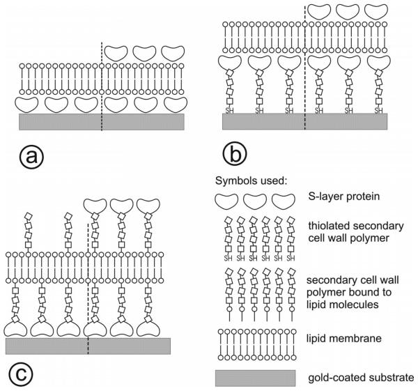
Since S-layer-supported and S-layer-stabilized lipid membranes represent supramolecular structures resembling the architecture of cell envelopes of gram-negative archaea, the proposed approach constitutes a biomimetic concept that opens up new avenues in basic and applied membrane science (Fig. 1).
FIG. 1.
Schematic of S-layer stabilized solid supported lipid membranes. In (a), the S-layer is directly recrystallized on the gold-coated surface. Subsequently, a lipid membrane can be formed, e.g., by the Langmuir-Schaefer technique. In (b), thiol-functionalized secondary cell wall polymers (SCWPs) are directly bound to the gold surface. On this biomimetic surface, S-layer proteins can be recrystallized and finally, a lipid membrane can be formed. In (c), the S-layer is directly recrystallized on the gold-coated surface. To take advantage of the S-layer protein, SCWP interaction, lipid-SCWP constructs are added to the membrane-forming lipid resulting in membranes anchored on the S-layer lattice and tethered by SCWP. As an option, on all three composite architectures, S-layer proteins can be recrystallized as a protecting coat with molecular sieve function.
Phospholipid bilayers or tetraether lipid monolayers provide a matrix for the reconstitution of functional molecules (e.g., ion channels, carriers, pore-forming proteins, proton pumps, etc.) which are key elements in the development of membrane-based bioanalytical sensors. Planar freestanding lipid membranes are highly susceptible to damage during manual handling procedures and prolonged storage, and are therefore usually not used for practical devices. Consequently, much effort has been directed to the development of stabilized or supported lipid membranes in order to increase their long-term functional stability. Recently, it was proposed to place a soft polymer cushion between the substrate (e.g., silica or Au) and the functional lipid membrane in order to maintain the thermodynamic and structural properties of the latter.19 This additional layer was also meant to act as a functional ionic reservoir and to provide the space and the environment for the incorporation of proteins in a well-defined orientation under nondenaturing conditions.20,21 Several approaches to stabilized integrated bilayers have been reported in the literature. These include bilayers with the inner monolayer covalently bound to the substrate with or without tether molecules,22-25 bilayers electrostatically attracted to the substrate, freely supported lipid bilayers separated from the substrate by ultrathin water layers, and bilayer membranes resting on ultrathin, soft hydrated polymer films.26-29
In this paper, we summarize some of our efforts toward constructing solid-supported functional lipid membranes. We describe some characteristic features of Langmuir monolayers of lipid systems at the water/air interface, compare the results with membranes tethered via flexible spacers to a solid support, and finally, describe experiments aimed at developing biomimetic membranes based on protein sheet crystals.
II. RESULTS AND DISCUSSION
A. Lipid monolayers at the water/air interface for the characterization of lipid-secondary cell wall polymer constructs
Accessory SCWP from Lysinibacillus sphaericus CCM 2177 and Geobacillus stearothermophilus PV72/p2 play a key role for a controlled recrystallization of the respective S-layer proteins, SbpA and SbpB. The N-terminal part of SbpA and SbsB comprises the typical S-layer homologous domain, which specifically recognizes the corresponding SCWP as binding site.30,31 The SCWPs are composed of disaccharide repeating units7 and contain pyruvate ketals which provide a net negative charge.9,31 SCWP2177 was isolated from peptidoglycan-containing sacculi of L. sphaericus CCM 2177 and was purified.31 Characterization of the isolated and highly pure SCWP2177 was performed with fluorescence assisted carbohydrate electrophoresis and high pressure liquid chromatography. Although the degree of polymerization (chain length) of SCWP2177 is very reproducible for the whole preparation, the polymer chains seem to be not homogeneously pyruvylated. Studies on the structure-function relationship revealed that up to 237 C-terminal amino acids from SbpA can be deleted without influencing the formation of the p4 lattice structure.30,32
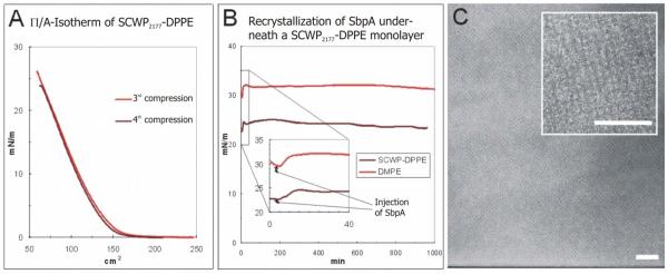
Chemical modification of the reducing end on the polymer chains was performed with the aim to introduce a terminal sulfhydryl group by modification with 2-iminothiolane.33 In a final step, the thiolated SCWP2177 was coupled to the phospholipid 1,2-dipalmitoyl-sn-glycero-3-phosphatidyl ethanolamin-N-[4-(p-maleimidophenyl)butyramid] (MPB-DPPE) to form the SCWP2177-DPPE conjugate. The coupling of SCWP with DPPE (1,2-dipalmitoyl-sn-glycero-3-phosphoethanolamine) is a key approach for fabricating supramolecular architectures since it allows to make a homogeneous SCWP-DPPE film at the air-water interface with the SCWP facing the subphase [Fig. 2(a)]. Comparative studies with 1,2-dimyristoyl-sn-glycero-3-phosphoethanolamine (DMPE) have also been performed [Fig. 2(b)]. The S-layer protein SbpA, isolated from L. sphaericus CCM 2177, was injected into the subphase and recrystallized at the SCWP2177-DPPE film. The inner face of SbpA (with respect to the native orientation on the bacterial cell) was found to be oriented toward the SCWP2177.
FIG. 2.
(Color online) (A) II/A-isotherm for 30 μg SCWP2177-DPPE. (B) II/time diagram for the recrystallization of S-layer protein from L. sphaericus (termed SbpA) at the SCWP2177-DPPE layer and a DMPE monolayer. (C) TEM images of a negatively stained preparation of SbpA-SCWP2177-DPPE. Bars (100 nm).
Finally, the composite SCWP2177-DPPE layer, or the S-layer protein-SCWP2177-DPPE architecture was deposited onto a solid substrate either by a Langmuir-Blodgett or a Langmuir-Schaefer transfer. In both cases, a crystalline S-layer lattice with a high degree of range order was found [Fig. 2(c)]. In particular, the use of genetically functionalized S-layer proteins will allow to “weave a protein carpet” which exhibits biological functionalities according to the lattice parameters of the S-layer.
B. Assembly of S-layer proteins onto solid supports
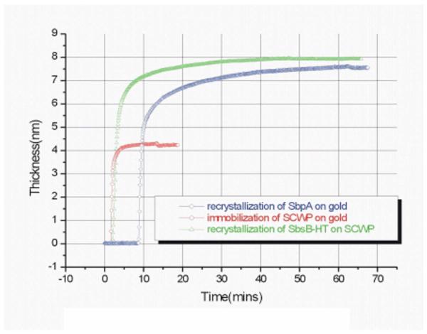
The assembly of S-layer proteins from solution to a solid substrate, in this case, a Au-coated glass slide, could be followed in-situ and in real time by surface plasmon resonance (SPR) spectroscopy. The substrate was mounted in a flow cell attached to the glass prism used in the Kretschmann configuration for the excitation of surface plasmon modes probing the noble metal/buffer interface.34 Figure 3 shows the formation (crystallization) of a monolayer of the S-layer protein SbpA directly onto the Au surface (blue curve). The thickness was calculated based on a refractive index of n =1.45 assumed for the protein layer. A complete monolayer with a thickness of d=8 nm, fully covering the substrate is obtained after 40 min.
FIG. 3.
(Color online) Assembly of S-layer proteins on a solid substrate.
A further powerful surface-sensitive technique to follow the S-layer self-assembly on solid surfaces in real time is quartz crystal microbalance (QCM) with dissipation monitoring (QCM-D).35,36 QCM is an ultrasensitive mass sensor that monitors the real-time change in adsorbed amount of material (including coupled water mass).37,38
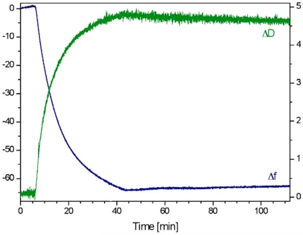
The S-layer protein SbpA has been recrystallized on silicon dioxide-coated sensor surfaces with a thickness of the SiO2 layer of 50 nm. The increase in mass per time has been investigated in-situ by a QCM-D device from Q-Sense (Fig. 4). The self-assembly of SbpA on SiO2 surfaces gave rise to a mass increase of 1050±70 ng/cm2 (n=8 independent measurements). In line with the SPR measurements, the self-assembly process is completed after approximately 45 min (Fig. 3). The protein mass of SbpA without the mass of coupled water was measured by SPR and was found to be between 620 and 650 ng/cm2.39 As it is obvious that S-layers are highly water-containing structures, the difference in QCM-D and SPR mass can be attributed to trapped water inside and coupled to the S-layer lattice. Using QCM-D and SPR in parallel thus gives an understanding of the complete self-assembly process. The mass increase of 1050 ng/cm2 corresponds to a thickness of 9.3±0.8 nm, as calculated by using the Sauerbrey equation40 and is in good agreement with the value obtained by SPR (Fig. 3). As the dissipation D increased to a final value of (4.8±0.3)×10−6 (n=8), the thickness, however, may be underestimated by the Sauerbrey equation and modeling studies are presently under progress.
FIG. 4.
(Color online) Changes in frequency (blue line) and dissipation (green line) vs time upon the self-assembly of the S-layer protein SbpA from L. sphaericus CCM 2177 on a silicon dioxide-covered QCM-D sensor.
Similarly, the formation of a well-defined monolayer of a SCWP by adsorption from solution could be followed by SPR spectroscopy (Fig. 3, red curve). By assuming a refractive index of the polymer of n=1.5, a thickness of the final coating of d=4.2 nm is found. Onto this, the corresponding S-layer protein SbsB readily forms a monolayer of also d =8 nm (Fig. 6, green curve). We should mention that this adsorption is completely specific, i.e., this SCWP layer is totally inert toward the injection of the S-layer protein SbpA.
FIG. 6.
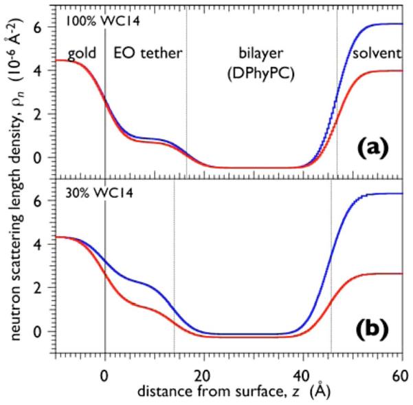
(Color online) Neutron SLD profiles along the surface normal, z, of tBLMs prepared on tethered SAMs that were adsorbed to 10 nm thick gold films by adsorption from organic solutions that contained WC14 only [panel (a)] and a 30:70 (mol:mol) mixture of WC14 and βME. The subsequent completion of the tBLMs with DPhyPC by rapid solvent exchange, i.e., incubation of the SAM with a highly concentrated ethanolic solution of the lipid, followed by the rapid replacement through injection of aqueous buffer (Ref. 46), was identically conducted in the two preparations. Note that the nSLD is almost identical in the submembrane space in panel (a) whereas it is distinct in panel (b).
C. S-layer stabilized lipid membranes
For S-layer stabilized lipid membrane (SsLM) formation, a sheet of polyethylene plastic was vertically attached to the open side of the homemade measuring chamber.41-43 The contact area between the sheet and the chamber was sealed with an O-ring previously treated with silicone paste. An orifice was made through the plastic sheet by punching with a perforating tool (0.4 mm in diameter). The orifices showed an area of approximately 10−3 cm2 as determined by light microscopy. An SbpA-coated gold substrate (test electrode) was placed over the aperture with the S-layer pointing toward the compartment. As shown in Fig. 1, SbpA may be directly recrystallized on the gold surface [Fig. 1(a)], or recrystallized on thiolated SCWP to utilize the specific SbpA-SCWP interaction for defined orientation and higher long-range order of the SbpA lattice [Fig. 1(b)]. Another approach based on the SbpA-SCWP interaction is to add lipid-SCWP constructs to the membrane-forming lipid to gain in stability of the composite layered architecture [Fig. 1(c)]. After mounting the substrate, the chamber was filled to just above (for phospholipids) or below (for tetraetherlipids) the aperture with electrolyte and was placed into a Faraday cage. Subsequently, 2 μl of the lipid dissolved in n-hexane/absolute ethanol (9:1, v/v; 0.5 mg/ml) was spread on the aqueous surface to form a lipid monolayer. The membranes were generated by a modified Langmuir-Blodgett technique by transferring the phospholipid monolayer twice over the aperture by lowering and raising the electrolyte level. With tetraetherlipids, simply one raising step of the lipid monolayer was sufficient. Interestingly, in contrast to other bilayer lipid membrane techniques, no pretreatment of the orifice with alkane or lipid was required.
SsLM formed by a modified Langmuir-Blodgett technique were investigated by electrochemical impedance spectroscopy (EIS).41 The specific capacitances of phospholipid bilayers and tetraetherlipid monolayers were 0.53 and 0.75 μF/cm2, respectively. Membrane resistances of up to 80 MΩ cm2 were observed for phospholipid bilayers resting on SbpA.41 In addition, membranes supported by a top layer of SbpA exhibited a remarkable long-term robustness of up to two days. More recent studies using tetraetherlipids as membrane-forming lipid demonstrated for SsLM with a S-layer cover a long-term robustness of approximately one week.
The functionality of lipid membranes resting on S-layer covered gold electrodes has been demonstrated by the reconstitution of membrane-active peptides such as alamethicin, gramicidin A, and valinomycin. For instance, due to the formation of conductive alamethicin channels, the membrane resistance (80 MΩ cm2) dropped approximately two orders of magnitude, whereas the capacitance was not altered.41 These present results obtained so far have proven that SsLM are promising structures for membrane protein-based biosensor technology.
D. Tethered bilayer lipid membranes (tBLMs)
The design of functional tethered bilayer membranes requires a deeper understanding of the molecular interactions that determine supramolecular organization at interfaces. One important aspect of the work reported here concerns the structural and functional organization of tBLMs at the molecular level. To this end, we synthesized the corresponding lipids, e.g., diphytanoyl-glycerol-tetraethyleneglycol lipoic acid,44,45 and tetradecyloxy-heptaoxahexatricontane-thiol (WC14),46,47 as well as used a commercial product with longer ethyleneglycol (EG) chains, Avanti Polar Lipids DSPE-PEG-PDP, Cat. No. 880127 [distearoylphosphatidylethanolamine (DSPE); pyridyldithio-propionate (PDP)].
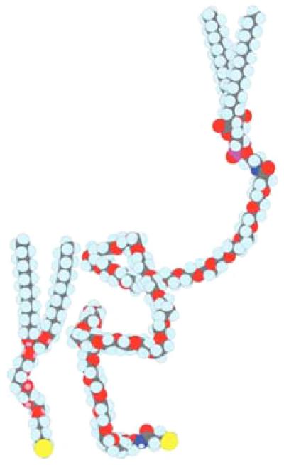
The common theme of these molecules that serve as tethering anchors for the tBLM architectures become apparent in Fig. 5. All of the organic structures were formed on atomically flat gold substrates, sputtered upon Si wafers on top of a Cr layer necessary for bonding the gold film to the Si substrate. Typical rms roughness values of the Au surfaces, measured within the μm-sized in-plane coherence by x-ray reflectometry, were on the order of 5 Å. These surfaces were uniform as measured by ellipsometry across the 75 mm wafers required for neutron scattering investigations, and were typically between 100 and 200 Å thick. Samples for EIS and optical characterization were typically 20×40 mm2 in area. They were sputtered with thicker gold layers (typically 100 nm) and supported a number of parallel experiments, e.g., six independently prepared tBLM areas for EIS measurements. Details of the substrate preparations have been described in Ref. 46.
FIG. 5.
(Color online) Molecular models of chemical compounds investigated as a basis for tBLMs: WC14 (left) and DSPE-PEG-PDP (right).
The rationale for including a hydrophilic polymer, such as an oligo(EG), between a reactive thiol or mercapto group and the lipid anchor is to engineer a molecularly thin, disjoining layer between the inorganic solid state surface and the bilayer membrane which is highly hydrated, stable, and uniform in thickness. This submembrane space ensures that the lipid membrane is not immobilized by direct molecular interactions with the substrate and, if sufficiently thick, provides space to accommodate hydrophilic segments of trans-membrane proteins incorporated into the tBLMs for their functionalization. Specifically, with WC14 as the membrane anchor, we established a protocol that consists of self-assembly of a mixed monolayer of the thiolated tether lipid with a “backfiller,” followed by bilayer completion with phospholipids in a “rapid solvent exchange” procedure.25 This protocol results in high-quality, electrically insulating membranes with a number of compositions, ranging from branched (phytanoyl) via saturated (palmitoyl, myristoyl) to unsaturated (oleoyl). Both zwitterionic (phosphocholine) and anionic (phosphoglycerol) head groups, as well as cholesterol, were incorporated into tBLMs. While the submembrane space in similar systems has previously not been systematically investigated on the molecular scale, the advancement of neutron scattering technology in recent years48 has made such a detailed characterization available.
Hydration of the submembrane space critically depends on the formation of the self-assembled monolayer (SAM) by coadsorption of WC14 together with a short, hydrophilically terminated backfiller, β-mercaptoethanol (βME).46 Figure 6 shows neutron reflectivity results that compare structures at different solvent contrasts in which the tBLMs were based on SAMs adsorbed from a solution of pure WC14 (upper frame) and of a 30:70 (mol:mol) mixture of WC14 with βME (lower frame). It is evident that the neutron scattering length density (nSLD) in the region of the submembrane space changes upon exchange of the solvent (pure D2O against a H2O/D2O mixture) in the case of the WC14:βME-based tBLMs, whereas the nSLD remains constant underneath the membrane based upon pure WC14. Quantitative evaluation of such nSLD variations enable a precise determination of the solvent content in this layer, which may reach ~60% by volume at high βME proportions in the adsorption solution.46 The hexaethyleneoxide tether is fairly extended in the tBLMs (dtBLM~17–13 Å, with smaller thicknesses at higher βME proportions/higher hydrations while the extended length is estimated from the molecular model as dext~20 Å). Particularly, in SAMs from high proportions of βME, bilayer completion through vesicle fusion does not work, since the SAM surface in air is rather hydrophilic,46 but works rather well through rapid solvent exchange. As judged by neutron reflectometry, such bilayers are nearly 100% complete (with a typical error of this number in the range of 2%–3%).
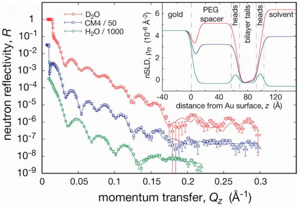
With the tether lipids that contain oligo(EG), which have been discussed so far, the thin submembrane layer (d <20 Å) may not be sufficient to accommodate membrane proteins with large hydrophilic domains on both sides of the biomembrane. We have therefore also studied tBLMs based upon DSPE-PEG2000-PDP, where the spacer incorporates ~45 EG repeats. Preparation procedures generally followed those described above. No backfilling was necessary to obtain a well-hydrated submembrane compartment (see below). Following SAM formation, the water contact angle was in the range of 70° –90°. Despite this low hydrophobicity, tBLMs were formed with rapid solvent exchange by using diphytanoylphosphatidylcholine (DPhyPC) or dioleoylphosphatidylcholine (DOPC), and were subjected to characterization with neutron reflectometry (see Fig. 7 for a sample completed with DPhyPC). However, tBLMs prepared in this way were not sufficiently electrically insulating for characterization with EIS. Figure 5 demonstrates that the rapid solvent exchange procedure produces structurally intact and laterally homogeneous and complete tBLMs on DSPE-PEG-PDP SAMs. A fairly complex model, which incorporates nine layers, describes the three independent spectra quite well over the entire range of momentum transfer covered in the measurements. Note that not all model parameters have been fitted, since the substrate components have well-established nSLD parameters, and that the three contrasts, measured on the same sample after replacing the solvent with buffer of various isotopic compositions, are coupled in a composition-space refinement evaluation.49-51 For this evaluation, the ga_refl implementation52 was used.
FIG. 7.
(Color online) Neutron reflection (three solvent contrasts; “CM4” is a H2O/D2O mixture with with ρn=4×10⁻⁶ Å−2) of a tBLM based on DSPE-PEG-PDP and completed with DPhyPC. For details, see text.
The most striking distinction of the nSLD profiles shown in the inset of Fig. 7 to those typical of tBLMs based on oligo(EG) concerns the submembrane space which is d ~60 Å in thickness. Not surprisingly, it is highly hydrated (note the only slight differences between the nSLD values in the submembrane space and the bulk for each contrast) and contains >70% water by volume. Apparently, the chain conformations are quite disordered (extended length, dext ~160 Å for n=45), and therefore the observed thickness of the submembrane space is closer to the polymer's gyration diameter (2RG~69 Å) than to dext. It is also obvious that the distribution of EG segments is not homogeneous along the surface normal. We have not been able to model the experimental data with one slab for the submembrane space. Rather, there appears to be a thin (d~10 Å), EG-dense (60 vol %) region close to the gold surface while a 50 Å thick slab close to the membrane appears reasonably homogeneous and highly hydrated (~80% water). According to the best-fit model, ~30% of the EG repeat units are adsorbed to the gold surface.
The bilayer structure centered at z~80 Å is fairly complete. The model suggests a coverage of the available surface area that amounts to 100% for the inner bilayer leaflet and 97% for the outer. Uncertainties in these numbers are ±3%. While the solvent contrast based on H2O does not contribute much information about the hydrophobic lipid slab, it is invaluable to discriminate the lipid head group features in the structure (see features in the nSLD profile centered at z ~63 and 98 Å). By exploiting such structural detail, one may thus speculate that upon incorporation of transmembrane proteins, neutron scattering might be able to reveal changes in the distribution of lipid head groups along the surface normal in response to its accommodation of the protein, particularly if isotopic labeling of head group components is used. Recent success in incorporating protein toxin pores into tBLMs at high lateral concentrations53 has been an encouraging first step in this direction.
Sparsely tethered BLMs provide a simple, but highly flexible and robust biomimetic membrane system for studies and applications of biological membranes. In our laboratory, such tBLMs are now being used to investigate the molecular organization of protein toxin pores in membranes53 and to study toxicity mechanisms of β-amyloid oligomers54 implicated in Alzheimer's disease. The tBLMs are long-term stable, electrically sealing, and laterally homogeneous on the molecular length scale. The protocol is currently being extended to the preparation of mixed membranes and to surfaces with controlled charge density. The approach can be scaled to large and small surface areas. The two-step formation of the bilayer membrane (producing first a stable SAM, followed by noncovalent membrane completion with any from a range of saturated and unsaturated lipids, or lipid mixtures) and reversibility of membrane formation by solvent rinsing imply that SAMs may be recycled and reused. The robustness and flexibility of the system make it amenable to various characterization techniques, and also make it potentially useful in many biomimetic metrologies, including biosensors.
E. Simulation of the ion translocation across tBLMs
The successful assembly of complex tethered and/or S-layer protein supported bilayer lipid membranes is a prerequisite for the next step toward membrane-based biosensors, i.e., their functionalization by ion translocating ionophores or proteins. This has been shown for the reconstitution of valinomycin and alamethicin.
The specific constraints of such an interfacial architecture assembled on a solid substrate for the distribution of ions and water molecules near and across the tethered/supported membrane and, in particular, the very limited space in the cleft between the bilayer and the solid support influence the electrical/electrochemical response of such an architecture to (external) changes in the ionic concentrations in the attached flow cell by the application of an external voltage (with the substrate being the working electrode and a reference electrode positioned somewhere in the buffer solution), or as a consequence of the ion translocation activity of the incorporated active elements, e.g., the (gated) opening and closing of a channel structure.
In a classical simulation approach, this response is described by calculating the current passing through a circuitry composed of a minimal number of passive elements, typically resistors and capacitors, as a function of the applied voltage with variable elements, until a satisfactory description of the experimentally observed behavior is reached. The required elements are then interpreted as the representations of the various features of the interfacial architecture. For example, the lipid bilayer is described by a parallel arrangement of a capacitor and an Ohmic resistor, while the tethering layer is a mere capacity and the bulk electrolyte a resistor, both in series to the bilayer membrane.
A limitation of simulating EIS data with purely passive circuit elements is the difficulty to accurately describe kinetic features related to ion transport across the membrane through either membrane permeation or more complicated transport mechanisms such as the ion-shuttle mechanism proposed for valinomycin.55
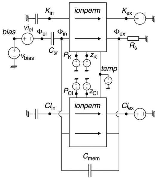
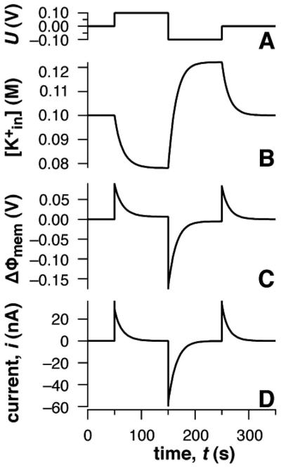
Therefore, we started to develop and to apply a different approach, based on a code developed for general network analysis, called SPICE.56 Figure 8 displays a schematic representation of elements of such a network needed to describe the passive permeation of ions across a lipid bilayer tethered to a solid support. Traditional passive elements are used to represent storage components, such as the membrane capacitance (Cmem) and the double-layer capacitance (Csr), and bulk ionic diffusion is represented by a simple resistance (Rex). The subcircuit represented by ionperm describes the permeation of ions generating an ionic current as a response to the concentration difference between ion (i.e., Cl− or K+) across the membrane, and the difference of the potential across the lipid bilayer, ΔΦmem=Φin−Φex. This current contribution is calculated within the simulation by solving the integrated Nernst-Planck flux equation correlating the flux of K+ ions to the passive permeability and the gradient of electrochemical potentials across the membrane. The corresponding subcircuit can simply be treated as a plug-in module to the basic network used then to calculate the complete current, composed of charging contributions and ion permeation. Greater detail about the simulations can be found in Ref. 57.
FIG. 8.
Circuit elements for the SPICE simulation of the passive ion permeation across a solid-supported lipid bilayer membrane.
Figure 9 displays the result of such a simulation with the membrane in a 100 mM KCl electrolyte solution. Under the simplifying assumption that K+ ions are the only species redistributing between the bulk of the solution and the submembrane space, and assuming a K+ permeability across the membrane of PK+=10−9 cm/s, the electronic and ionic response to the applied potential is displayed. At t=0, with U=0 V, both the membrane potential drop and ionic current vanish, because (=0.1 M). When the potential is stepped to U= +100 mV, the potential drop initially occurs entirely across the membrane. Subsequently, K+ ions electrodiffuse across the membrane with a relaxation time proportional to the membrane permeability. The new steady state is characterized by an internal ion concentration, mM, and a transmembrane potential of ΔΦmem ≈6 mV. Ion diffusion is associated with a transient current across the membrane which decays to zero with the same relaxation time. Subsequent voltage jumps to U=−100 mV and back to 0 V are followed by analogous changes in ion concentration, membrane potential, and transmembrane current.
FIG. 9.
SPICE simulations of a simplified tethered bilayer membrane with K+ ions as the only mobile species. (A) Applied potential ΔU, (B) ion concentration the submembrane space between the membrane and the solid substrate, (C) transmembrane potential ΔΦmem, and (D) net ionic current responses to the applied potential are shown as a function of time. Input parameters in the simulation are Csr=5 μF, Cmem=0.67 μF, Rs=50 Ω, volume of the tether: 22 nL and PK+=10−9 cm/s.
III. CONCLUSIONS AND OUTLOOK
The presented results clearly document that the use of the S-layer proteins as building blocks in the assembly of functional solid supported lipid bilayer membranes results in architectures with an enhanced functional performance in combination with a better structural robustness and stability beyond the properties of the mere tethered bimolecular lipid membrane. This opens the way for novel strategies in the development of artificial membrane biosensor platforms by combining natural elements such as the S-layer proteins with artificially modified modules, e.g., thiolated SCWP or even with fully synthetic construction blocks such as ethylene oxide tethered amphiphiles. The described elements of a whole construction kit allow for a broad range of tailor-made membrane architectures purposefully customized for specific applications. This could be the design of an optimized charge barrier with extremely low background conductivity for the recording of single channel current fluctuations, or a supported membrane with an uncompromised fluidity for studies of the lateral aggregation of membrane-integral proteins. The various examples given demonstrate that we are getting closer to a better understanding of the important factors that determine the structural and functional features of supported lipid bilayers and, hence, their successful implementation in a membrane chip, complementing the gene and protein array, for multiplexed detection of analytes, e.g., drug targeting membrane receptors.
ACKNOWLEDGMENTS
Financial support from the Volkswagen Stiftung (Project No. I/77708–10) is gratefully acknowledged. Part of this work was also funded by the Austrian Science Fund (Project Nos. 16295-B10 and 20256-B11), the Austrian Federal Ministry of Transport, Innovation and Technology (Grant No. BMVIT-612.005/004-III/I1/2005), the National Science Foundation (Grant No. CBET 0522201), the American Health Assistance Foundation (Grant No. A2008–307), the NIH (Grant No. P01AG032131–01), and the U.S. Air Force Office of Scientific Research (Project No. F49620-03-1-0222). Helpful discussions with I. Köper, D. Walz, G. Valincius, D. J. Vanderah, and J. J. Kasianowicz are gratefully acknowledged.
References
- 1.Sleytr UB, Messner P, Pum D, Sára M, editors. Crystalline Bacterial Cell Surface Proteins. R. G. Landes/Academic; Austin, TX: 1996. [Google Scholar]
- 2.Sleytr UB, Beveridge TJ. Trends Microbiol. 1999;7:253. doi: 10.1016/s0966-842x(99)01513-9. [DOI] [PubMed] [Google Scholar]
- 3.Sleytr UB, Sára M, Pum D, Schuster B. In: Supramolecular Polymers. 2nd ed. Ciferri A, editor. CRC, Boca Raton, FL/Taylor & Francis; London: 2005. pp. 583–616. [Google Scholar]
- 4.(a) Sleytr UB, Messner D, Pum D, Sára M. Angew. Chem., Int. Ed. 1999;38:1034. doi: 10.1002/(SICI)1521-3773(19990419)38:8<1034::AID-ANIE1034>3.0.CO;2-#. [DOI] [PubMed] [Google Scholar]; (b) Sleytr UB, Huber C, Ilk N, Pum D, Schuster B, Egelseer EM. FEMS Microbiol. Lett. 2007;267:131. doi: 10.1111/j.1574-6968.2006.00573.x. [DOI] [PubMed] [Google Scholar]; (c) Sleytr UB, Egelseer EM, Ilk N, Pum D, Schuster B. FEBS J. 2007;274:323. doi: 10.1111/j.1742-4658.2006.05606.x. [DOI] [PubMed] [Google Scholar]
- 5.Sára M, Sleytr UB. J. Bacteriol. 1987;169:2804. doi: 10.1128/jb.169.6.2804-2809.1987. [DOI] [PMC free article] [PubMed] [Google Scholar]
- 6.Ries W, Hotzy C, Schocher I, Sleytr UB. J. Bacteriol. 1997;179:3892. doi: 10.1128/jb.179.12.3892-3898.1997. [DOI] [PMC free article] [PubMed] [Google Scholar]
- 7.Sàra M, Dekitsch C, Mayer HF, Egelseer EM, Sleytr UB. J. Bacteriol. 1998;180:4146. doi: 10.1128/jb.180.16.4146-4153.1998. [DOI] [PMC free article] [PubMed] [Google Scholar]
- 8.Sàra M, Egelseer EM, Dekitsch C, Sleytr UB. J. Bacteriol. 1998;180:6780. doi: 10.1128/jb.180.24.6780-6783.1998. [DOI] [PMC free article] [PubMed] [Google Scholar]
- 9.Schäffer C, Messner P. Microbiology. 2005;151:643. doi: 10.1099/mic.0.27749-0. [DOI] [PubMed] [Google Scholar]
- 10.Sleytr UB, Messner P. In: Electron Microscopy of Subcellular Dynamics. Plattner H, editor. CRC, Boca Raton; FL: 1989. pp. 13–31. [Google Scholar]
- 11.Pum D, Weinhandl M, Hödl C, Sleytr UB. J. Bacteriol. 1993;175:2762. doi: 10.1128/jb.175.9.2762-2766.1993. [DOI] [PMC free article] [PubMed] [Google Scholar]
- 12.Pum D, Sleytr UB. Supramol. Sci. 1995;2:193. [Google Scholar]
- 13.Mader C, Küpcü S, Sára M, Sleytr UB. Biochim. Biophys. Acta. 1999;1418:106. doi: 10.1016/s0005-2736(99)00030-9. [DOI] [PubMed] [Google Scholar]
- 14.Schuster B, Pum D, Sleytr UB. Biochim. Biophys. Acta. 1998;1369:51. doi: 10.1016/s0005-2736(97)00206-x. [DOI] [PubMed] [Google Scholar]
- 15.Schuster B, Sleytr UB. Mol. Biotechnol. 2000;74:233. doi: 10.1016/s1389-0352(00)00014-3. [DOI] [PubMed] [Google Scholar]
- 16.Schuster B, Sleytr UB. In: Advances in Planar Lipid Bilayers and Liposomes. Tien HT, Ottova A, editors. Vol. 1. Elsevier, Amsterdam; The Netherlands: 2005. pp. 247–293. [Google Scholar]
- 17.Schuster B. Nanobiotechnol. 2005;1:153. [Google Scholar]
- 18.Schuster B, Sleytr UB. Curr. Nanosci. 2006;2:143. [Google Scholar]
- 19.Sackmann E. Science. 1996;271:43. doi: 10.1126/science.271.5245.43. [DOI] [PubMed] [Google Scholar]
- 20.Florin EL, Gaub HE. Biophys. J. 1993;64:375. doi: 10.1016/S0006-3495(93)81378-X. [DOI] [PMC free article] [PubMed] [Google Scholar]
- 21.Raguse B, Braach-Maksvytis VLB, Cornell BA, King LB, Osman PDJ, Pace RJ, Wieczorek L. Langmuir. 1998;14:648. [Google Scholar]
- 22.Lang H, Duschl C, Vogel H. Langmuir. 1994;11:197. [Google Scholar]
- 23.Plant AL. Langmuir. 1993;9:2764. [Google Scholar]
- 24.Spinke J, Yang J, Wolf H, Liley M, Ringsdorf H, Knoll W. Biophys. J. 1992;63:1667. doi: 10.1016/S0006-3495(92)81742-3. [DOI] [PMC free article] [PubMed] [Google Scholar]
- 25.Cornell BA, Braach-Maksvytis V, King LG, Osman PD, Raguse B, Wieczorek L, Pace RJ. Nature (London) 1997;387:580. doi: 10.1038/42432. [DOI] [PubMed] [Google Scholar]
- 26.Groves JT, Ulman N, Boxer SG. Science. 1997;275:651. doi: 10.1126/science.275.5300.651. [DOI] [PubMed] [Google Scholar]
- 27.Seifert K, Fendler K, Bamberg E. Biophys. J. 1993;64:384. doi: 10.1016/S0006-3495(93)81379-1. [DOI] [PMC free article] [PubMed] [Google Scholar]
- 28.Steinem C, Janshoff A, Ulrich WP, Sieber M, Galla HJ. Biochim. Biophys. Acta. 1996;1279:169. doi: 10.1016/0005-2736(95)00274-x. [DOI] [PubMed] [Google Scholar]
- 29.Stelzle M, Weissmüller G, Sackmann E. J. Phys. Chem. 1993;97:2974. [Google Scholar]
- 30.Huber C, Ilk N, Rünzler D, Egelseer EM, Weigert S, Sleytr UB, Sára M. Mol. Microbiol. 2005;55:197. doi: 10.1111/j.1365-2958.2004.04351.x. [DOI] [PubMed] [Google Scholar]
- 31.Ilk N, Kosma P, Puchberger M, Egelseer EM, Mayer HF, Sleytr UB, Sára M. J. Bacteriol. 1999;181:7643. doi: 10.1128/jb.181.24.7643-7646.1999. [DOI] [PMC free article] [PubMed] [Google Scholar]
- 32.Sára M. Trends Microbiol. 2001;9:47. doi: 10.1016/s0966-842x(00)01905-3. [DOI] [PubMed] [Google Scholar]
- 33.Mader C, Huber C, Moll D, Sleytr UB, Sára M. J. Bacteriol. 2004;186:1758. doi: 10.1128/JB.186.6.1758-1768.2004. [DOI] [PMC free article] [PubMed] [Google Scholar]
- 34.Knoll W. Annu. Rev. Phys. Chem. 1998;49:569. doi: 10.1146/annurev.physchem.49.1.569. [DOI] [PubMed] [Google Scholar]
- 35.Cooper MA, Singleton VT. J. Mol. Recognit. 2007;20:154. doi: 10.1002/jmr.826. [DOI] [PubMed] [Google Scholar]
- 36.Keller CA, Kasemo B. Biophys. J. 1998;75:1397. doi: 10.1016/S0006-3495(98)74057-3. [DOI] [PMC free article] [PubMed] [Google Scholar]
- 37.Höök F, Rodahl M, Kasemo B, Brzezinski P. Proc. Natl. Acad. Sci. U.S.A. 1998;95:12271. doi: 10.1073/pnas.95.21.12271. [DOI] [PMC free article] [PubMed] [Google Scholar]
- 38.Rodahl M, Höök F, Krozer A, Brzezinski P, Kasemo B. Rev. Sci. Instrum. 1995;66:3924. [Google Scholar]
- 39.Pisecker M. Universität für Bodenkultur; Vienna: 2005. Diploma thesis. [Google Scholar]
- 40.Sauerbrey G. Z. Phys. 1959;155:206. [Google Scholar]
- 41.Gufler PC, Pum D, Sleytr UB, Schuster B. Biochim. Biophys. Acta. 2004;1661:154. doi: 10.1016/j.bbamem.2003.12.009. [DOI] [PubMed] [Google Scholar]
- 42.Schuster B, Pum D, Sára M, Braha O, Bayley H, Sleytr UB. Langmuir. 2001;17:499. [Google Scholar]
- 43.Schuster B, Weigert S, Pum D, Sára M, Sleytr UB. Langmuir. 2003;19:2392. [Google Scholar]
- 44.Naumann R, Schiller SM, Giess F, Grohe B, Hartman KB, Karcher I, Köper I, Lubben J, Vasilev K, Knoll W. Langmuir. 2003;19:5435. [Google Scholar]
- 45.Schiller SM, Naumann R, Lovejoy K, Kunz H, Knoll W. Angew. Chem., Int. Ed. 2003;42:208. doi: 10.1002/anie.200390080. [DOI] [PubMed] [Google Scholar]
- 46.McGillivray DJ, Valincius G, Vanderah DJ, Febo-Ayala W, Woodward JT, Heinrich F, Kasianowicz JJ, Lösche M. BioInterphases. 2007;2:21. doi: 10.1116/1.2709308. [DOI] [PubMed] [Google Scholar]
- 47.Valincius G, McGillivray DJ, Febo-Ayala W, Vanderah DJ, Kasianowicz JJ, Lösche M. J. Phys. Chem. B. 2006;110:10213. doi: 10.1021/jp0616516. [DOI] [PubMed] [Google Scholar]
- 48.Dura JA, Pierce D, Majkrzak CF, Maliszewskyj N, McGillivray DJ, Lösche M, O'Donovan KV, Mihailescu M, Perez-Salas UA, Worcester DL, White SH. Rev. Sci. Instrum. 2006;77:074301. doi: 10.1063/1.2219744. [DOI] [PMC free article] [PubMed] [Google Scholar]
- 49.Heinrich F, Ng T, Vanderah DJ, Shekhar P, Mihailescu M, Nanda H, Lösche M. Langmuir. 2009;25 doi: 10.1021/la8033275. in press. [DOI] [PubMed] [Google Scholar]
- 50.Vaknin D, Kjaer K, Als-Nielsen J, Lösche M. Biophys. J. 1991;59:1325. doi: 10.1016/S0006-3495(91)82347-5. [DOI] [PMC free article] [PubMed] [Google Scholar]
- 51.Wiener MC, White SH. Biophys. J. 1991;59:174. doi: 10.1016/S0006-3495(91)82209-3. [DOI] [PMC free article] [PubMed] [Google Scholar]
- 52.Kienzle PA, Doucet M, McGillivray DJ, O'Donovan KV, Berk NF, Majkrzak CF. 2000–2009. ga_refl. http://www.ncnr.nist.gov/reflpak/garefl.html.
- 53.McGillivray DJ, Heinrich F, Ignatiev I, Vanderah DJ, Kasianowicz JJ, Valincius G, Lösche M. Biophys. J. in press. [Google Scholar]
- 54.Valincius G, Heinrich F, Budvytyte R, Vanderah DJ, McGillivray DJ, Sokolov Y, Hall JE, Lösche M. Biophys. J. 2008;95:4845. doi: 10.1529/biophysj.108.130997. [DOI] [PMC free article] [PubMed] [Google Scholar]
- 55.Naumann R, Walz D, Schiller SM, Knoll W. J. Electroanal. Chem. 2003;550–551:241. [Google Scholar]
- 56.Walz D, Caplan SR, Scriven DRL, Miculecky DC. In: Bioelectrochemistry: Principles and Practice. Caplan SR, Miller IR, Milazzo G, editors. Vol. 1. Birkhäuser; Basel: 1995. Chap. 2. [Google Scholar]
- 57.Robertson JWF, Friedrich MG, Lubrom A, Knoll W, Naumann RLC, Walz D. J. Phys. Chem. B. 2008;112:10475. doi: 10.1021/jp800162d. [DOI] [PubMed] [Google Scholar]


