Abstract
Multisource cone-beam computed tomography (CT) is an attractive approach of choice for superior temporal resolution, which is critically important for cardiac imaging and contrast enhanced studies. In this paper, we present a filtered-backprojection (FBP) algorithm for triple-source helical cone-beam CT. The algorithm is both exact and efficient. It utilizes data from three inter-helix PI-arcs associated with the inter-helix PI-lines and the minimum detection windows defined for the triple-source configuration. The proof of the formula is based on the geometric relations specific to triple-source helical cone-beam scanning. Simulation results demonstrate the validity of the reconstruction algorithm. This algorithm is also extended to a multisource version for (2N + 1)-source helical cone-beam CT. With parallel computing, the proposed FBP algorithms can be significantly faster than our previously published multisource backprojection-filtration algorithms. Thus, the FBP algorithms are promising in applications of triple-source helical cone-beam CT.
Index Terms: Computed tomography (CT), cone-beam, filtered-backprojection (FBP), helical scanning, triple-source
I. Introduction
The recently introduced Siemens’ dual-source computed tomography (CT) allows much-improved temporal resolution, and has received a major attention in the medical imaging field. A natural extension of the dual-source system is a triple-source cone-beam CT (CBCT) scanner for even better temporal resolution at an additional system cost. As a follow-up to our previously published work on backprojection-filtration (BPF) based triple-source CBCT, this paper presents an exact filtered-backprojection (FBP) algorithm for triple-source helical CBCT, which can be implemented using parallel-computing techniques much more efficiently than the BPF counterpart.
Many exact and efficient methods were developed for spiral/helical cone-beam CT over past years [1]–[15]. The focus loci range from specific to more general, and from single-source scanning to multisource configurations. In 2002, Katsevich introduced an exact filtered-backprojection (FBP) algorithm [1]. Then, Zou and Pan presented an exact backprojection-filtration (BPF) algorithm [2]. These algorithms utilize projection data from a PI-arc based on the so-called PI-line [16] and Tam–Danielsson window [16], [17]. The Katsevich FBP algorithm uses a 1-D Hilbert transform of derivatives of differential projection data within a window slightly larger than the Tam–Danielsson window. The merit of the Zou–Pan’s BPF formula is that it uses only the data in the Tam–Danielsson window and accommodates certain types of transverse data truncation.
To extend these results to the case of general scanning trajectories, Katsevich also presented a general scheme for constructing inversion algorithms [3]. Ye et al. [4], [5] proved the validity of the BPF formula in the case of a general scanning curve and derived a general Katsevich-type FBP formula [6]. Pack et al. [7], [8] also introduced the BPF and FBP formulas that can deal with discontinuous source curves. Other independent algorithms on general CBCT were also reported [46], [47]. Chen [9] gave an alternative derivation of the Katsvich cone-beam reconstruction formula based on the Tuy inversion formula [18]. Also, based on the Tuy formula, Zhao, Yu and Wang [10], [11] unified the above FBP and BPF formulas using appropriate operators.
Cardiac imaging and contrast enhanced studies are very important medical CT applications. Rapid data collection and exact reconstruction are highly desirable in the clinical settings. One approach to improve CT temporal resolution is to apply a half-scan technique [19]–[21]. However, further reduction of the source angular range is not generally possible since the data sufficiency condition [18] cannot be satisfied by a dataset less than a half-scan. Another approach is to use a multisource system [21]–[27], [12]–[15]. Theoretically, higher temporal resolution can be achieved as the number of sources becomes larger. The initial experience with the commercial dual-source CT system has been very encouraging in cardiac imaging and coronary angiography, which show that the dual-source CT generates high quality images with ultra high temporal resolution, making functional evaluation of the heart valves and myocardium clinically possible [23]–[26].
Unlike previous multisource systems that use either a circle scanning locus or an approximate reconstruction algorithm [21], [22], for the first time we recently proposed a generic design for exact triple-source helical CBCT [12]–[15]. Such an exact BPF reconstruction algorithm for triple-source helical CBCT [14], [15] was developed based on the Zhao window [12], [13] and the inter-helix PI-lines [12], [13]. The Zhao window is the minimum detection window for triple-source helical CBCT, which is a counterpart of the Tam–Danielsson window. Also, the role of the inter-helix PI-lines in triple-source helical CBCT is similar to that of the PI-lines in single source helical CBCT.
In this paper, we present an exact FBP algorithm for triple-source helical CBCT. The algorithm also uses data from the three inter-helix PI-arcs associated with the inter-helix PI-lines and corresponding Zhao windows. In comparison with our previous triple-source BPF algorithm, this triple-source FBP algorithm is advantageous in terms of image reconstruction speed when the parallel implementation is in place. Therefore, this algorithm is technically and clinically very attractive. The paper is organized as follows. In Section II, the FBP formula is derived by the roadmap in [10]–[13], [48], [49] and the geometric relations specific to triple-source helical CBCT. Section III describes the simulation results. In Section IV, relevant issues are discussed and conclusions are drawn.
II. FBP Formula for Triple-Source CBCT
Let a trajectory Γ be a piecewise differentiable curve in ℝ3 described by a(t), t ∈ ℝ, and f an infinitely differentiable real integrable function with a compact support Ω ⊂ ℝ3\Γ. ℝ3\Γ is the difference of sets ℝ3 and Γ. The cone-beam transform  f along Γ is defined by
| (1) |
where θ is the direction of a ray emitted from the source a,  2 = {(x,y,z) ∈ ℝ3, x2 + y2 + z2 = 1}.
Let f(x) be an object density function to be reconstructed. Assume that this function is smooth and vanishes outside the object cylinder
| (2) |
where Ro is the radius of the object cylinder and R the radius of the scanning cylinder. The scanning cylinder refers to the cylindrical volume confined by the helices defined by (3).
In the Cartesian coordinate system (x,y,z), the triple-helix trajectories can be expressed as
| (3) |
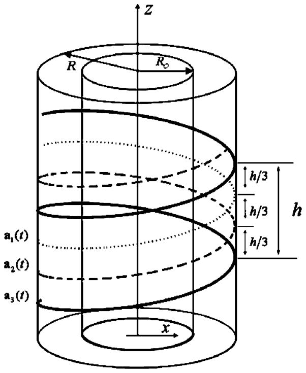
where R stands for the distance from each X-ray source to the rotation axis (i.e., the z-axis), h the pitch of each helix, and t the rotation angle. Fig. 1 illustrates the triple-source helical CBCT configuration.
Fig. 1.
Illustration of a triple-source helical cone-beam scanning. The three X-ray sources are rotated around the z-axis along the helices a1(t), a2(t), and a3(t), respectively. The helices a1(t), a2(t), and a3(t) are on a cylinder of radius R. An object to be reconstructed is confined within a cylinder of radius R0, where radius R0 < R. Parameter h denotes the pitch of each helix. The inter-helix distance along the z-axis is h/3 between neighboring helices.
Previously, we defined the inter-helix PI-lines and extended the traditional Tam–Danielsson window into the Zhao window in the case of triple helices [12], [13]. For convenience, here we restate the Zhao window as follows: for each source aj(t), the corresponding Zhao window is the region on the surface of the scanning cylinder bounded by the nearest helix turn of ajmod3+1(t) and the nearest helix turn of a(j+1)mod3+1(t), j ∈ {1, 2,3}[12], [13]. More specific definition of the Zhao Window is listed in Appendix II. Also, recall that an inter-helix PI-line for aj(t) and ajmod3+1(t), j ∈ {1, 2, 3}, is the line that (1) intersects aj(t) at one point and ajmod3+1(t) at the other point, (2) the absolute difference of the angular parameter values at the two intersection points is less than 2π [12], [13]. The definition of inter-helix PI-line is given in Appendix I. In fact, the inter-helix PI-lines are a type of R-lines [7], [28]. We already proved the existence and uniqueness properties of the inter-helix PI-lines, which can be summarized as the following theorem [12], [13]:
Theorem 1
Through any fixed x ∈ Ω, there exists one and only one inter-helix PI-line for any pair of the helices from the three helices defined by (3).
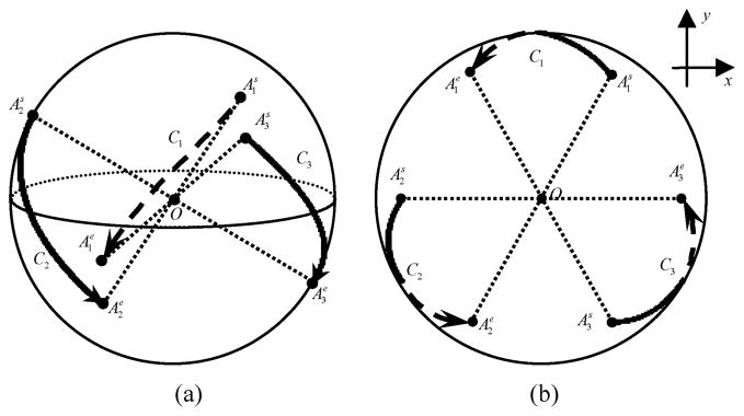
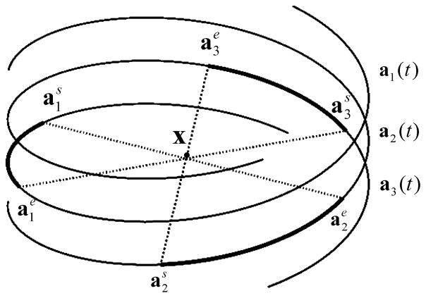
In the triple-helix case, there are three inter-helix PI-lines for a fixed x ∈ Ω and three corresponding inter-helix PI-arcs whose end points are the intersection points of the inter-helix PI-lines with the corresponding helices. The three inter-helix PI-arcs represent the source trajectory segments from which the sources illuminate the point x. Without loss of generality, we assume that the sources and the detectors are translated upwards and rotated counter-clockwise when being observed from the top. To describe the data completeness condition for a fixed x ∈ Ω, we use the Orlov method, i.e., consider direction curves on the unit sphere [29]. As shown in Fig. 2, the direction curves Cj, j ∈ {1, 2, 3}, on the unit sphere centered at x ∈ Ω correspond to the source scanning angular ranges for x (refer to [12], [13] for details). It is a property of the inter-helix PI-line for aj(t) and ajmod3+1(t) that the intersection points represent the beginning position of the source illuminating x from aj(t) and the end position of the other source illuminating x from ajmod3+1(t), j ∈ {1,2,3}[12], [13]. We denote the intersection points as and respectively. For brevity, we use the notations and . Then, the inter-helix P-line for and can be represented as . The intersection points and are mapped onto the unit sphere for x as and respectively, for j ∈ {1, 2,3}, as shown in Fig. 2. and are the start point and end point of Cj respectively. Next, we define the inter-helix PI-intervals for x ∈ Ω. In fact, the inter-helix PI-arcs (refer to Fig. 7) can be determined with (3) and the corresponding inter-helix PI-intervals. Denote the inter-helix PI-interval of x ∈ Ω for aj(t) as , j ∈ {1,2,3}. For simplicity, we omit the variable in the functions to use Ij, directly instead of Ij(x), and , respectively.
Fig. 2.
C1, C2, and C3 are direction curves on the unit sphere centered at the point x. These curves indicate the directions from which x are illuminated. and are the start and end positions of Cj, respectively, j ∈ {1,2,3}. The arrows are from the start to the end positions. The dashed curves are on the back surface of the sphere, which would be invisible if the sphere is opaque. The dotted lines are through the center of the sphere O. (a) A 3-D view, and (b) the top view of the unit sphere.
Fig. 7.
inter-helix PI-arcs (coarse solid curve-segments) and for x.
We introduce the Hilbert transform operator ℋβjk for j ∈ {1, 2, 3}, and k ∈ {1, 2, 3}. It will become clear later that the index k determines the inter-helix PI line along which the filtration is done. We define βjk = βjk(αj) ∈  2 with αj · βjk = 0 for any given unit vector αj ∈
  2. Let
| (4) |
Then, we define the Hilbert transform ℋβjk, depending on the mapping αj ↦ βjk(αj) over the projection space Γj ×  2, as follows:
| (5) |
Next, the backprojection operator is defined as
| (6) |
where k ∈ {1,2,3}
| (7) |
and
| (8) |
We list the following two properties of δ((x − aj(t)) · σ), which will be used in the derivation of the FBP reconstruction formula:
| (9) |
and
| (10) |
Before stating the FBP reconstruction formula, we define
| (11) |
Theorem 2
[FBP reconstruction formula] Let Γj be a standard helix in ℝ3 parameterized by a function aj(t) (3), t ∈ ℝ, and j ∈ {1,2,3}. Then, the inversion formula
| (12) |
holds for all x ∈ Ω, provided that the mapping satisfies the normalization condition
| (13) |
The normalization condition (13) holds for
| (14) |
The index k determines the inter-helix PI line along which the filtration is done.
Note that in (14), occurs for the source aj(λj) only at the position or . In that case, , which should be ruled out by the condition . Therefore, .
Proof
In the following proof, we always assume j ∈ {1,2,3} and k ∈ {1,2,3}.
| (15) |
Extending the right side of (14), we have
| (16) |
Note that
| (17) |
from (16) we have
| (18) |
Thus, the validity of (13) is equivalent to prove
| (19) |
Let us prove (19) for k = 1 first. Following from the continuity of a′j(t) and the change of variable u = (x − aj(t)) · σ for each integrand, we have (20) shown at the bottom of the page, where we have used and since the given x ∈ Ω lies on the inter-helix PI-segments and . Equation (20) leads to (19). Derivations analogous to (20) have also appeared in the literature [10], [11].
Similarly, we can prove for (19) for k = 2 and k = 3. That completes the proof of Theorem 2. Although the above proof is based on Tuy’s formula, the same or similar results may be derived from other classic and recent findings on exact cone-beam reconstruction [3], [31]–[34], [46], [47].
Let us compare this FBP algorithm with our previous triple-source BPF algorithm [14], [15]. Both the algorithms are exact, based on the Zhao windows and the inter-helix PI-lines. It was reported that the FBP algorithm has some merits [8], [32], [33] in comparison with the BPF algorithm for single-source case. The triple-source FBP algorithm maintains these merits in comparison with its BPF counterpart. The most attractive feature of the triple-source FBP algorithm is its potential for practical applications when it is coupled with parallel computing techniques [35], [36]. With serial computing techniques, the triple-source FBP algorithm may be more computationally intensive than its BPF counterpart because the filtering direction on the detector plane depends not only on the inter-helix PI-line but also on the projection view while the filtering direction of the triple-source BPF algorithm just depends on the inter-helix PI-line. With pre-calculated interpolation weights and sufficient parallel processors, both the FBP algorithm and the BPF algorithm can be greatly accelerated for triple-source helical CBCT. As far as the computational efficiency is concerned, FBP-type algorithms have an advantage over BPF algorithms in terms of data flow. Qualitatively speaking, in the FBP framework each projection frame can be filtered, backprojected and discarded immediately, while in the BPF framework the inverse Hilbert filtering can only take place after the backprojection is done, and furthermore
| (20) |
a complicated rebining procedure is needed to convert the reconstructed image from the inter-helix PI-line-associated system to the rectangular system. Clearly, the FBP scheme is two steps faster than the BPF counterpart, given sufficient computing resources. On the other hand, BPF algorithms have merits too. For example, BPF algorithms can support some transverse truncation in the projection data while FBP cannot. The recently developed interior reconstruction techniques have allowed exact reconstruction from purely local data assuming knowledge on a subregion in the volume of interest [30], [50], [54]. These promising techniques may be adapted for triple-source cardiac CT at much reduced radiation dose. Better scattering correction methods may also be used for the same purpose.
Our proposed triple-source FBP algorithm has theoretical and practical values, because it is an intermediate step towards a spatially invariant FBP method like the Katsevich helical cone-beam algorithm in the single source case [1], suits better for parallel computation, and also serves as the benchmark for development of approximate cone-beam algorithms in the triple-source case. Our ultimate goal is to develop exact and efficient FBP algorithms in the triple-source case. Because the FBP and BPF are quite different in the computational structure, in the identical imaging geometry separate papers are published on reconstruction methods in these formats; for example, BPF and FBP algorithms in the standard helical scanning case by Katsevich [1] and Pan’s group [2], [32], BPF and FBP algorithms in the general smooth curve scanning case by Wang’s group [5], [6]. We hope that this paper will be the first one on the FBP algorithm in the triple-source case, and be followed by more papers towards optimal imaging performance and highest computational efficiency. Actually, we recently developed a spatially invariant FBP method in the triple-source saddle scanning case [55].
III. Simulation Results
Let us consider the reconstruction on the inter-helix PI-line for a fixed k ∈ {1, 2, 3}. The -axis is made along the inter-helix PI-line. Denote the object function at on the inter-helix PI-line as , where and are the angular parameters of and , respectively.
The triple-source FBP algorithm can be implemented in the following steps.
Step 1) Differentiate each projection with respect to variable t, keeping the directions of involved X-rays the same for each differentiation operation.
Step 2) For each , perform the Hilbert transform of the differentiated projection data along the direction of the cone-beam projection of the on the corresponding detector plane.
Step 3) Backproject the filtered data at on the inter-helix PI-line to obtain .
Step 4) Transform the reconstructed image from the inter-helix PI-line based coordinate system into the Cartesian coordinate system. The linear interpolation technique is used. In fact, one does not necessarily need to backproject the filtered data onto the inter-helix PI lines. One can directly backproject onto an image matrix and needs no rebinning. This is one of the main advantages of FBP algorithms over BPF algorithms. Backprojecting the filtered data onto the inter-helix PI lines is one of possible ways, which is similar to backprojecting the filtered data onto the PI lines in [5].
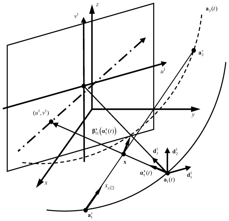
In the simulation, three rectangular planar detectors were used. Fig. 3 shows a rectangular planar detector corresponding to the source a1(t). The detector was so arranged that the line through the source and the detector center intersected the z-axis and detector perpendicularly. The parameters used in the simulation are listed in Table I. The filtered data are backprojected onto 512 inter-helix PI-lines for a fixed endpoint. There were 512 fixed endpoints for one reconstructed inter-helix PI-line surface, and 1536 reconstructed inter-helix PI-line surfaces in total. Both the 3-D Shepp–Logan phantom [37] and Defrise disk phantom [38] were used. These phantoms were respectively located at the center of the global coordinate system x-y-z within the same spherical support.
Fig. 3.
Detector plane and coordinate system for the triple-source FBP CBCT based on an inter-helix PI-line. x – y – z is the 3-D fixed-coordinate system, the 3-D rotated coordinate system for the source a1(t), the 1-D coordinate system for the inter-helix PI-line , and u1 – v1 the 2-D coordinate system on the corresponding detector plane of a1(t). The actual direction of the Hilbert filtering is along the cone-beam projection of on the detector plane, shown as the dashed–dotted line.
TABLE I.
Parameters Used in the Simulation
| Parameter | Value |
|---|---|
| Scanning radius | 75cm |
| Helix pitch | 18cm |
| Radius of spherical object support | 12.8cm |
| Distance from source to detector | 100cm |
| Scanning range | tj ∈ [−π,π] |
| Detector size | 51.2cm×12cm |
| Number of detector rows | 80 |
| Number of detector per row | 512 |
| Number of projections per turn | 1024 |
| Image grid | 256×256×256 |
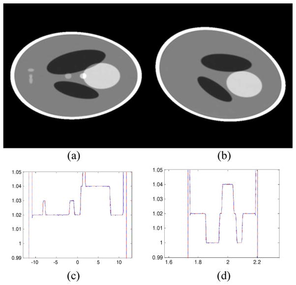
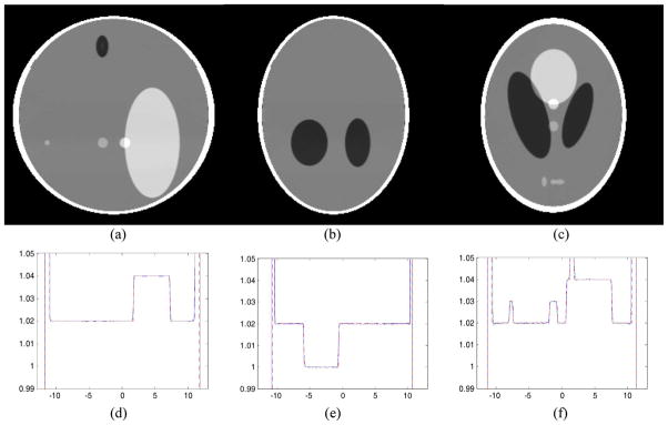
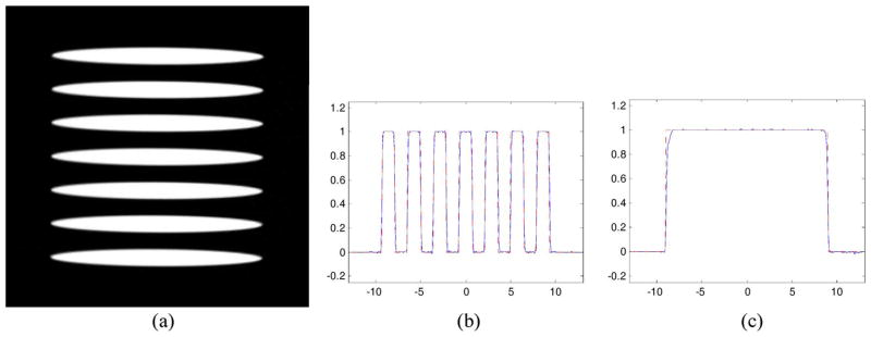
Fig. 4 presents the reconstructed images of the 3-D Shepp–Logan phantom in the inter-helix PI-line coordinates system. Fig. 5 gives the images reformatted into the Cartesian coordinate system. Fig. 6 shows the results for the Defrise phantom in the Cartesian coordinate system. All of the reconstructed images are in excellent agreement with the ideal phantom slices.
Fig. 4.
Representative reconstruction results with the Shepp–Logan phantom in the inter-helix PI-line based coordinate system. (a) and (b) Reconstructed slices in inter-helix PI-line based coordinates, where was fixed, and and formed the vertical and horizontal axes. Specifically, was varied from to , and was from −12.5 cm to 12.5 cm. The two images were reconstructed at and −0.3m5π, respectively. The display window is [0.99, 1.05]; (c) and (d) show the profiles along the lines in (a) and in (b), respectively.
Fig. 5.
Representative reconstruction results with the Shepp–Logan phantom in the Cartesian coordinate system. (a)–(c) The reconstructed slices of the 3-D Shepp–Logan phantom at x = 0 cm, y = 0 cm, and z = −3.2 cm, respectively. These results are obtained by interpolating the images in the inter-helix PI-line based coordinate system to Cartesian coordinates. The display window is [0.99, 1.05]. Typical profiles are shown along the lines specified by (d) x = 0 cm and z = 0 cm, (e) y = 0 cm and x = −3.2 cm, and (f) z = −3.2 cm and x = 0 cm.
Fig. 6.
Representative reconstruction results with the Defrise phantom in the Cartesian coordinate system. (a) A reconstructed image of the Defrise disk phantom at x = 0 cm with the display window [0, 1]. Typical profiles are shown along the lines specified by (b) x = 0 cm and y = 0 cm, and (c) x = 0 cm and z = 0 cm.
IV. Discussions and Conclusion
Although the symmetrical arrangement of triple sources is preferred, it is not a necessary condition for deriving the triple-source FBP formula (12). For a more general configuration
| (21) |
where j ∈ {1, 2, 3} and 0 ≤ φ1 < φ2 < φ3< 2π, the triple-source FBP formula (12) still holds exactly.
We can also extend the triple-source FBP formula (12) to perform exact reconstruction in the case of (2N + 1) sources, N ∈ ℕ. Let (2N + 1)-source helical loci be
| (22) |
where φj ∈ [0, 2π), φk < φk+1, j ∈ {1, 2,…, 2N + 1} and k ∈{1, 2,∈, 2N}.
First, let us extend the concept of the Zhao windows into the case of (2N + 1)-source helical CB scanning. For the source aj(t), the corresponding Zhao window is the region on the scanning cylinder bounded by the nearest helix turn of a(j+N−1)mod(2N+1)+1(t) and the nearest helix turn of a(j+N)mod(2N+1)+1(t), j ∈ {1, 2,…,2N + 1}. (The definition of Zhao window is given in the Appendix II). Then, we have the inter-helix PI-line for ai(t) and aj(t), i ≠ j, i ∈ {1, 2,…,2N + 1}, j ∈ {1, 2,…,2N + 1}, that intersects ai(t) at one point and aj(t) at another point with the absolute difference of the angular parameter values at both the intersection points less than 2π. The proofs of the existence and uniqueness properties of the inter-helix PI-lines are analogous to the proof of Theorem 2 in [12], [13]. Similarly, we have the backprojection operator for (2N + 1) sources
| (23) |
where j ∈ {1, 2,…, 2N+1}, and k ∈ {1, 2,…,2N+1}, N ∈ ℕ, and
| (24) |
Finally, let
| (25) |
then Theorem 3 can be extended to the following theorem for (2N + 1) sources.
Theorem 3
[(2N + 1)-source FBP reconstruction formula] Let Γj be a standard helix in ℝ3 parameterized by a function aj(t) (22), t ∈ ℝ, and j ∈ {1, 2,…, 2N + 1}, N ∈ ℕ. Then, the inversion formula
| (26) |
holds for all x ∈ Ω, provided that the mapping satisfies the normalization condition:
| (27) |
The normalization condition (27) holds for
| (28) |
for λj ∈ Ij and x · σ = aj(λj) · σ
Theorems 2 and 3 can also be extended to the cases of nonstandard helices in a similarly fashion.
Clearly, the more sources are used, the better the temporal resolution can be achieved, but the higher the system cost will be needed. How to place multiple sources and detectors under the physical constraints is a major issue in the system development, especially when more than two sources are used. Given the focus of this paper on the algorithm development, we would like only to point out that X-ray sources would be made more compact, more powerful and more cost-effective in the future to facilitate prototyping of multisource systems, and will not discuss the related technical issues further. While we have concentrated on the development of exact triple-source helical CBCT algorithms, we recognize that approximate CBCT algorithms should not be overlooked. As Tang et al. pointed out [44], [45], approximate CBCT algorithms have important merits in practical applications. In reference to the classic and recent findings on approximate CBCT [21]–[27], [39]–[45], the triple-source FBP algorithms presented in this paper may guide new development of approximate reconstruction algorithms for triple-source CBCT in both helical and circular scanning modes.
In conclusion, we have reported a triple-source FBP algorithm for helical CBCT. Our results allow exact and efficient image reconstruction with ultra-high temporal resolution. With adequate parallel computing hardware, our proposed triple-source FBP approach would run much faster than the BPF counterpart. Therefore, the triple-source FBP algorithm should be a good choice for practical helical CBCT. Our simulation results have verified our formulation, demonstrating excellent image quality. Finally, we have extended our work into the case of (2N + 1)-source helical CBCT to inspire or facilitate development of CT and micro-CT systems along this multi-source direction.
Acknowledgments
The authors would like to thank the anonymous reviewers for their comments and suggestions.
Appendix I
Inter-Helix PI-Lines and Inter-Helix PI-Arcs
The definition of inter-helix PI-lines for the triple-source case is as follows:
Definition
Let i, j ∈ {1, 2,3}, i ≠ j. aj(t) is defined by (21). The inter-helix PI-line between helices ai(t) and aj(t) can be defined as a line such that
The line intersects the two helices at aj(ti) and aj(tj), respectively;
The rotation angles ti and tj corresponding to the two intersections satisfy the following condition
| (29) |
For instance, if the three X-ray sources are symmetrically arranged, the three helices would be equally spaced. Thus the phases of the helices are
| (30) |
Then, for the inter-helix PI-line between a1(t) and a2(t), the rotation angles at the intersection points should satisfy
| (31) |
The inter-helix PI-lines for (2N + 1)-source can be defined in the same way.
As shown in Fig. 7, in the triple-source case there are three inter-helix PI-lines and for x ∈ Ω. The corresponding inter-helix PI-arcs are the coarse solid curve-segments and .
Appendix II
A) Definition of Zhao Window for Triple-Source
Define Zhao Window as the region of the scanning cylinder surface that is bounded by the helix turns {aj mod3+1(t) |(t−t0+2π/3) ∈ [−2π ⎣j/3⎦, 2π (1 − ⎣j/3⎦)]} and {a(j+1) mod3+1(t) |(t−t0 + 4π/3) ∈ [−2π ⎣j/2⎦, 2π (1 − ⎣j/2⎦)]}with aj(t0) as the vertex, j ∈ {1, 2, 3}. The symbol t0 is the angular parameter indicating the source position aj(t0).
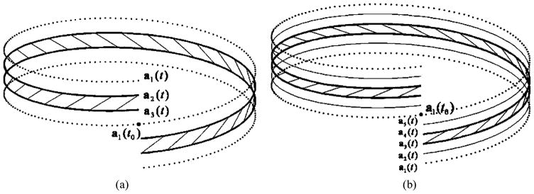
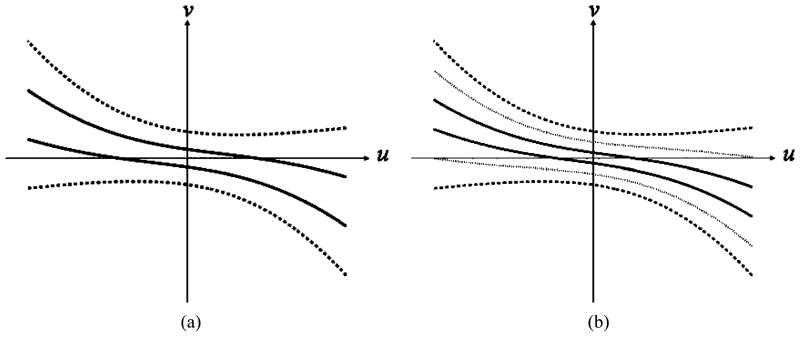
Fig. 8(a) shows the Zhao Window for the source position a1(t0) in the triple-source case. Fig. 9(a) shows the Zhao Window cone-beam projected onto the detector plane for triple-source. It is assumed that the detector plane is parallel to the axis of the spiral and is tangent to the spiral cylinder at the point opposite to the source.
Fig. 8.
Zhao Windows for the source position a1(t0) in the triple-source case (a) and quintuple-source case (b). The region bounded by the coarse solid curved lines is the Zhao Window.
Fig. 9.
Zhao Windows cone-beam projected onto the detector plane for triple-source (a) and quintuple-source (b). The region bounded by the dark solid lines is Zhao Window. The region bounded by the dark dashed lines is Tam-Danielsson Window. The light dotted lines are the other two helices. u–vis the coordinate system on the detector plane.
B) Definition of the Zhao Window for (2N + 1)-Source
Define Zhao Window as the region of the scanning cylinder surface that is bounded by the helix turns
and
with aj(t0)as the vertex, j ∈ {1,2, …, 2N + 1}. The symbol t0 is the angular parameter indicating the source position aj(t0).
Fig. 8(b) shows the Zhao Window for the source position a1(t0) in the quintuple-source case. Fig. 9(b) shows the Zhao Window cone-beam projected onto the detector plane for quintuple-source.
Appendix III
Scattering Reduction
One concern with triple-source CT is that the improvement in temporal resolution may be offset by the increment in scattering artifacts. In fact, there were similar arguments against the dual-source system in comparison with the single-source counterpart prior to the introduction of the Siemens Definition dual-source CT scanner. Actually, the Siemens dual-source CT scanner has received a very positive market response, which is encouraging for our proposed triple-source extension. Philosophically, we do not believe that the source and detector technology will not be advanced to accommodate the triple source system sooner or later.
The Siemens dual-source CT has been claimed to have a dose benefit because the second detector is smaller, and the dose is reduced at the edge of the field-of-view. The dual-source CT scanner can deliver double the power but it needs only half the dose for cardiac applications—without any compromise in image quality [51]. It has been reported that cross scatter is smaller with the decreased collimation z-width or the decreased object size for dual-source CT [52]. These guidelines should be valuable for optimization of triple-source CT.
Furthermore, we underline that the height of the Zhao window for triple-source CT is of only one third of the Tam-Danielsson window (please refer to Fig. 8(a) and Fig. 9(a) in Appendix II). Theoretically, the total dose delivered to the object remains the same as in the single-source case. For each source-detector pair of the triple source system, we have a significantly smaller collimation in z-width, and the cross scattering effect should be proportionally smaller. In practice, to decrease cross scattering and improve temporal resolution, low or mediate pitch triple-source CT scanning may well be an optimal balance.
Another potential strategy is to utilize shutters so that at any time instant the object is only exposed to one or two sources, since the shutters can be rapidly opened or closed in an alternative fashion [53]. Other scattering correction methods may also be used for the same purpose, such as the recently developed interior reconstruction techniques which have allowed exact reconstruction from purely local data assuming knowledge on a subregion in the volume of interest [50]. These promising techniques may be adapted for triple source CT to improve temporal resolution significantly at an acceptable radiation dose level.
Contributor Information
Jun Zhao, Email: junzhao@sjtu.edu.cn, Department of Biomedical Engineering, Shanghai Jiao Tong University, Shanghai, 200240, China.
Yannan Jin, Email: yannanjin@gmail.com, Department of Biomedical Engineering, Shanghai Jiao Tong University, Shanghai, 200240, China.
Yang Lu, Email: lvyang@sjtu.edu.cn, Department of Biomedical Engineering, Shanghai Jiao Tong University, Shanghai, 200240, China.
Ge Wang, Email: wangg@vt.edu, Biomedical Imaging Division, Virginia Tech/Wake Forest University (VT-WFU) School of Biomedical Engineering and Science, Virginia Tech, Blacksburg, VA 24061 USA.
References
- 1.Katsevich A. An improved exact filtered backprojection algorithm for spiral computed tomography. Adv Appl Math. 2004;32:681–697. [Google Scholar]
- 2.Zou Y, Pan X. Exact image reconstruction on PI-lines from minimum data in helical cone-beam CT. Phys Med Biol. 2004;49:941–959. doi: 10.1088/0031-9155/49/6/006. [DOI] [PubMed] [Google Scholar]
- 3.Katsevich A. A general scheme for constructing inversion algorithms for cone beam CT. Int J Math Math Sci. 2003;21:1305–1321. [Google Scholar]
- 4.Ye YB, Zhao SY, Yu HY, Wang G. Exact reconstruction for cone-beam scanning along nonstandard spirals and other curves. Proc. SPIE; Aug. 2004; pp. 293–300. [Google Scholar]
- 5.Ye Y, Zhao S, Yu H, Wang G. A general exact reconstruction for cone-beam CT via backprojection-filtration. IEEE Trans Med Imag. 2005 Sep;24(9):1190–1198. doi: 10.1109/TMI.2005.853626. [DOI] [PubMed] [Google Scholar]
- 6.Ye Y, Wang G. Filtered backprojection formula for exact image reconstruction from cone-beam data along a general scanning curve. Med Phys. 2005;30:42–48c. doi: 10.1118/1.1828673. [DOI] [PubMed] [Google Scholar]
- 7.Pack JD, Noo F, Clackdoyle R. Cone-beam reconstruction using the backprojection of locally filtered projections. IEEE Trans Med Imag. 2005;24(1):1–16. doi: 10.1109/tmi.2004.837794. [DOI] [PubMed] [Google Scholar]
- 8.Pack JD, Noo F. Cone-beam reconstruction using 1-D filtering along the projection of M-lines. Inverse Problems. 2005;21:1105–1120. [Google Scholar]
- 9.Chen G. An alternative derivation of Katsvich’s cone-beam reconstruction formula. Med Phys. 2003;30:3217–3226. doi: 10.1118/1.1628413. [DOI] [PubMed] [Google Scholar]
- 10.Zhao S, Yu H, Wang G. A family of analytic algorithms for cone-beam CT. Proc. SPIE; Aug. 2004; pp. 318–328. [Google Scholar]
- 11.Zhao S, Yu H, Wang G. A unified framework for exact cone-beam reconstruction formulas. Med Phys. 2005;32:1712–1721. doi: 10.1118/1.1869632. [DOI] [PubMed] [Google Scholar]
- 12.Zhao J, Jiang M, Zhuang T, Wang G. Minimum detection window and inter-helix PI-line with triple-source helical cone-beam scanning. Proc. SPIE; Aug. 2004; pp. 599–610. [Google Scholar]
- 13.Zhao J, Jiang M, Zhuang T, Wang G. Minimum detection window and inter-helix PI-line with triple-source helical cone-beam scanning. J X-Ray Sci Technol. 2006;14:95–107. [Google Scholar]
- 14.Zhao J, Jiang M, Zhuang TG, Wang G. Reconstruction algorithm for triple-source helical cone-beam CT. Proc. 27th Annu. Int. Conf. IEEE EMBS; Shanghai, China. Sep. 2005; pp. 1875–1878. [DOI] [PubMed] [Google Scholar]
- 15.Zhao J, Jiang M, Zhuang TG, Wang G. An exact reconstruction algorithm for triple-source helical cone-beam CT. J X-Ray Sci Technol. 2006;14:191–206. [Google Scholar]
- 16.Danielsson PE, Edholm P, Seger M. Toward exact 3-D-reconstruction for helical cone-beam scanning of long objects. A new detector arrangement and a new completeness condition. Int. Meeting Fully Three-Dimensional Image Reconstruction Radiol. Nucl. Med.; Pittsburgh, PA. 1997. pp. 141–144. [Google Scholar]
- 17.Tam KC, Samarasekera S, Sauer F. Exact cone beam CT with a spiral scan. Phys Med Biol. 1998;43:1015–1024. doi: 10.1088/0031-9155/43/4/028. [DOI] [PubMed] [Google Scholar]
- 18.Tuy HK. An inversion formula for cone-beam reconstruction. SIAM J Appl Math. 1983;43(3):546–552. [Google Scholar]
- 19.Pan X. Fast reconstruction with uniform noise properties in halfscan computed tomography. Med Phys. 2000;27:2031–2036. doi: 10.1118/1.1288239. [DOI] [PubMed] [Google Scholar]
- 20.Lee SW, Wang G. A Grangeat-type half-scan algorithm for cone-beam CT. Med Phys. 2003;30:689–700. doi: 10.1118/1.1562941. [DOI] [PubMed] [Google Scholar]
- 21.Liu Y, Liu H, Wang Y, Wang G. Half-scan cone-beam CT fluoroscopy with multiple x-ray sources. Med Phys. 2001;28:1466–1471. doi: 10.1118/1.1381549. [DOI] [PubMed] [Google Scholar]
- 22.Berninger BH, Redington RW. Multiple Purpose High Speed Tomographic X-Ray Scanner. 4 196 352. US Patent. 1980
- 23.Flohr TG, McCollough CH, Bruder H, Petersilka M, Gruber K, Suss C, Grasruck M, Stierstorfer K, Krauss B, Raupach R, Primak AN, Kuttner A, Achenbach S, Becker C, Kopp A, Ohnesorge BM. First performance evaluation of a dual-source CT (DSCT) system. Eur Radiol. 2006;16(2):256–68. doi: 10.1007/s00330-005-2919-2. [DOI] [PubMed] [Google Scholar]
- 24.Achenbach S, Ropers D, Kuettner A, Flohr T, Ohnesorge B, Bruder H, Theessen H, Karakaya M, Daniel WG, Bautz W, Kalender WA, Anders K. Contrast-enhanced coronary artery visualization by dual-source computed tomography–Initial experience. Eur J Radiol. 2006;57(3):331–5. doi: 10.1016/j.ejrad.2005.12.017. [DOI] [PubMed] [Google Scholar]
- 25.Johnson TR, Nikolaou K, Wintersperger BJ, Leber AW, von Ziegler F, Rist C, Buhmann S, Knez A, Reiser MF, Becker CR. Dual-source CT cardiac imaging: Initial experience. Eur Radiol. 2006;16(7):1409–15. doi: 10.1007/s00330-006-0298-y. [DOI] [PubMed] [Google Scholar]
- 26.Scheffel H, Alkadhi H, Plass A, Vachenauer R, Desbiolles L, Gaemperli O, Schepis T, Frauenfelder T, Schertler T, Husmann L, Grunenfelder J, Genoni M, Kaufmann PA, Marincek B, Leschka S. Accuracy of dual-source CT coronary angiography: First experience in a high pre-test probability population without heart rate control. Eur Radiol. 2006 Sep. doi: 10.1007/s00330-006-0474-0. to be published. [DOI] [PMC free article] [PubMed] [Google Scholar]
- 27.Kachelrieß M, Knaup M, Kalender WA. Multithreaded cardiac CT. Med Phys. 2006;33:2435–2447. doi: 10.1118/1.2207236. [DOI] [PubMed] [Google Scholar]
- 28.Palamodov VP. Reconstruction from ray integrals with sources on a curve. Inv Prob. 2004;4:239–242. [Google Scholar]
- 29.Orlov SS. Theory of three-dimensional reconstruction. I. Conditions for a complete set of projections. Sov Phys Crystallogr. 1975:511–515. [Google Scholar]
- 30.Ye Y, Yu H, Wei Y, Wang G. A general local reconstruction approach based on a truncated Hilbert transform. Int J Biomed Imag. 2007;2007:8. doi: 10.1155/2007/63634. [DOI] [PMC free article] [PubMed] [Google Scholar]
- 31.Zou Y, Pan X. An extended data function and its generalized backprojection for image reconstruction in helical cone-beam CT. Phys Med Biol. 2004;49:N383–387. doi: 10.1088/0031-9155/49/22/n02. [DOI] [PubMed] [Google Scholar]
- 32.Zou Y, Pan X. Image reconstruction on PI-lines by use of filtered backprojection in helical cone-beam CT. Phys Med Biol. 2004;49:2717–2731. doi: 10.1088/0031-9155/49/12/017. [DOI] [PubMed] [Google Scholar]
- 33.Sidky EY, Zou Y, Pan X. Minimum data image reconstruction algorithms with shift-invariant filtering for helical, cone-beam CT. Phys Med Biol. 2005;50:1643–1657. doi: 10.1088/0031-9155/50/8/002. [DOI] [PubMed] [Google Scholar]
- 34.Grangeat P. Mathematical framework of cone-beam 3-D reconstruction via the first derivative of the Radon transform. Lecture Note Math. 1992;1497:66–97. [Google Scholar]
- 35.Deng J, Yu H, Ni J, He T, Zhao S, Wang L, Wang G. A parallel Katsevich algorithm for 3-D CT image reconstruction. J Super-comput. 2006;38:35–47. [Google Scholar]
- 36.Yang J, Guo X, Kong Q, Zhou T, Jiang M. Parallel implementation of the Katsevish’s FBP algorithm. Int J Biomed Imag. 2006 doi: 10.1155/IJBI/2006/17463. [DOI] [PMC free article] [PubMed] [Google Scholar]
- 37.Zhao S, Wang G. Feldkamp-type cone-beam tomography in the wavelet framework. IEEE Trans Med Imag. 2000 Sep;19(9):922–929. doi: 10.1109/42.887839. [DOI] [PubMed] [Google Scholar]
- 38.Zhu J, Zhao S, Yu H, Ye Y, Lee SW, Wang G. Numerical studies on Feldkamp-type and Katsevich-type algorithms for cone-beam scanning along nonstandard spirals; Proc SPIE; Aug, 2004. pp. 558–565. [Google Scholar]
- 39.Feldkamp LA, Davis LC, Kress JW. Practical cone-beam algorithm. J Opt Soc Am. 1984;1(A):612–619. [Google Scholar]
- 40.Crawford CR, King KF. Computed-tomography scanning with simultaneous patient translation. Med Phys. 1990;17(6):967–982. doi: 10.1118/1.596464. [DOI] [PubMed] [Google Scholar]
- 41.Wang G, Lin TH, Cheng PC, Shinozaki DM. A general cone-beam reconstruction algorithm. IEEE Trans Med Imag. 1993 Sep;12(3):486–96. doi: 10.1109/42.241876. [DOI] [PubMed] [Google Scholar]
- 42.Yan M, Zhang C. Tilted plane Feldkamp type reconstruction algorithm for spiral cone beam CT. Med Phys. 2005;32:3455–3467. doi: 10.1118/1.2098154. [DOI] [PubMed] [Google Scholar]
- 43.Tang X, Hsieh J. A filtered backprojection algorithm for cone beam reconstruction using rotational filtering under helical source trajectory. Med Phys. 2004;31:2949–2960. doi: 10.1118/1.1803672. [DOI] [PubMed] [Google Scholar]
- 44.Tang X, Hsieh J, Hagiwara A, Nilsen RA, Thibault JB, Drapkin E. A three-dimensional weighted cone beam filtered backprojection (CB-FBP) algorithm for image reconstruction in volumetric CT under a circular source trajectory. Phys Med Biol. 2005;50:3889–3905. doi: 10.1088/0031-9155/50/16/016. [DOI] [PubMed] [Google Scholar]
- 45.Tang X, Hsieh J, Nilsen RA, Dutta S, Samsonov D, Hagiwara A. A three-dimensional-weighted cone beam filtered backprojection (CB-FBP) algorithm for image reconstruction in volumetric CT—Helical scanning. Phys Med Biol. 2006;51:855–874. doi: 10.1088/0031-9155/51/4/007. [DOI] [PubMed] [Google Scholar]
- 46.Zhang T, Chen GH. New families of exact fan-beam and cone-beam image reconstruction formulae via filtering the backprojection image of differentiated projection data along singly measured lines. Inverse Problems. 2006;22(3):991–1006. [Google Scholar]
- 47.Zou Y, Pan X, Sidky EY. Theory and algorithms for image reconstruction on chords and within regions of interest. J Optical Soc Amer A: Optics Image Sci, Vis. 2005;22(11):2372–2384. doi: 10.1364/josaa.22.002372. [DOI] [PubMed] [Google Scholar]
- 48.Bontus C, Köhler T, Proksa R. A quasiexact reconstruction algorithm for helical CT using a 3-Pi acquisition. Med Phys. 2003;30:2493–2502. doi: 10.1118/1.1601913. [DOI] [PubMed] [Google Scholar]
- 49.Köhler T, Bontus C, Koken P. The radon-split method for helical cone-beam CT and its application to nongated reconstruction. IEEE Trans Med Imag. 2006 Jul;25(7):882–897. doi: 10.1109/tmi.2006.876149. [DOI] [PubMed] [Google Scholar]
- 50.Ye Y, Yu H, Wang G. Exact interior reconstruction with cone-beam CT. Int J Biomed Imag. 2007;2007 doi: 10.1155/2007/10693. [DOI] [PMC free article] [PubMed] [Google Scholar]
- 51.Full cardiac detail at half the dose [Online]. Available: http://www.medical.siemens.com/webapp/wcs/stores/servlet/SMGenericDisplay~q_catalogId~e_-11~a_categoryId~e_1008408~a_cat-Tree~e_100010,1007660,12752,1008408~a_langId~e_-11~a_pageId~e_81802~a_storeId~e_10001.htm
- 52.Kyriakou Y, Kalender WA. Intensity distribution and impact of scatter on image quality for dual-source CT. Phys Med Biol. 2007;52(11):6969–6989. doi: 10.1088/0031-9155/52/23/014. [DOI] [PubMed] [Google Scholar]
- 53.Zhao J, Wang G. Scattering reduction for the multi-source CT via shutters. China Patent disclosure. submitted for publication. [Google Scholar]
- 54.Ye Y, Yu H, Wang G. Exact interior reconstruction from truncated limited-angle projection data. Int J Biomed Imag. 2008;2008 doi: 10.1155/2008/427989. [DOI] [PMC free article] [PubMed] [Google Scholar]
- 55.Lu Y, Zhao J, Wang G. Exact image reconstruction for triple-source cone-beam CT along saddle trajectories. Proc SPIE. 2008 Aug;7078 [Google Scholar]


