Abstract
A wireless sensor based on the magnetoelastic, magnetically soft ferromagnetic alloy was constructed for remote measurement of pressure in flowing fluids. The pressure sensor was a rectangular strip of ferromagnetic alloy Fe40Ni38Mo4B18 adhered on a solid polycarbonate substrate and protected by a thin polycarbonate film. Upon excitation of a time-varying magnetic field through an excitation coil, the magnetically soft sensor magnetized and produced higher-order harmonic fields, which were detected through a detection coil. Under varying pressures, the sensor's magnetoelastic property caused a change in its magnetization, altering the amplitudes of the higher-order harmonic fields. A theoretical model was developed to describe the effect of pressure on the sensor's higher order harmonic fields. Experimental observations showed the 2nd order harmonic field generated by the pressure sensor was correlated to the surrounding fluid pressure, consistent with the theoretical results. Furthermore, it was demonstrated that the sensor exhibited good repeatability and stability with minimal drift. Sensors with smaller dimensions were shown to have greater sensitivity but lower pressure range as compared to their larger counterparts. Since the sensor signal was also dependent on the location of the sensor with respect to the excitation/detection coil, a calibration algorithm was developed to eliminate signal variations due to the changing sensor location. Because of its wireless and passive nature, this sensor is useful for continuous and long-term monitoring of pressure at inaccessible areas. For example, sensors with these capabilities are suitable to be used in biomedical applications where permanent implantation and long-term monitoring are needed.
Keywords: Magnetic higher order harmonic fields, pressure sensors, magnetoelastic materials, wireless, embedded sensors
1. Introduction
In the last decade, wireless, passive sensors based on the magnetically soft, magnetoelastic materials have gained popularity for remote measurement of physical and biological/chemical parameters [1-3]. These sensors, known as the magnetoelastic sensors, are simple in design, in most cases nothing more than just a rectangular strip of magnetoelastic ferromagnetic alloy. Under an AC magnetic field excitation, these sensors physically vibrate due to their magnetic-soft and magnetoelastic properties, which efficiently convert magnetic field energy to mechanical vibration and vice versa. The vibration generates a secondary magnetic flux that can be independently detected, allowing remote sensing operations. Since the vibration amplitudes and frequencies of these sensors are proportional to the applied mass loading or pressure, they have been used for remote measurement of physical parameters such as air flux [4], flow velocity [5], pressure [6-8], temperature [9], liquid viscosity and density [10], and thin film elasticity [11]. By incorporating a chemical responsive, mass and/or elasticity changing coating on these sensors, they have also been used to detect humidity [9] and chemicals such as carbon dioxide [12], ammonia [13], and pH [14]. Similarly, incorporation of biological recognition elements such as antibodies to the sensors has allowed detection of biological agents such as Salmonella typhimurium [15], Escherichia coli [16], Pseudomonas aeruginosa [17], and penicillin [18]. Depending upon the application, magnetoelastic sensors can be remotely interrogated via magnetic, acoustic, or optical techniques [3]. The passive and wireless nature of magnetoelastic sensors, which allows the sensor to be embedded within a remote region, promotes long-term and continuous monitoring of parameters of interest. In addition, the low material cost allows these sensors to be used on a disposable basis.
Based on the similar material, we previously reported the development of the magneto-harmonic shift sensor for pressure monitoring [19-21]. The pressure sensor consisted of an airtight pressure chamber, where the magnetically soft material was attached to the bottom of the chamber. A permanent magnetic strip was also attached on the flexible membrane of the pressure chamber to generate a DC magnetic field. Under the excitation of a low frequency magnetic AC field, the magnetically soft material generated higher-order harmonic fields [22-23]. As the pressure changed, the separation distance between the two magnetic elements varied, changing the DC magnetic field experienced by the magnetically soft material. This altered the pattern of its higher-order harmonic fields, allowing it to be used for tracking pressure variations. A stress sensor was also fabricated based on the technology [24]. Instead of the pressure chamber, the stress sensor was made of a flexible substrate sandwiched by the two magnetic elements. An increase in stress compressed the substrate and decreased the separation distance between these two elements, thus changing the higher-order harmonic fields. Similarly, the same principle was applied for the construction of a liquid flow sensor [25]. For the magneto-harmonic shift sensors, higher-order harmonic signals were preferred over the fundamental mode signal due to the absence of the excitation field at the higher-order frequencies [22, 26-27], leading to larger signal-to-noise ratio and thus longer detection range. Compared to the magnetoelastic sensor, the magneto-harmonic shift sensors can monitor stresses and pressures of wider range (by changing the membrane or flexible substrate elasticity), but they are more complicated to design and fabricate.
A sensor based on the changes in the higher-order harmonic fields of a single magnetically soft, magnetoelastic strip was also reported for stress monitoring [22, 28]. Similar to the magneto-harmonic shift sensors, the sensor was detected by sending a low frequency magnetic field and measuring the higher-order magnetic fields. However, the single-strip harmonic sensor tracked stress by measuring the change in its higher-order harmonic amplitudes, which have been shown to be stress/pressure dependent [28]. Compared to the two-element magneto-harmonic shift sensor, the single-strip harmonic sensor is simple in design (just a rectangular strip of the material). Therefore, the single-strip sensor design has a significant reduction in the sensor dimension (≈80%, in terms of the thickness of the sensor), while maintaining the sensor response towards mechanical loading. The capability of sensor miniaturization is useful in applications that require the implantation of sensor within a structural without interrupting the setting of the structure. Miniature sensors are also particularly useful in biomedical applications where minimal surgery or less invasive techniques is preferred for embedding the sensor inside a human body.
In addition to the magneto-harmonic sensors, higher-order harmonic signals are also commonly used in quartz crystal microbalances (QCM), where the mechanical stiffness of a film was also characterized by the higher frequency components of the vibration spectrum [29]. Higher-order harmonics were also used for the purpose of obtaining enhanced analytical signals [30] and to enhance the sensitivity of QCM [31]. It was reported that when the QCM was vibrated at the 7th order of the fundamental frequency, the sensitivity of the device was improved by eighth folds [31]. However, difficulties in exciting QCM at frequencies beyond the 7th order were encountered due to the low piezoelectric coupling [32]. It was also reported by Thompson and coworkers that at higher-order harmonics, the amplitude of the signal was significantly reduced and eventually diminished [32].
In this work, we report the application of the single-strip magneto-harmonic sensor for fluid pressure monitoring. This study included the fabrication of the sensor, as well as investigations of the sensor sensitivity as a function of sensor dimensions. Experiment results showed the amplitude of the 2nd-order harmonic field increased with increasing fluid pressure. A theoretical model was also developed to explain the behavior of the sensor with changing fluid pressure. Furthermore, a calibration algorithm was developed to remove the effect of changing the sensor location from the measurements.
2. Theoretical Model
Due to the non-linearity and low hysteresis loss in the magnetization process [22, 33], a magnetically soft material can also produce magnetic fluxes at frequencies higher than the frequency of the excitation field. These high frequency fields, the higher-order harmonic fields, also dependent on the strength of a DC biasing field [22, 33]. Therefore, to detect the higher-order harmonic fields, a varying DC biasing field is commonly applied in addition to the AC excitation field to measure the harmonic field amplitude as a function of the DC biasing field. For sensor applications, the characteristics of the harmonic-field versus DC-field plot, such as its shape or magnitude, can be used to track the parameter of interest.
The pressure sensitivity of the magnetically soft, magnetoelastic material can be explained by the stress dependency of its anisotropy field, Hk. As reported, the anisotropy field of a magnetic material, which is the field needed to saturate the magnetization, can be related to the tensile stress along the magnetization direction as [34]:
| (1) |
where Hk0 is the anisotropy field at zero stress, Ms is the saturation magnetization flux, λs is the saturation magnetostriction of the material, and σx is the tensile stress along the magnetization direction, which is also along the length of the sensor.
Eq. (1) describes the change in anisotropy field due to the tensile stress along the sensor's length. However, in practice, the stress along the sensor's length caused by the liquid pressure is insignificant compared to the compression stress at the transverse direction (at the dominant surface of the sensor). Therefore, the transverse stress on the sensor surface is related to the tensile stress along the sensor length using the Poisson's ratio υ as:
| (2) |
Note that a scaling factor of two is added in Eq. (2) to compensate for the fact that only one side of the sensor is facing the pressure from the liquid.
As shown in Eq. (1), increasing stress (σx) decreases the anisotropy field of a magnetic material, assuming the anisotropy energy and the saturation magnetization stay constant. The change in anisotropic field has a direct impact on the amplitude of the n-th order magnetic harmonic field An, which can be described by the equation [22]:
| (3) |
where L is a variable that accounts for sensor-coil coupling, Bs is the saturation induction flux (for ferromagnetic materials, Bs ≈ Ms), ω is the radian frequency of the fundamental order, hac is the AC excitation field, and Hdc is the DC biasing field. Under an externally applied pressure, the sensor material deforms and generates an internal stress. Based on Eq. (1) – (3), the stress will cause a change in the higher-order magnetic fields, allowing remote detection of pressure.
3. Experimental
3.1. Sensor Fabrication
Two rectangular strips of pressure-sensitive magnetoelastic material were sheared from a roll of Metglas 2826MB alloy (Fe40Ni38Mo4B18) into 35 mm × 5 mm × 26 μm (Sensor A) and 35 mm × 8 mm × 26 μm (Sensor B). Sensor A and B were separately adhered on polycarbonate substrates (50 mm × 10 mm × 3 mm). The other sides of the sensors were covered with polycarbonate films with thickness of 130 μm. The construction of the sensor is illustrated in Fig. 1.
Fig. 1.
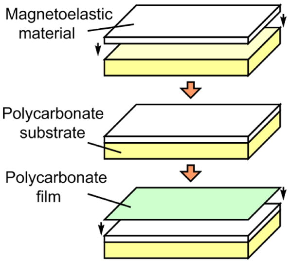
The construction of a pressure sensor based on the magnetoelastic/magnetostrictive material. The pressure sensor had a sandwich configuration which consisted of a polycarbonate substrate, a magnetoelastic material, and a polycarbonate protective film.
3.2. Experimental Setup and Procedures
Fig. 2 illustrates the test setup used to evaluate and characterize the performance of the pressure sensor. The pressure sensor was embedded within a conduit and was placed in close proximity with the excitation and detection coils. The fluid flow was controlled by a flow regulator and the actual pressure was measured with a commercial pressure meter (MediaSensor™, SSI Technologies, Inc.). The interrogation electronic instruments, which include a spectrum analyzer, a function generator, a DC power supply, an amplifier, and a personal computer, was used to communicate and control the excitation and detection coils. The excitation coil, measuring 25 cm in diameter, consisted of 2 superimposed AC and DC excitation coils, made of 63 turns of 18-gauge laminated copper wire. The AC excitation coil was connected to an AC function generator (Fluke 271 10MHz) and an amplifier (Tapco J1400), while the DC excitation coil was connected to a DC power supply (Kepco MBT 36-10M).
Fig. 2.
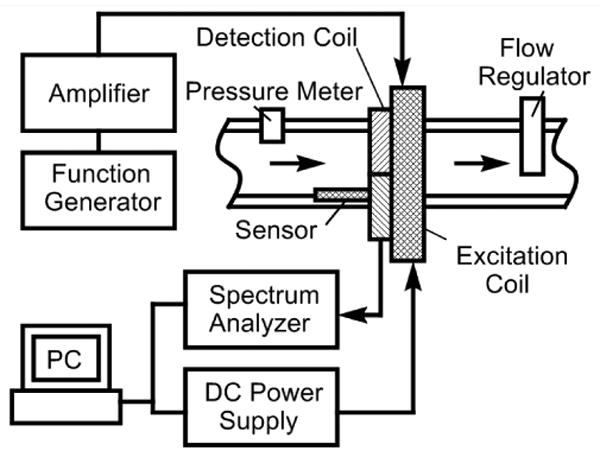
A diagram illustrates the experimental design for wireless and passive pressure monitoring.
The pressure sensors were remotely excited with a 200 Hz sinusoidal signal produced by the function generator. The pressure sensors were exposed to fluid pressures from 0 to 62 kPa. At each increment of pressure, the 2nd higher-order magnetic fields produced by the sensors, at 400 Hz, were remotely captured by the network/spectrum analyzer through the detection coil while varying the DC biasing fields, producing the harmonic field versus DC biasing field plots. The 2nd order harmonic fields were monitored instead of other harmonic fields because they had the larger field amplitude, thus lowest signal-to-noise ratio. The maximum 2nd order harmonic field amplitude was determined as the highest peak (amplitude) in the harmonic field versus DC biasing field plots. The maximum 2nd order harmonic fields were correlated to the reading collected from the commercial pressure meter.
4. Results and Discussion
4.1. Theoretical Results
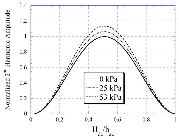
Using Eq. (1)-(3), the changes in the maximum 2nd order harmonic fields of the sensor were calculated as a function of stress. The anisotropy field at zero stress, Hk0, was set as 150 A/m [22], and the saturation magnetostriction and induction were 12 ppm and 0.88 Tesla, respectively [35]. Fig. 3 shows the amplitude of the 2nd order harmonic spectrum, plotted against the ratio of the DC biasing field to the AC excitation field, at varying stresses. To compare the harmonic fields of the sensor under varying stress, the DC offset of the plots, an artifact of the theoretical model that used Fourier series expansion to model the BH curve of the sensor, was removed. In addition, all curves were normalized to the maximum 2nd order harmonic amplitude at zero stress. As shown in the figure, the maximum amplitudes of the sensor increased with increasing stress. This was due to the decrease in the anisotropy field at larger pressure, which led to larger signal amplitudes.
Fig. 3.
Theoretical results showing the 2nd order harmonic field of the sensor decreased with increasing stress.
4.2. Experimental Observations
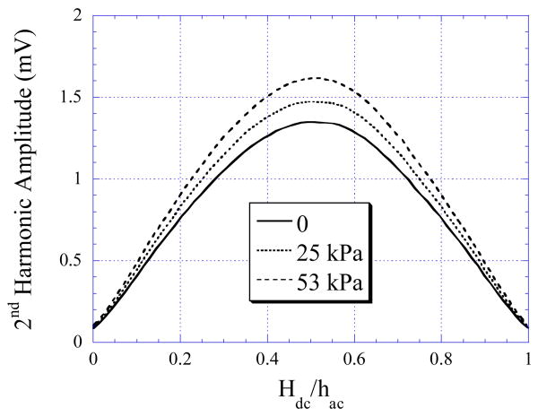
The relationship between the higher-order harmonic amplitude and the fluid pressure was evaluated by incorporating the pressure sensor into the flowing system with a flow rate of 157 cm3/s and pressure varying from 0 to 62 kPa. The 2nd order harmonic fields produced by the pressure sensor were remotely captured and plotted in Fig. 4. As shown in the figure, the maximum 2nd order harmonic amplitude exhibited by the sensors increased with respect to the increasing fluid pressure. This outcome was consistent with the theoretical model.
Fig. 4.
Measured 2nd order harmonic fields of the sensor versus DC biasing field at varying stress.
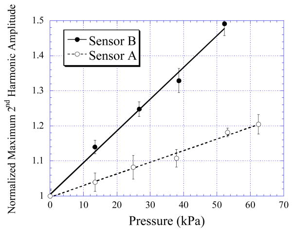
Fig. 5 plots the changes in the 2nd order harmonic amplitude when sensors of different sizes were exposed to 20 cycles of varying pressures. The figure demonstrates that Sensor B, with smaller size, exhibited greater pressure sensitivity. This was because the smaller sensor has a smaller surface area. Therefore, although the force loading from the liquid pressure was the same for both sensors, the smaller sensor actually received more stress as stress was defined as force over surface area. Depending on the application and type of usage, the sensitivity and detection range of the sensor can be controlled by varying the size of the magnetoelastic material.
Fig. 5.
The normalized 2nd order harmonic amplitudes exhibited by Sensor A (35 mm × 5 mm) and Sensor B (35 mm × 8 mm) under varying fluid pressures.
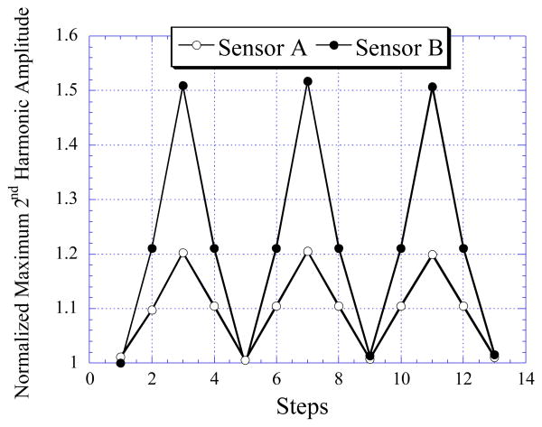
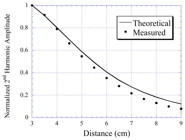
The repeatability exhibited by Sensor A and B was demonstrated by applying several cycles of pressure variations to the sensors. As shown in Fig. 6, both the sensors exhibited good repeatability and stability with minimal drift occurred after the first cycle of loading. Fig. 7 shows the 2nd order harmonic field generated by Sensor A decreased as the distance between the center of the excitation coil and the center of the sensor increased. The relative decrease in magnetic field due to the separation distance between the sensor and the coil was modeled with an equation derived from the Biot-Savart law [36]:
Fig. 6.
The repeatability and stability exhibited by Sensor A (35 mm × 5 mm) and B (35 mm × 8 mm) under several cycles of loading between 0 to 62 kPa.
Fig. 7.
The normalized measured and theoretically calculated 2nd order harmonic fields of Sensor A as a function of the distance between the sensor and excitation coil.
| (4) |
where Bmax is the magnetic field generated when the sensor was 3 cm from the coil (the sensor signal was maximal at this location), re and rd are the radii of the excitation and detection coils, respectively, xm is the distance where Bmax was recorded (3 cm), and x is distance from the sensor to the excitation coil. The theoretical change in the normalized 2nd order harmonic amplitude, B(x)/Bmax, was calculated with Eq. (4) and plotted in Fig. 7. As shown in the figure, the change in the 2nd order harmonic amplitude was accurately described with Eq. (4).
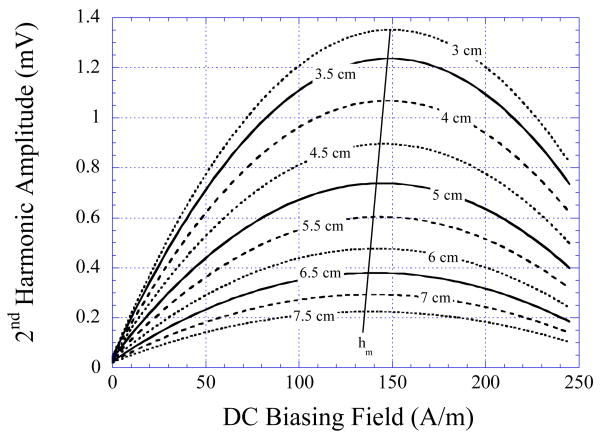
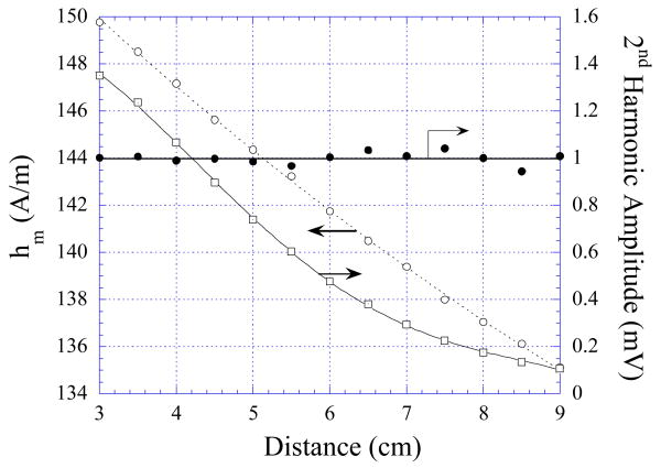
Due to the position-sensitive nature of this sensor technology, all measurements must be calibrated prior to obtaining useful measurements. It was observed that in addition to the change in signal amplitude, the sensor location also affect the DC biasing field where the sensor exhibited maximum signal (hm). As illustrated in Fig. 8, hm of Sensor A showed an almost linear decrease as the sensor was further away from the detection/excitation coil. Since hm was independent from the pressure but sensitive to location, its variation was used to determine the location of the sensor to calibrate for the pressure measurements.
Fig. 8.
The 2nd order harmonic field of the sensor at zero stress decreased with the sensor was further from the excitation coil. The numbers in the plot indicates the center-to-center distance between the sensor and the excitation coil.
Fig. 9 shows the change in the 2nd order harmonic amplitude, Am, and hm of Sensor A. The data of Am was curve-fitted with a 3rd order polynomial curve and the data of hm was curve-fitted with a 2nd order polynomial curve. A calibration routine was developed based on these two curves. First, the calibration routine calculated the location of the sensor by entering the measured hm into the 2nd order polynomial curve and solving for the 2nd order polynomial equation. Upon determining the calculated location, the routine calculated the expected 2nd order harmonic amplitude of the sensor using the 3rd order polynomial curve. The accuracy of the calibration routine was determined by normalizing the expected 2nd order harmonic amplitude to the actual 2nd order harmonic amplitude measurement (see the Measured/Calculated curve in Fig. 9). As shown in Fig. 9, the calibration routine was very accurate when the distance of the sensor was 6 cm away from the coils (<1% error). However, as the distance increased, the accuracy decreased due to the increase in the measurement noise compared to the actual sensor signal.
Fig. 9.
The change in Am (maximum 2nd order harmonic field amplitude) and hm (DC biasing field that corresponded to the maximum 2nd harmonic amplitude) of Sensor A was curve-fitted with the 3rd order and 2nd order polynomial curves, respectively. The ratio of the measured to calculate signal amplitude is also plotted.
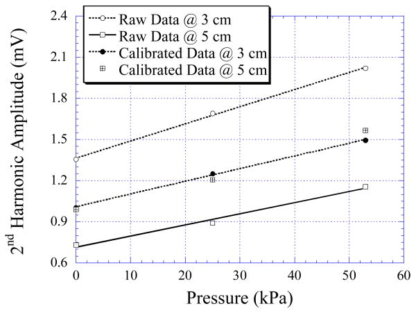
Fig. 10 plots the 2nd order harmonic field amplitude of the sensor as a function of fluid pressure when the sensor was placed at two different locations (3 cm and 5 cm from the coils). As shown in the figure, the raw measurements were dependent on both pressure and location, which prevented the sensor from providing the actual pressure measurement. The raw measurement data were calibrated using the above mentioned method, and the results are plotted in Fig. 10. As shown, the calibration routine has significantly removed the location dependency of the sensor.
Fig. 10.
The maximum 2nd order harmonic field amplitude of Sensor A when it was 3 cm (Raw Data @ 3 cm) and 5 cm (Raw Data @ 5 cm) from the detection coil. The calibrated data at both positions are also plotted.
Conclusion
The fabrication and application of a wireless, passive sensor for monitoring pressure in flowing fluid was demonstrated. Experimental results indicated that the single-strip magneto-harmonic pressure sensor exhibited linear correlation with respect to the fluid pressure. Also, it was shown that the sensor exhibited minimal drift and hysteresis. Since the sensor signal was also sensitive to the location of the sensor with respect to the detection and excitation coils, a calibration method was developed to eliminate the location effect.
The sensors presented in this paper were tested at pressure range from 0 to 62 kPa. The results showed that sensor could be used for in vivo monitoring of blood pressure, such as in an aneurysm sac (0 to 27 kPa) [37]. Other potential applications for sensors with this range include aortic pressure measurement, with pressure range from 10 – 18 kPa for physiological conditions and up to 40 kPa for unphysiological conditions [38], or left ventricular pressure measurement, with 0 - 16 kPa for physiological conditions and up to 40 kPa for unphysiological conditions [38]. These sensors could also be used for intrauterine pressure measurement (0-10 kPa for physiological conditions and 0 to 25 kPa for unphysiological conditions) [38].
The implantable sensor, which could allow long-term and continuous monitoring of blood pressure, is favorable for chronic patients as it will allow point-of-care diagnostics, improve the detection efficacy, and lower the overall medical cost. As compared to the two-element magneto-harmonic sensors, the described sensor will be smaller and easier to be miniaturized due to its simpler design. Future works include the miniaturization of sensor, optimization of the excitation and detection coils, as well as construction of a completely portable system and improving the sensor compatibility to the biological system.
Acknowledgments
The project described was supported by Grant Number R15EB008883 from the National Institute of Biomedical Imaging and Bioengineering. The content is solely the responsibility of the authors and does not necessarily represent the official views of the National Institute of Biomedical Imaging and Bioengineering or the National Institutes of Health.
References
- 1.Ong KG, Zeng K, Yang X, Shankar K, Ruan C, Grimes CA. Quantification of multiple bioagents with wireless, remote-query magnetoelastic micro-sensors. IEEE Sensors Journal. 2006 June;6(no. 3):514–523. [Google Scholar]
- 2.Ong KG, Leland JM, Zeng K, Barrett G, Zourob M, Grimes CA. A rapid highly-sensitive endotoxin detection system. Biosensors and Bioelectronics. 2006 June;21:2270–2274. doi: 10.1016/j.bios.2005.11.007. [DOI] [PubMed] [Google Scholar]
- 3.Grimes CA, Mungle CS, Zeng K, Jain MK, Dreschel WR, Paulose M, Ong KG. Wireless magnetoelastic resonance sensors: a critical review. Sensors. 2002 July;2:294–313. [Google Scholar]
- 4.Coneño AF, Zhukov A, Blanco JM, González J. Air-flux magnetoelastic sensor based on inverse Wiedemann effect of amorphous ribbon. Sensors and Actuators A. 2003 Sept;106:174–178. [Google Scholar]
- 5.Kouzoudis D, Grimes CA. Remote query fluid-flow velocity measurement using magnetoelastic thick film sensors. J Appl Phys. 2000 May;87(no. 9):6301–6303. doi: 10.1016/s0924-4247(00)00306-x. [DOI] [PubMed] [Google Scholar]
- 6.Kouzoudis D, Grimes CA. The frequency response of magnetoelastic sensors to stress and atmospheric pressure. Smart Mater Struct. 2000 May;9:885–889. [Google Scholar]
- 7.Grimes CA, Stoyanov PG, Kouzoudis D, Ong KG. Remote query pressure measurement using magnetoelastic sensors. Rev Sci Instrum. 1999 Dec;70(no. 12):4711–4714. [Google Scholar]
- 8.Grimes CA, Kouzoudis D. Remote query measurement of pressure, fluid-flow velocity, and humidity using magnetoelastic thick-film sensors. Sens Actuators. 2000 Sept;84:205–212. doi: 10.1016/s0924-4247(00)00306-x. [DOI] [PubMed] [Google Scholar]
- 9.Jain MK, Schimdt S, Ong KG, Mungle C, Grimes CA. Magnetoacoustic remote query temperature and humidity sensors. Smart Mater Struct. 2000 June;9:502–510. [Google Scholar]
- 10.Jain MK, Schmidt S, Grimes CA. Magneto-acoustic sensors for measurement of liquid temperature, viscosity, and density. Appl Acoustic. 2001 Aug;62(no. 8):1001–1011. [Google Scholar]
- 11.Ong KG, Jain MK, Mungle C, Schmidt S, Grimes CA. Magnetism-based sensors. Proceedings of SPIE; San Diego. 2001. pp. 158–172. [Google Scholar]
- 12.Cai QY, Cammers-Goodwin A, Grimes CA. A wireless remote query magnetoelastic CO2 sensor. J Environ Monit. 2000 Sept;2:556–560. doi: 10.1039/b004929h. [DOI] [PubMed] [Google Scholar]
- 13.Cai QY, Jain MK, Grimes CA. A wireless, remote query ammonia sensor. Sens Actuators B. 2001 March;77:614–619. doi: 10.1016/s0925-4005(01)00766-3. [DOI] [PubMed] [Google Scholar]
- 14.Cai QY, Grimes CA. A remote query magnetoelastic pH sensor. Sens Actuators B. 2000 Nov;71:112–117. doi: 10.1016/s0925-4005(00)00599-2. [DOI] [PubMed] [Google Scholar]
- 15.Guntupalli R, Lakshmanan RS, Johnson ML, Hu J, Huang TS, Barbaree JM, Vodyanoy VJ, Chin BA. Magnetoelastic biosensor for the detection of Salmonella typhimurium in food products. Sens And Instrumen Food Qual. 2007 March;1(no. 1):3–10. [Google Scholar]
- 16.Ruan C, Zeng K, Varghese OK, Grimes CA. Magnetoelastic immunosensors: amplified mass immunosorbent assay for detection of Escherichia coli O157:H7. Anal Chem. 2003 Oct;75:6494–6498. doi: 10.1021/ac034562n. [DOI] [PubMed] [Google Scholar]
- 17.Pang P, Huang S, Cai Q, Yao S, Zeng K, Grimes CA. Detection of Pseudomonas aeruginosa using a wireless magnetoelastic sensing device. Biosensors and Bioelectronics. 2007 Sept;23:295–299. doi: 10.1016/j.bios.2007.07.004. [DOI] [PubMed] [Google Scholar]
- 18.Gao X, Zhen R, Zhang Y, Grimes CA. Detecting penicillin in milk with a wireless magnetoelastic biosensor. Sensor Letters. 2009 Feb;7(no. 1):6–10. [Google Scholar]
- 19.Tan EL, Pereles BD, Horton BE, Shao R, Zourob M, Ong KG. Implantable biosensors for real-time strain and pressure monitoring. Sensors Journal. 2008 Oct;8(no. 10):6396–6406. doi: 10.3390/s8106396. [DOI] [PMC free article] [PubMed] [Google Scholar]
- 20.Tan EL, Pereles BD, Ong KG. A wireless and passive implantable pressure sensor. Sensor Letters. 2009 Feb;7:1–7. doi: 10.3390/bios1040134. [DOI] [PMC free article] [PubMed] [Google Scholar]
- 21.Pereles BD, Tan EL, Ong KG. A remote query pressure sensor based on magnetic higher-order harmonic fields. IEEE Sensors Journal. 2008 Nov;8:1824–1829. doi: 10.1109/jsen.2010.2041223. [DOI] [PMC free article] [PubMed] [Google Scholar]
- 22.Ong KG, Grimes CA. Tracking the harmonic response of magnetically-soft sensors for wireless temperature, stress, and corrosive monitoring. Sensors and Actuators A. 2002 April;101:49–61. doi: 10.1016/s0924-4247(02)00180-2. [DOI] [PubMed] [Google Scholar]
- 23.Fletcher RR, Gershenfeld NA. Remote interrogated temperature sensors based on magnetic materials. IEEE Trans Magn. 2000 Sept;36(no. 5):2794–2795. [Google Scholar]
- 24.Tan EL, Pereles BD, Ong J, Ong KG. A wireless, passive strain sensor based on the harmonic response of magnetically-soft materials. Smart Materials and Structures. 2008 Feb;17:1–7. [Google Scholar]
- 25.Pereles BD, Shao R, Tan EL, Ong KG. A wireless flow sensor based on magnetic higher-order harmonic fields. Smart Materials and Structures. 2009 July;18:1–6. [Google Scholar]
- 26.Ripka P. Review of fluxgate sensors. Sensors and Actuators A. 1992;33:129–141. [Google Scholar]
- 27.Cruz JC, Trujillo H, Rivero M. New kind of fluxgate magnetometer probe with enhanced electronic processing. Sensors and Actuators A. 1998 Dec;71:167–171. [Google Scholar]
- 28.Ong KG, Grimes CA. Magnetically soft higher order harmonic stress and temperature sensors. IEEE Transactions on Magnetics. 2003 Sept;39(no. 5):3414–3416. [Google Scholar]
- 29.Johannsmann D. Derivation of the shear compliance of thin films on quartz resonators from comparison of the frequency shifts on different harmonics: a perturbation analysis. Journal of Applied Physics. 2001 June;89:6356–6364. [Google Scholar]
- 30.Thompson M, Ballantyne SM, Cheran L, Stevenson AC, Lowe CR. Electromagnetic excitation of high frequency acoustic waves and detection in the liquid phase. Analyst. 2003 July;128:1048–1055. [Google Scholar]
- 31.Okahata Y, Matsuura K, Ebara Y. Gas-phase molecular recognition on functional monolayers immobilized on a highly sensitive quartz-crystal microbalance. Supramolecular Science. 1996 May;3:165–169. [Google Scholar]
- 32.Ballantyne SM, Thompson M. Superior analytical sensitivity of electromagnetic excitation compared to contact electrode instigation of transverse acoustic waves. Analyst. 2004 February;129:219–224. doi: 10.1039/b313314c. [DOI] [PubMed] [Google Scholar]
- 33.Ong KG, Grimes DM, Grimes CA. Higher-order harmonics of a magnetically-soft sensor: Application to remote query temperature measurement. Applied Physic Letters. 2002 May;80(no. 20):3856–3858. [Google Scholar]
- 34.Livingston JD. Magnetomechanical property of amorphous metals. Phys Status Solid A. 2006 Feb;70:591–596. [Google Scholar]
- 35.Ong KG, Mungle CS, Grimes CA. Control of a magnetoelastic sensor temperature response by magnetic field tuning. IEEE Transactions on Magnetics. 2003 April;39:3414–3416. [Google Scholar]
- 36.Ulaby FT. Fundamentals of Applied Electromagnetics. ch. 5 Pearson Prentice Hall; 2006. [Google Scholar]
- 37.Ellozy SH, Carrocio AC, Lookstein RA, Minor ME, Sheahan CM, Juta J, Cha A, Valenzuela R, Addis MD, Jacobs TS, Teodorescu VJ, Marin ML. First experience in human beings with a permanently implantable intrasac pressure transducer for monitoring endovascular repair of abdominal aortic aneurysms. Journal of Vascular Surgery. 2004 September;40:405–412. doi: 10.1016/j.jvs.2004.06.027. [DOI] [PubMed] [Google Scholar]
- 38.Togawa T, Tamura T, Oberg PA. Biomedical Transducers and Instruments. CRC Press; New York: 1997. p. 14. [Google Scholar]


