Abstract
This article presents a model-based compensator for canceling friction in the tendon-driven joints of a haptic-feedback teleoperator. Unlike position-tracking systems, a teleoperator involves an unknown environment force that prevents the use of tracking position error as a feedback to the compensator. Thus, we use a model-based feedforward friction compensator to cancel the friction forces. We provide conditions for selecting compensator parameters to ensure passivity of the teleoperator and demonstrate performance experimentally.
Index Terms: haptic feedback, telerobotics, friction compensation, transparency, passivity
I. Introduction
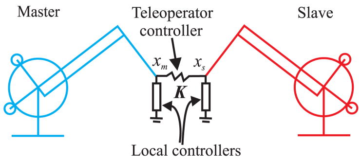
The dynamic properties of the manipulators of a haptic-feedback teleoperator (Figure 1) limit the transparency of a teleoperator in transferring forces of the environment to the operator. When an operator moves the master manipulator to direct the slave manipulator, forces of the manipulators due to inertia and friction resist the operator’s motion. These forces contribute to the operator’s fatigue and mask small forces between the slave manipulator and the environment.
Fig. 1.
A teleoperator consists of a master manipulator, a slave manipulator, and a controller that virtually connects the tips of the two manipulators. Local controllers are added to compensate for friction of the manipulators.
Ideally, force sensors can be used to eliminate resistant forces of the manipulators from being fed back to the human operator [1], but because of the practical limitations of applying force sensors in robot-assisted surgery (due to geometry, size, biocompatibility, sterilization, and cost), we seek to develop haptic feedback methods that do not require force sensors. Thus, we use a position-tracking controller to provide haptic feedback and a feedforward strategy to cancel the resistant forces. The tracking controller commands the master manipulator to follow the slave manipulator. The controller applies a force to the operator when the master manipulator is displaced from its desired position.
Unlike position-tracking systems, teleoperator systems include an unknown environment force. We show that the unknown environment force prevents the use of tracking position error as a feedback to the friction compensator. We illustrate how non-model-based controllers [2], [3], [4] and observer-based compensators [5], [6], [7] used to reduce tracking errors of position tracking systems are not applicable to friction compensation for a teleoperator. Then, we use model-based compensators to cancel friction forces of the teleoperator.
Stability is an essential requirement for a haptic-feedback teleoperator. Model-based friction compensation increases the transparency of a teleoperator but can destabilize it. To ensure the stability of the teleoperator, where the user and environment forces are unknown, the friction compensation terms should be selected such that the passivity of the teleoperator is preserved.
For a teleoperator with tendon-driven joins, friction occurs at several stages of power transmission. It occurs in the actuator that moves the tendon, the joint of the manipulator driven by the tendon, and the pulleys that support the tendon. Since the tendon is stretched during force transmission, the displacements of the friction surfaces of the tendon mechanism are different from the displacement input to the controller. These displacement lags are much larger than the presliding distances of the friction surfaces of the transmission and should be considered in the design of compensators to ensure passivity of the teleoperator.
Model-based friction compensation has been used for haptic displays [8], [9], tendon-driven joints [10], [11], [12], and elastic joints [13], but the required conditions to ensure passivity of the joint after friction compensation were not addressed. A Dahl-based friction compensator [14] has been recently used for compensating friction in tendon-driven joints [11], [15], [16] and tendon-sheath transmission systems [17] to prevent oscillations. However, the Dahl friction model exhibits plastic behavior in presliding motion [18], which makes it difficult to guarantee the passivity of the joint [16]. In this work, we use single-state elastic friction models to compensate the friction in a tendon-driven joint and provide conditions for selecting compensator parameters to ensure passivity of the joint. Single-state elastic models are more applicable than dynamic friction models [18] for friction compensation of tendon-driven manipulators where transmissions are considerably more compliant than asperities at the joint surfaces [16].
II. Effect of Friction on Transparency of a teleoperator
We now analyze the effect of friction on transparency of a haptic-feedback position-tracking teleoperator, and discuss the challenges involved in model-based friction compensation for enhancing transparency.
A. Transparency for a Teleoperator with Friction
In general, the requirements for a transparent teleoperator are [19]:
Force tracking: The master manipulator should apply the forces of the teleoperated environment to the operator.
Position tracking: The slave manipulator should follow the position of the master manipulator.
The transparency of a teleoperator is typically analyzed by modeling a teleoperator as a two port linear network [20], [21]. The transparency is then quantified in terms of a match between the impedance of the environment and the impedance transmitted to the operator [21]. Due to nonlinearity of friction, we study the effect of friction on position and force tracking performance of a teleoperator based on the state-space equations of the teleoperator.
B. State Equations of a Position-Tracking Teleoperator
The Cartesian state equations of the master and slave manipulators are written as:
| (1) |
where xm and xs are the position-orientation vectors of the end-effectors of the manipulators, Mm and Ms are Cartesian mass matrices, Cm and Cs are Coriolis and centrifugal matrices, fm,f and fs,f are friction force-torque vectors, fu is the user force-torque vector, fe is the environment force-torque vector, and fm,c and fs,c are controller force-torque vectors. The subscripts m and s refer to the master and slave, respectively. Mm, Ms, Cm, Cs may depend on the positions and velocities of the joints of the manipulators. Gravity terms could also be considered in (1), but they do not change the analysis of the effect of friction on transparency.
The control structure we use includes two proportional position- tracking controllers, and two local feedforward controllers fm,l, and fs,l:
| (2) |
where K is a diagonal matrix that contains six proportional gains. The proportional controllers are effectively a a virtual network of springs that connect the tips of the two manipulators. The local controllers compensate for friction of the manipulators.
C. Friction Effect on Force Tracking
The relation between the environment force and the operator force is obtained by combining (1) and (2) and canceling out the proportional controllers:
| (3) |
The force displayed to the operator is the sum of environment force, friction forces, local controller forces, inertial forces, damping forces, and gravity forces. The gain of the proportional controller has no effect on the force tracking performance of the teleoperator. If the local controllers completely cancel the manipulator forces involved in (3), the operator force would be equal to the environment force.
If force sensors were available to measure the operator force fu, and the environment force fe, high gain feedback of these forces could scale down the effects of inertia and friction forces on force tracking errors of the teleoperator.
D. Friction Effect on Position Tracking
The tracking error between the manipulators are obtained by substituting (2) in (1):
| (4) |
At steady-state, the tracking error is calculated by:
| (5) |
The tracking error converges toward zero for a very high proportional gain K, even when no feedforward friction compensation is used [3]. A position-tracking teleoperator generally requires a very high proportional gain to limit the tracking error caused by the environment force. Therefore, feedforward friction compensation may not be necessary to reduce the tracking error when the friction forces are in the scale of the environment force.
An essential difference between feedforward friction compensation for a teleoperator and friction compensation for a conventional position tracking system is shown in (5). In a conventional tracking control system, there is no environment force, fe = 0. Therefore, the tracking error is only related to the difference between the feedforward force and the friction force and can be used to tune the feedforward controller to follow the friction force. However, the tracking error of a teleoperator also depends on the environment force which is unknown to the controller. Thus, the tracking error cannot be used as feedback to adjust the feedforward controller to track the friction force. This problem prevents the use of non-model-based controllers [3], [4] and observer-based methods [6] to compensate friction in a teleoperator. In observer-based methods [6], the feedforward friction models have internal friction states and these states will not be observable in the presence of unknown environment forces.
E. Modeling Friction in a Joint
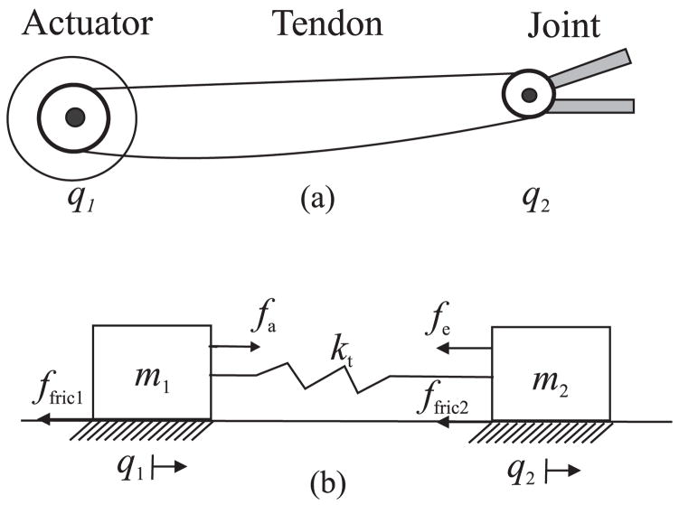
Friction modeling is required for model-based friction compensation. We consider the friction that occurs in a joint of a manipulator at several stages of power transmission. As an example, we consider the tendon-driven joint of Figure 2 that consists of an actuator, a joint, and a tendon that connects the actuator to the joint. The tendon is modeled by a nonlinear spring. The dynamic equations of the tendon joint are written as [10], [11]:
| (6) |
where q1 is the position of the actuator, q2 is the position of the joint, m1 and m2 are the mass values (or the rotational inertias) of the actuator and the joint, c1 and c2 are damping coefficients, ft is the force transmitted through the tendon, kt(·) is the force-displacement response of the tendon, fa is the generated force by the actuator, fe is the environment force applied to the joint, ffric1 is the friction force of the actuator, and ffric2 is the friction force of the joint. It is assumed that m1, m2, c1, and c2 are constant. The displacement of the joint is different from the displacement of the actuator due to the tendon stretch.
Fig. 2.
(a) A tendon-driven joint that consists of an actuator, a joint, and a tendon that connects the two, and (b) a network of two mass components, a spring, and two friction surfaces that model a tendon-driven joint.
In order to clarify the analysis of friction compensation, we temporarily assume
| (7) |
A Coulomb model is used to model the friction in the joint.
| (8) |
where fcb2 is the Coulomb friction level. Since only the displacement of the actuator is available to the controller of the tendon-driven joint, the friction in the joint should be estimated from this displacement. As long as the actuator and the joint are undergoing sliding displacements in the same direction, the friction can be accurately calculated. Otherwise, the controller cannot accurately estimate the friction force of the joint.
III. Model-Based Friction Compensation
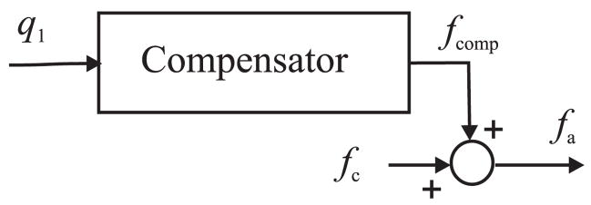
A model-based compensation approach is used to cancel friction in a joint of a teleoperator. A feedforward force fcomp is calculated based on a friction model and is added to the teleoperator control force, fc, to obtain the force that should be applied by the actuator (Figure 3)
Fig. 3.
Model-based friction compensation for a tendon-driven joint. q1 is the displacement of the joint, fcomp is the compensator force, fc is the teleoperator control force, and fa is the force applied by the actuator.
| (9) |
We introduce a single-state friction compensator to estimate friction in a joint of a teleoperator. It is shown that the friction compensator enhances the transparency of a teleoperator and preserves the passivity of the teleoperator.
A. Single-State Elastic Friction Compensator
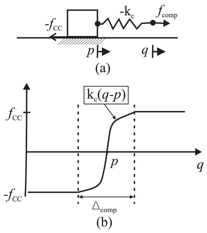
The single-state elastic friction compensator consists of a slider and a spring that are serially connected (Figure 4a). Displacement q is the input to the friction compensator, and the force applied to the spring is the output. A Coulomb model calculates resistant forces applied to the slider when it moves. The compensator model is obtained by:
| (10) |
where p is the position of the slider, fCC is the Coulomb friction level of the compensator, kc(·) is the force-displacement response of the (possibly nonlinear) spring (Figure 4b), and Δcomp is the breakaway distance of the compensator [22].
Fig. 4.
Single-state elastic friction compensator. (a) The compensator is represented by a slider and a nonlinear spring that are serially connected. Since the friction compensator is an active element, its spring and Coulomb friction level are negative. (b) Force-displacement response of the compensator.
For discrete-time implementation, the position of the slider is calculated by [22]
where pk and pk−1 represent the position of the slider at time tk and tk−1 respectively and qk−1 is the input position at tk−1. The output force is calculated based on the position of the slider and the input position. When the spring is slightly pulled , the slider does not move (pk = pk−1) and the level of output force is calculated by kc(qk − pk). When spring stretch reaches to a maximum level , the level of output force reaches the Coulomb level fCC, and the slider starts moving.
The single-state elastic friction model of (10) (for a linear kc(·)) is a special case of the elastic-plastic model of [18]. It is difficult to prove the passivity of the friction compensation for an elastic-plastic compensator because it is hard to calculate the energy of the compensator during plastic presliding.
B. Effect on Transparency
The friction compensator (10) increases the transparency of the tendon-driven joint (6) when fCC ≤ fcb2 and the slider is moving. The total friction force of the joint after compensation is calculated by the summation of the actual friction force in the joint and the friction force of the compensator. When the slider moves, the total friction force is fcb2 − fCC. When the slider stopes, the total friction force is kt(q2 −q1)−kc(q1 −p). Using a force-displacement function kc(·) close to kt(·) can increase the accuracy of friction estimation. However, the slider may not stop at the same time that the joint stops, therefore full cancellation of friction is not possible.
C. Passivity of friction compensation
The friction compensator (10) is an active element, so the energy generated by the compensator has the potential to destabilize the teleoperator. We use passivity theory to prove that the single-state friction compensator (10) preserves the passivity of the tendon-driven joint (6), (7), (8) in the control structure (9) (Figure 3) under certain parameter restrictions.
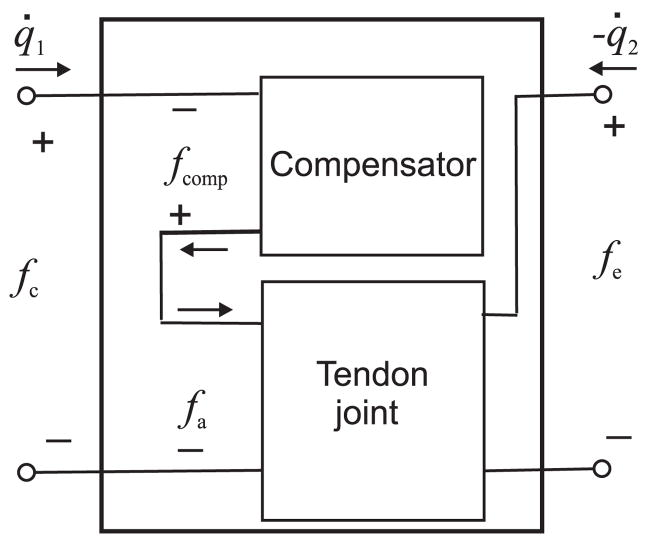
We use a network representation of the friction compensation for a tendon-driven joint to study the passivity of compensation (Figure 5). The friction compensator is represented by a one-port network. The tendon joint is represented by a two-port network. These two networks are combined into one two-port network. In the following, we show that the combined network is passive under certain conditions. Passivity of the network preserves the stability of the teleoperator.
Fig. 5.
Network representation of a model-based friction compensator and a tendon-driven joint of a teleoperator. A one-port network represents the friction compensator, and a two-port network represents the tendon joint. Two networks combined into one two-port network.
Definition I
Following [23], a system with flow v, effort f, and initial energy e0 (v(t), f(t) ∈ ℝn) is passive if
| (11) |
for all f and v, and t ≥ 0.
Definition II
Operator D is defined for a signal x(t) as:
| (12) |
When x(t) represents the displacement of a point, D(x) represents the total distance traveled by x(t) during [0 t].
Theorem I
Considering the two-port network of Figure 5, the network is passive if
fCC ≤ fcb2
Δtendon ≤ Δcomp where Δtendon is the maximum displacement lag between the actuator and the joint.
Proof
In order to clarify the proof, we consider that the initial velocities and initial extension of the tendon-driven joint are zero, and the initial extension of the compensator spring is at its minimum: q̇1(0) = 0, q̇2(0) = 0, q1(0) − q2(0) = 0, . For arbitrary initial conditions, a larger energy constant e0 can be obtained such that the passivity condition is always satisfied.
Using Definition I, the passivity condition for the network of Figure 5 is written as:
| (13) |
Given fc = fa − fcomp, we write
| (14) |
By integrating this condition with the joint model (6), (7), (8), we have
The integral term is calculated as:
where ξ = q1 − q2. Since the energy terms due to mass, damping and spring components of the tendon-driven joint are always positive values, they can be omitted from the passivity condition to obtain
| (15) |
Given the compensator model (10), we write
| (16) |
where ξ = q1 − p and calculates the elastic energy of the compensator spring. This energy is bounded
| (17) |
Using (16) and (17), the passivity condition (15) is satisfied if
| (18) |
Using Definition II, the above condition is written as
| (19) |
Given the first assumption of Theorem I, (19) is satisfied if
| (20) |
or
| (21) |
The above condition relates the passivity of the friction-compensated tendon joint to distances traveled by the slider and the joint. We consider two trajectory cases to evaluate D(p) − D(q2):
-
The slider does not change direction.
The distance between p and q2 cannot become longer than the total stretch of the tendon and the spring of the friction compensator, therefore for this case
(22) Given the second assumption of Theorem I, (22) concludes:
(23) -
The slider changes direction.
When the slider changes direction, the actuator (which causes the slider to move) should displace longer than the maximum stretch of the spring of the compensator Δcomp (Figure 6). Then, given the second assumption of Theorem I, the actuator should enforce the joint to change direction and displace longer than the slider. Therefore, for a loop trajectory traveled by the slider, the joint travels a longer distance:
Fig. 6.
Diagram of the combination of a single-state elastic friction compensator and a tendon-driven joint. The actuator pulls the slider and the joint through the springs. The negative sign indicates that the spring pushes the actuator when it is extended.
| (24) |
For any possible slider motion (considering both cases above and (23) and (24)), we generally conclude
| (25) |
If we define e0 = 2fcb2Δcomp, using (25) will result in (21) and consequently the passivity of the joint.
D. Multiple Single-State Elastic Friction Compensator
Several single-state elastic friction models can be used together to passively compensate friction in a joint when friction occurs in several places of a compliant joint. The theorem of the last section is extended to the multiple elastic models used for multiple friction places with these conditions: (1) The Coulomb friction level of each friction model should be smaller that the Coulomb friction level of its corresponding friction surface. (2) The breakaway distance of each friction model should be larger than the displacement lag between the corresponding friction surface and the compensator output. For example, if the friction of the actuator is not zero for model (6), ffric1 ≠ 0, a single-elastic friction with a small Δcomp1 can added to the compensator to cancel friction of the actuator. The total compensator force is obtained from two single-state models (10)) as
| (26) |
where kc1(·) and kc2(·) are the force-displacement responses of the springs and p1 and p2 are the positions of the sliders of the models.
IV. Implementation and Experimental Results
This friction compensation method was implemented to experimentally evaluate its effect on transparency and the passivity of a position-tracking teleoperator.
A. Experimental Setup
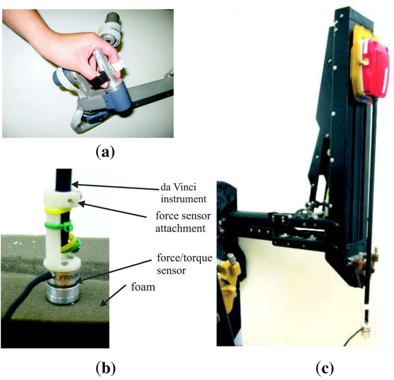
The experiments were conducted on a custom version of the da Vinci telerobotic system from Intuitive Surgical, Inc. (Sunnyvale, USA) (Figure 7). The telerobotic system contains two master manipulators and two slave manipulators provided by Intuitive Surgical, Inc., and a custom control system developed at the Johns Hopkins University [24].
Fig. 7.
The custom da Vinci surgical system components used in the experiments: (a) master telemanipulator (MTM), (b) setup for measuring force responses of contact with a soft object, and (c) patient-side manipulator (PSM).
The custom control system implements the control structure (2) with the translation gain
| (27) |
Friction compensation is only used for the joints of the slave manipulators, since friction in the joints of the master manipulators is small.
B. Parameters of Friction Compensators
We report the results of identifying the parameters of the friction compensator for the prismatic joint (Figure 7c). During an identification test, we use the position-tracking teleoperator (27) to define the parameters of the friction compensator for the prismatic joint. An operator moved the master manipulator to direct the prismatic joint of the slave manipulator to displace back and forth at low velocities and accelerations. Coulomb friction dominates over inertial forces and viscous friction at low velocities and accelerations.
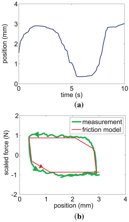
Figure 8 shows the displacement and the measured force-displacement response of the actuator of the prismatic joint during the identification test. The forces were obtained from the currents applied to the actuator. A multiple single-state elastic friction compensator (26) was fit to the measured actuator force-displacement. The friction compensator included two single-state elastic friction models with linear springs. The parameters of the models were selected such that the the force-displacement loop generated by the two friction models fit the measured force-displacement loop closely while keeping the area of the force-displacement loop of the models smaller than the area of the measured force-displacement loop to ensure passivity. The parameters of the friction models were estimated to be
Fig. 8.
(a) Displacement response of the prismatic joint during identification, and (b) force-displacement of the joint and the friction compensator. The friction compensator obtains a piecewise linear approximation of the measured force-displacement hysteresis loop.
| (28) |
Throughout this article, the reported force parameters and force responses are linearly scaled from their actual values in order to protect proprietary data of Intuitive Surgical, Inc.
We performed a similar identification test when the environment force was about 3.0 N. The friction parameters obtained during the new test were very close to the identified parameters of the first test. This shows that the effect of environment force on the friction parameters is negligible. If the friction parameters depended on the environment force, the smallest Coulomb friction level and the largest breakaway distance obtained for a range of the environment force could be used to provide passive compensation.
C. Transparency and Passivity
Two tests were performed to evaluate the effect of friction compensation on transparency of the position-tracking teleoperator (27) with the compensator (28). During the first test, an operator used the teleoperator to probe a piece of foam (Figure 7b). The foam surface was pressed down with the tip of the slave manipulator along the prismatic joint of the slave and the normal to the surface of the foam. No friction compensation was applied during the first test. A Nano-17 ATI force sensor attached to the tip of the slave manipulator measured the force between the manipulator and the foam. The forces that the operator applied to the master manipulator during the first test were estimated by the torques applied by the actuators to the tip of the master manipulator. The torques were calculated by the currents applied to the actuators. We did the second test similar to the first one while the friction was compensated using (28).
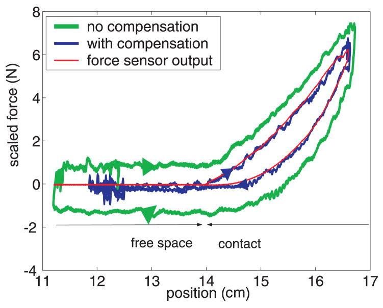
For a transparent teleoperator, the force-displacement response of contacting the environment should be equal to the force-displacement response of the operator. Figure 9 shows three force-displacement responses: (1) the force-displacement response of the probing the foam measured by the force sensor during the first test, (2) the estimated force-displacement response of the operator during the first test, and (3) the force-displacement response of the operator during the second test. The force of the operator is estimated from currents applied to the actuators of the master manipulator. The force-displacement response of the operator during the second test is close to the force-displacement response of the foam (environment). We conclude that friction compensation significantly increases the match between the force-displacement curves of the foam and the operator and enhances the transparency of the teleoperator.
Fig. 9.
Force-displacement curves of a teleoperator during probing of a soft object along normal to the surface of the object. The force curves include the force-displacement response of probing the soft object, and the force-displacements at the end effector of the master manipulator when friction is compensated and the same response when friction is not compensated.
The force-displacement responses of the operator is not very close to the force-displacement response of the foam at displacements 12.0 cm and 16.6 cm during the second test. At these points, the operator switched the direction of motion. Switching the motion direction causes the sliders of the friction compensator to stop for a range of displacements of the operator and friction is not as effectively canceled at these points. Considering friction compensator parameters (28) and the controller gain (27), the displacement distance for which the friction compensator did not provide full compensation is 0.8 mm. This displacement is negligible compared to the 26 mm penetration depth into the foam sample. Whether a displacement distance is negligible for a surgical task depends on the range of environment forces and the displacements involved during that task.
The stability of the teleoperator interactions with various environments including foam, rubber, and metal and operator motions including slow, sudden, and fast oscillatory movements during friction compensation were tested. The teleoperator was stable during all the tests.
V. Conclusions
A friction compensator with multiple single-state elastic friction models was introduced to cancel friction in the joints of the manipulators of a teleoperator with compliant transmission. The parameters of the compensator were selected to preserve the passivity of the teleoperator. The compensator almost fully cancels the Coulomb friction of each joint when all friction surfaces of the joint moves in the same direction.
Acknowledgments
The authors thank Ankur Kapoor and Dr. Peter Kazanzides for their contributions in designing the electronic hardware for the teleoperator, and Intuitive Surgical, Inc., Sunnyvale, CA, USA for access to the da Vinci hardware.
This work supported in part by National Science Foundation Grant No. EIA-0312551, National Institutes of Health Grant No. R01-EB002004, and Whitaker Foundation Grant No. RG-02-911.
Contributor Information
Mohsen Mahvash, Email: mah-vash@jhu.edu, Engineering Research Center for Computer Integrated Surgical Systems and Technology (ERC-CISST), the Johns Hopkins University, Baltimore, MD 21218 USA.
Allison Okamura, Email: aokamura@jhu.edu, Department of Mechanical Engineering, the Johns Hopkins University.
References
- 1.Hashtrudi-Zaad K, Salcudean SE. Transparency in time-delayed systems and the effect of local force feedback for transparent teleoperation. IEEE Transactions on Robotics and Automation. 2002;18(1):108–114. [Google Scholar]
- 2.Armstrong-Helouvry B, Dupont P, Canudas C. A survey of models, analysis tools and compensation methods for the control of machines with friction. Automatica. 1994;30(7):1083–1138. [Google Scholar]
- 3.Dupont P. Avoiding stick-slip through PD control. IEEE Transactions on Automatic Control. 1994;39(5):1094–1097. [Google Scholar]
- 4.Makkar C, Dixon WE, Sawyer WG, Hu G. Lyapunov-based tracking control in the presence of uncertain nonlinear parameterizable friction. IEEE Transactions on Robotics and Automation, to apear [Google Scholar]
- 5.Olsson H, Astrom KJ, Canudas C, Gafwert M, Lischinsky P. Friction models and friction compensation. European J of Control. 1998;4(3):176–195. [Google Scholar]
- 6.Olsson H, Astrom KJ. Observer-based friction compensation. Proceedings of the 35th IEEE Conf. on Decision and Control; Kobe, Japan. 2002. pp. 68–74.pp. 4345–4350. [Google Scholar]
- 7.Vedagarbha P, Dawson DM, Feemster M. Tracking control of mechanical systems in the presence of nonlinear dynamic friction effects. IEEE Transactions on Control Systems Technology. 1999;7(4):446–456. [Google Scholar]
- 8.Bernstein L, Lawrence DA, Pao LY. Friction modeling and compensation for haptics interfaces. Proc. World Haptics; Pisa, Italy. 2005. pp. 290–295. [Google Scholar]
- 9.Bi D, Li YF, Tso SK, Wang GL. Friction modeling and compensation for haptic display based on support vector machine. IEEE Transactions on Industrial Electronics. 2004;51(2):491–500. [Google Scholar]
- 10.Hayward V, Cruz-Hernandez MJ. Parameter sensitivity analysis for design and control of tendon transmissions. In: Khatib O, Salisbury JK, editors. Experimental Robotics IV. Lecture Notes in Control and Information Sciences. Vol. 223. Springer-Verlag; 1997. pp. 241–252. [Google Scholar]
- 11.Frisoli A. PhD thesis. Scuola Superiore SantAnna; Pisa: 2002. Design and modeling of haptic interfaces: an integrated approach. [Google Scholar]
- 12.Townsend WT, Salisbury JK. The effect of coulomb friction and stiction on force control. IEEE International Conference on Robotics and Automation; 1987. pp. 143–151. [Google Scholar]
- 13.Ferretti G, Magnani G, Rocco P. Impedance control for elastic joints industrial manipulators. IEEE Transactions on Robotics and Automation. 2004;20(3):488–498. [Google Scholar]
- 14.Dahl P. Solid friction damping of mechanical vibrations. AIAA Journal. 1976;14(2):1675–82. [Google Scholar]
- 15.Mahvash M, Okamura A. Friction compensation for a force-feedback telerobotic system. IEEE International Conference on Robotics and Automation; Orlando, Florida. 2006. pp. 3268–3273. [Google Scholar]
- 16.Mahvash M, Okamura A. Friction compensation for a force-feedback teleoperator with compliant transmission. 45th IEEE Conf. on Decision and Control; San Diego, CA. 2006. pp. 4508–4513. [Google Scholar]
- 17.Palli G, Melchiorri C. Model and control of tendon-sheath transmission systems. IEEE International Conference on Robotics and Automation; Orlando, Florida. May 2006; pp. 988–993. [Google Scholar]
- 18.Dupont P, Hayward V, Armstrong B, Altpeter F. Single state elasto-plastic friction models. IEEE Transactions on Automatic Control. 2002;47(5):787–792. [Google Scholar]
- 19.Yokokohji Y, Yoshikawa T. Bilateral control of master-slave manipulators for ideal kinesthetic couplingformulation and experiment. IEEE Transactions on Robotics and Automation. 1994;10(5):605–620. doi: 10.1109/70.326566. [DOI] [PubMed] [Google Scholar]
- 20.Hannaford B. A design framework for teleoperators with kinesthetic feedback. IEEE Transactions on Robotics and Automation. 1989;5:426–434. [Google Scholar]
- 21.Lawrence DA. Stability and transperancy in bilateral teleoperation. IEEE Transactions on Robotics and Automation. 1993;9(5):624–637. [Google Scholar]
- 22.Hayward V, Armstrong B. A new computational model of friction applied to haptic rendering. In: Corke PI, Trevelyan J, editors. Experimental Robotics VI. Lecture Notes in Control and Information Sciences. Vol. 250. Springer-Verlag; 2000. pp. 403–412. [Google Scholar]
- 23.Lozano R, Brogliato B, Egeland O, Mashke B. Dissipative systems, analysis and control, theory and applications. New York: Springer-Verlag; 2000. [Google Scholar]
- 24.Kapoor A, Simaan N, Kazanzides P. A system for speed and torque control of DC motors with application to small snake robots. IEEE Intl. Conf. Mechatron. and Robot; 2004. [Google Scholar]


