

Abstract
The aim of this study was to develop a novel method to encapsulate magnetic nanoparticles (MNPs) with polymer via covalent bonding, in order to increase the magnetic nanoparticle stability and ease the synthesis process. In this technique, silane coated MNPs act as a template for polymerization of the monomer N-isopropylacrylamide, (NIPA) via radical polymerization. Transmission and scanning electron microscopy indicated the size of the original MNP was approximately 10 nm, the silane-coated MNP was 40 nm and the NIPA silane-coated MNP was 100 ± 10 nm. Chemical composition and chemical state analysis of NIPA MNPs by FTIR and XPS showed that the MNPs were actually encapsulated by silane and NIPA. Furthermore, the magnetic properties of different layers on the MNP, analyzed by SQUID, indicated a decrease in saturation magnetization for each layer. The results demonstrate the feasibility of encapsulation of the MNP with NIPA by means of silane covalent bonding. Future work will investigate the phase transition and biocompatibility properties of the NIPA-coated MNP for drug delivery and tissue engineering applications.
1. INTRODUCTION
Magnetic nanoparticles (MNPs) have been attracting much attention because of their applications in various fields, especially in biotechnology and medicine. These applications include cell separation, DNA/RNA purification, immunoassays, contrast agents in magnetic resonance imaging (MRI), magnetic targeted drug carriers, tissue engineering, and hyperthermia treatments for cancer.1, 2 Coating magnetic particles with biocompatible polymers has been done to produce polymeric MNPs for medical applications.3–5 This type of magnetic core-polymeric shell structure can also increase the dispersion and stability of such nanoparticles.
A variety of polymers have been explored for production of these polymeric/MNPs. Some examples include natural polymers such as albumin, cellulose, pullulan, and chitosan, as well as synthetic polymers like polystyrene, poly acrylamide, and poly(L-lactic-co-glycolic)acid.1 2 6 7 In addition, magnetic nanoparticles encapsulated by dextran or liposomes are well-known in drug and gene therapy delivery applications.8–14 Thermo-sensitive polymers, including poly N -isopropylacrylamide (NIPA) have also been adopted for hyperthermia treatments.2 15–17 The temperature sensitivity of NIPA is manifested by a reversible volume phase transition at a lower critical solution temperature (LCST) of 32 °C, where the hydrogel hydrophobically collapses upon itself, expelling water in an entropically-favored fashion. This reversible swelling and shrinking event has been used as a means to control the uptake and release of various therapeutic agents. The LCST of a NIPA copolymer, poly(N-isopropylacrylamide-co-acrylamide) can be increased to slightly above body temperature, 37 °C.15–17
Several methods have been applied to generate polymeric/MNPs, including traditional coating, emulsion polymerization, mini-emulsion polymerization, in situ polymerization, and photochemical polymerization.2 5 18–21 Some of these techniques, however, involve complex processes, leading to excessive time and expense in production of the shelled polymeric/magnetic nanoparticles. Some polymer encapsulation techniques also do not provide a strong chemical bond to the magnetic core. If the polymer is desorbed or ruptured, the magnetic particles are exposed to the biological environment, leading to biocompatibility problems. It is also possible that magnetic nanoparticles diffuse out of the polymer matrix, defeating the purpose of the magnetic-based nanoparticle.18 These problems suggest the need to find a new synthetic way to coat magnetic nanoparticles with polymers where size can be controlled, for example, by a surfactant. Template-mediated polymerization has been used to synthesize microparticles for drug delivery,22 however, downsizing to nanoparticles offers significant advantages, especially for intracellular drug delivery.
In this paper, we present an alternative approach to synthesis of polymeric magnetic nanoparticles that have a variety of potential applications in drug delivery. Two synthetic steps were used to prepare the nanoparticles. First, magnetic nanoparticles were covalently bound with vinyltrimethoxysilane (VTMS) to produce a template site for radical polymerization. N-isopropylacrylamide (NIPA) was then polymerized on the silicon layer around the MNPs. The morphology and size of nanoparticles were determined using scanning electron microscope (SEM) and transmission electron microscope (TEM). The chemical composition of each layer around the magnetic nanoparticles was confirmed by Fourier transformed infrared spectroscopy (FTIR) and X-ray photoelectron spectroscopy (XPS). Finally, magnetic properties after each encapsulation of the magnetic nanoparticles were assessed using a superconducting quantum interference device (SQUID).
2. MATERIALS AND METHODS
2.1. Materials
Ferric chloride hexahydrate and ferrous chloride tetrahydrate were purchased from Fluka. Sodium hydroxide, sodium dodecyl sulfate (SDS), docusate sodium salt (AOT), potassium persulfate (KPS), methylene-bis-acryla-mide (BIS), vinyltrimethoxysilane (VTMS), acetic acid, ethanol, and methylene-bis-acrylamide were purchased from Aldrich and used as received.
2.2. Preparation of Magnetic Nanoparticles
Magnetic nanoparticles were prepared by a conventional co-precipitation method.23 In brief, ferric chloride hexahydrate and ferrous chloride tetrahydrate (2:1) were dissolved in DI water. After purging with argon gas, AOT was added as surfactant, and the solution was heated to 85 °C. At this temperature, 7.1 M NaOH was added. After a 2 hour reaction period, particles were washed extensively with ethanol and then centrifuged. The pellet was dried in a vacuum oven before further steps were undertaken.
2.3. Preparation of VTMS–Coated Magnetic Nanoparticles
The magnetic nanoparticles were coated with VTMS via acid catalyst hydrolysis, followed by electrophilic substitution of ferrous oxide on the surface of the magnetic nanoparticles as shown in Figure 1(a). In brief, VTMS was hydrolyzed using acetic acid in the presence of water and ethanol. Magnetic nanoparticles were then dispersed by sonication at 100 W for 30 minutes in this solution; the product was then obtained after 24 hrs of vigorous mechanical stirring at room temperature. The product was excessively washed with a mixture of water/ethanol (1:100 v/v), and the particles were dispersed in water before the next step.
Fig. 1.
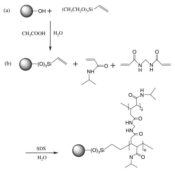
Preparation procedure of (a) coated magnetic nanoparticles with VTMS and (b) immobilization of NIPA on magnetic nanoparticle surface.
2.4. Immobilization of NIPA on Surface of Magnetic Nanoparticles
VTMS-coated magnetic nanoparticles were used as template to polymerize NIPA in an aqueous micellar solution as shown in Figure 1(b). SDS and BIS were used as surfactant and cross linking agent, respectively, as previously described.24 In brief, VTMS-coated magnetic nanoparticles, NIPA, BIS, and SDS were sonicated in cold water for 30 minutes. Then, the mixture was heated to 70 °C and a potassium persulfate initiator was added. The solution was stirred under Argon for 4 hours. The product was purified several times with DI water by using a magnet to collect only NIPA-coated magnetic nanoparticles.
2.5. SEM and TEM Studies
SEM (ZEISS Supra 55 VP) was used to analyze the aver-age size and morphology of the synthesized nanoparticles. Samples were prepared by coating dried nanoparticles with gold on a silicon wafer. In addition, TEM (JEOL 1200 EX) was used to determine the size and core–shell structure of these nanoparticles. In general, samples were prepared by drop casting an aqueous dispersion of nanoparticles onto a carbon coated copper grid and the grid was dried at room temperature before viewing under the microscope. NIPA/MNPs were stained with phosphotungstic acid at a concentration of 0.01% before analysis.
2.6. FTIR Studies
Dried samples were ground with KBr and the mixture was compressed into pellets. FTIR spectra were recorded in the transmission mode using a Bruker VECTOR 22 spectrometer. The spectrum was taken from 4000 to 400 cm−1.
2.7. XPS Studies
XPS measurements were carried out on the synthesized particles on a Perkin-Elmer PHI560 ESCA/SAM system using an Al Kα 1486.6 eV X-ray source. The resolution of the analyzer was 0.5 eV. Deconvolution was carried out with Gaussian functions. Chemical states of various elements were obtained by using binding energies from the literatures. The atomic percentage of the elements present in the particles was calculated from the ratio of the net intensities of corresponding peaks, corrected using the instrument’s sensitivity factors.
2.8. SQUID Measurements
A magnetic property measurement system with a SQUID-based magnetometer (Quantum Design) was used to obtain room temperature magnetic hysteresis loops for MNPs, silane-coated MNPs, and NIPA MNPs. Pre-weighed samples were placed in a gelatin capsule and the capsule, with sample, was mounted in a transparent drinking straw wherein the measurement was obtained.
3. RESULTS AND DISCUSSION
In this work we intended to encapsulate magnetic nanoparticles with a temperature-sensitive polymer, NIPA, via covalent bonding. Encapsulation of magnetic nanoparticles covalently is important because it can increase nanoparticle stability to ensure essential function of magnetic drug delivery. To functionalize the magnetic nanoparticles, a silane coupling agent was used to attach magnetic nanoparticles to silicon at one end while a carbon–carbon double bond at the other end provided a site for radical polymerization. In the second step, NIPA was polymerized on the surface of a silane coupling agent, and the size of the nanoparticles was adjusted by a surfactant. To characterize the nanoparticles, several complementary techniques such as SEM, TEM, FTIR, XPS, and SQUID were used. The results from each characterization method are discussed below.
3.1. Size, Morphology, and Core–Shell Structure of Nanoparticles
The average size of the synthesized magnetic nanoparticles and their derivatives was analyzed using TEM and SEM. The size of the magnetic nanoparticles was in the range of 10 nm in diameter as shown in Figure 2(a). The electron diffraction pattern in Figure 2(a) consists of continuous rings consistent with the small size and large number of the magnetic nanoparticles. The first four diffraction rings had d-spacings of 4.771, 2.943, 2.511, 2.062 Å and were indexed to correspond to the (111), (220), (311), and (400) planes of the Fe2O3 structure. The average size of MNPs coated with the silane coupling agent, as determined by TEM, was around 40 nm, Figure 2(b). The larger size of the silane-coated particles is attributed to agglomeration of a few MNPs during the encapsulation process. Single crystal nanoparticles of that scale usually exhibit crystallographic facets to reduce their surface energy. It is possible that facets of the same orientation were merged together to produce a larger size particle. In that case, the electron diffraction pattern, Figure 2(b), which was taken from a couple of silane-coated particles, consists of several spots of the same crystal structure as that of Figure 2(a). This is consistent with the argument that the larger, silane-enclosed particles are composed of a merged 10 nm MNPs. NIPA silane-coated MNPs were about 100 nm in size, as shown in Figure 2(c). Further-more, Figure 2(c) clearly indicates the formation of silane-coated magnetic nanoparticles with uniform shells. A close examination of the TEM image, inset in Figure 2(c), shows that each dark core magnetic nanoparticle was surrounded by a thin (~2 nm), lighter shell from silane and a thicker, uniform NIPA shell. It is important to note that the NIPA shell formed around the large silane-coated particle rather than around an agglomeration of silane-coated particles. This is markedly different than the results observed with other encapsulation methods such as miniemulsion.25 This provides evidence that each individual silane-coated magnetic nanoparticle serves as a template site for polymerization of NIPA. SEM analysis also confirmed the results for the shapes and sizes of the synthesized nanoparticles (data is not shown).
Fig. 2.

Transmission electron micrograph of coated and uncoated magnetites: (a) As-synthesized magnetic nanoparticles (inset is the diffraction pattern); (b) Silane-coated magnetic nanoparticles (inset is the diffraction pattern); (c) NIPA-coated magnetic nanoparticles (inset is a higher magnification image).
3.2. Chemical Analysis of Nanoparticles
FTIR and XPS were used to characterize the chemical compositions of nanoparticles after each synthesis step.
3.2.1. FTIR Studies
Comparison of FTIR spectra for coated and uncoated magnetic nanoparticles clearly indicates the presence of the silane coupling agent and NIPA. Our FTIR analysis of uncoated magnetic nanoparticles is in agreement with the absorption characteristics of Fe–O as a broad feature inthe low wavelength region at 412.1 cm−1, 568.7 cm−1 and 583.4 cm−1 as observed by other investigators.23 However, silane coated magnetic nanoparticles show a shift in these regions to higher wavelengths, 583.2 cm−1 and 595.1 cm−1, which indicates the presence of a silane group instead of hydrogen. Furthermore, the carbon–carbon double bond at 1625 cm−1 of VTMS disappeared in our final product, the NIPA-silane coated magnetic nanoparticle, due to polymerization with NIPA and BIS. The presence of an absorbance peak at 1120 cm−1 indicates the presence of the isopropyl group, and at 1644.4 cm−1, the carbonyl group on NIPA.
3.2.2. XPS Studies
XPS was used to determine the composition and bonding structures of the synthesized nanoparticles.Figure 3 presents the general XPS spectra of the (a) Fe2O3 particles, (b) silane-coated Fe2O3 particles, and (c) NIPA-coated Fe2O3 particles. As shown, strong O 1s and Fe 2p peaks at 530 eV and 711.5 eV, respectively, are present in the Fe2O3 particle spectrum. In addition, a weak C 1s peak at 285.9 eV can also be seen. The intensity of this peak was significantly reduced by increasing sputtering time, indicating that this peak may originate from contamination. Three peaks corresponding to C 1s, O 1s, and Fe 2p electrons can be seen in the spectrum for the silane-coated Fe2O3 particles. The intensity of the C 1s peak is slightly higher and that of the Fe 2p peak lower in the spectrum for the silane-coated Fe2O3 particles as compared with the spectrum for the Fe2O3 particles. This implies that the Fe2O3 particles are coated with a silane layer. At the same time, a very weak Si 2p peak at a binding energy of 101.86 eV could be distinguished from the background, indicating the existence of Si in the coating. In the spectrum of NIPA-coated Fe2O3 particles, two strong C 1s and O 1s peaks appear. After careful inspection, three weak peaks originating from Si 2p, N 1s, and Fe 2p could be distinguished. The calculated composition of the elements in the NIPA-coated particles is 4.6% for Si, 21.1% for O, 70.9% for C, 3% for Fe, and 0.1% for N. The low content of the Si and Fe in this sample indicates that the Fe2O3 particles might be completely covered with a relatively thick NIPA layer.
Fig. 3.

XPS spectra from the (a) Fe2O3 particles, (b) silane coated Fe2O3 particles, and (c) NIPA-coated Fe2O3 particles.
In order to obtain detailed information about the chemical bonds for the NIPA coated particles, high resolution scans were performed for the various elements involved. Figure 4(a) exhibits the N 1s spectrum of the NIPA-coated particles. Due to the low intensity, the N 1s spectrum of the Fe2O3 particles is also included in the figure as a reference. The results clearly show the presence of nitrogen in the NIPA-coated particles. This peak can be deconvolved with a Gaussian peak at 400.33 eV, which is close to the binding energy of N 1s in imine- or aromatic-type  bonding, 400.6 eV.26, 27 This indicates that the N 1s peak in the spectrum originates from NIPA.
Fig. 4.

High resolution deconvoluted spectra from (a) N 1s, (b) Si 2p, (c) Fe 2p1/2, (d) O 1s, and (e) C 1s of the NIPA-coated particles.
Figure 4(b) depicts the Si 2p high resolution spectrum obtained from the NIPA-coated particles. The Si 2p peak is at about 102 eV, which is lower than the binding energy of Si 2p in the Si–O bond (103.3 eV), but higher than that in the Si–C bond (101.2 eV). This indicates the existence of both Si–C and Si–O bonds in the particles. In a previous study of the oxidation behavior of SiC, Jernigan et al. also found that the Si 2p peak shifts to a higher binding energy due to the formation of Si–O bonds.28 The Si 2p peak could be deconvolved using the two chemical states of Si at 101.2 and 103.3 eV. The relative intensity ratio for the two peaks is about 1, indicating that each Si atom in the particles is bonded with both O and C and suggesting that only a Si atom monolayer covers the Fe2O3 particles.
Figure 4(c) shows the Fe 2p1/2 high resolution spectrum from the NIPA-coated particles. The peak can be deconvoluted with one Gaussian peak at 711.7 eV, which is close to the binding energy of Fe 2p1/2 in Fe(OOH) (711.3 eV) and Fe2O3 (710.9 eV). The peak is broad, implying the existence of both Fe(OOH) and Fe2O3 phases in the synthesized Fe2O3 particles.
Due to the existence of Fe–O,  , and Si–O bonding, the O 1s spectrum should be fitted with three peaks corresponding to 529.6, 531.9, and 532.9 eV (Ref. [29]) as shown in Figure 4(d). The relatively content of the Fe–O,
  , and Si–O bonds is calculated to be 24.5%, 27.9%, and 47.6%, respectively.
On the basis of the above analysis, there should exist C–Si, C–N, and  bonds in the NIPA coated particles. According to the chemical molecular formula of NIPA, there should also be CHn/C–C bonds. Therefore, the C 1s spectrum should be fitted with 3 peaks at 282.7, 284.8, 286, 288.4 eV, corresponding to the C–Si, CHn/C–C, C–N, and
  bonds, respectively, as shown in Figure 4(e). The relatively content for different bonding is calculated to be 3.4%, 90.8%, 2.0%, and 3.8%, respectively. The high content of the CHn/C–C bond indicates that 90% of C in the spectra originates from NIPA.
3.3. Magnetic Properties
Room temperature magnetization measurements of magnetic nanoparticles, silane coated magnetic nanoparticles and NIPA coated magnetic nanoparticles were determined using a SQUID-based magnetic property measurement system (Fig.5). The magnetic nanoparticles and the two layers can be classified as soft ferromagnetic substance. These types of substances are classified by their low coercive force (<102 Oe), small remanent magnetic induction, and long and narrow hysteresis loop.30 The measured values of magnetic properties of each type of nanoparticles are shown in Table I.
Fig. 5.

Magnetic hysteresis curve of magnetic nanoparticles, silane coated, and NIPA coated magnetic nanoparticles at room temperature.
Table I.
Magnetic properties of nanoparticles.
| Sample | Saturation magnetization (Ms) emu/g |
Remanence (Mr /Ms) |
Coercivity (Hc) Oe |
|---|---|---|---|
| MNPs | 70.861 | 11.42 | 9.53 |
| Silane coated MNPs | 40.217 | 5.53 | 26.69 |
| NIPA coated MNPs | 29.714 | 4.28 | 42.42 |
The saturation magnetization of the MNPs in this study (70.86 emu/g) was lower than that of bulk iron oxide (87.25 emu/g) but in good agreement with previous studies on iron oxide nanoparticles.34 Similar effects have been well documented in the literature and attributed to non-linear spin configuration on the surface, resulting from the incomplete or different surroundings of the surface atoms.31 32 The saturation magnetization of magnetic nanoparticles was decreased by 43.2% after coating with silane and by 58.1% after coating with NIPA. These results are attributed to contributions of a magnetically “dead” surface layer reported to be present on the surface of particles.33 A simple calculation shows that in 10 nm size particles about 40% of the atoms are at the surface that has reacted with silane. Thus, the expected saturation magnetization of the silane-coated particles is in good agreement with the measured value. Also, the coercivity was found to increase as the MNPs were sequentially coated with silane and NIPA. This increase is attributed to size effects and an increase in separation distance of nanoparticles as a result of coating. Decreasing saturation magnetization was noticeable when magnetic nanoparticles were placed in an external magnetic field where their respond time increased. This increase in response time has both advantages and disadvantages. By decreasing the saturation magnetization and increasing the response time, the aggregation of magnetic based nanoparticles (e. g., polymeric magnetic nanoparticles) decreases; however, at the expense of having to use a higher external magnetic field to remotely control the nanoparticles. Similar to our results, the decrease in saturation magnetization has also been reported when magnetic nanoparticles were encapsulated with different polymers such as polystyrene via mini-emulsion processes.34
4. CONCLUSION
In this study a novel method was used to coat magnetic nanoparticles with a temperature-sensitive polymer via covalent bonding. This simple method can be used for covalent attachment of magnetic nanoparticles to any polymer produced by free radical polymerization. Covalent bonding of the encapsulating polymer to the magnetic nanoparticle is recommended for drug delivery applications. Covalent attachment would provide a strong binding between the magnetic nanoparticle core and the polymer shell, thereby maintaining the ability of drug-containing polymeric magnetic nanoparticles to respond to a localizing external magnetic field. Furthermore, for combined hyperthermia/drug delivery applications, the transfer of heat induced in the magnetic nanoparticle core to the temperature responsive polymer shell would occur more effectively and burst release might be achieved. The NIPA-coated magnetic nanoparticles have been successfully formulated as shown by SEM, TEM, and analysis of chemical composition. These polymeric nanoparticles also consist of magnetic properties that may permit drug guidance. In future we will investigate the biocompatibility and the phase transition of covalently NIPA-coated magnetic nanoparticles (i. e., shrunken or expanded properties of NIPA-coated magnetic nanoparticles to release thera-peutic agents) for possible applications in drug delivery and tissue engineering.
Acknowledgments
We are grateful to Dr. Ali Koymen and Maria Hossu from Department of Physics at UT Arlington, for their help on SQUID measurements. The TEM work was performed at the UTA Characterization Center for Materials and Biology. We would like to acknowledge the financial support of the NIH grant HL082644.
References and Notes
- 1.Grodzinski P, Silver M, Molnar LK. Expert Rev. Mol. Diagn. 2006;6:307. doi: 10.1586/14737159.6.3.307. [DOI] [PubMed] [Google Scholar]
- 2.Gupta AK, Gupta M. Biomaterials. 2005;26:3995. doi: 10.1016/j.biomaterials.2004.10.012. [DOI] [PubMed] [Google Scholar]
- 3.Ranney DF. Biochem. Pharmacol. 2000;59:105. doi: 10.1016/s0006-2952(99)00316-0. [DOI] [PubMed] [Google Scholar]
- 4.Ranney D, Antich P, Dadey E, Mason R, Kulkarni P, Singh O, Chen H, Constantanescu A, Parkey R. J. Control. Release. 2005;109:222. doi: 10.1016/j.jconrel.2005.09.022. [DOI] [PubMed] [Google Scholar]
- 5.Ranney DF, Huffaker HH. Ann. N. Y. Acad. Sci. 1987;507:104. doi: 10.1111/j.1749-6632.1987.tb45795.x. [DOI] [PubMed] [Google Scholar]
- 6.Zee-Cheng RK, Cheng CC. Methods Find Exp. Clin. Pharmacol. 1989;11:439. [PubMed] [Google Scholar]
- 7.Osaka T, Matsunaga T, Nakanishi T, Arakaki A, Niwa D, Iida H. Anal. Bioanal. Chem. 2006;384:593. doi: 10.1007/s00216-005-0255-7. [DOI] [PubMed] [Google Scholar]
- 8.Berry CC, Wells S, Charles S, Aitchison G, Curtis AS. Biomaterials. 2004;25:5405. doi: 10.1016/j.biomaterials.2003.12.046. [DOI] [PubMed] [Google Scholar]
- 9.Berry CC, Wells S, Charles S, Curtis AS. Biomaterials. 2003;24:4551. doi: 10.1016/s0142-9612(03)00237-0. [DOI] [PubMed] [Google Scholar]
- 10.Jordan A, Scholz R, Maier-Hauff K, van Landeghem FK, Waldoefner N, Teichgraeber U, Pinkernelle J, Bruhn H, Neumann F, Thiesen B, von Deimling A, Felix R. J. Neurooncol. 2006;78:7. doi: 10.1007/s11060-005-9059-z. [DOI] [PubMed] [Google Scholar]
- 11.Cengelli F, Maysinger D, Tschudi-Monnet F, Montet X, Corot C, Petri-Fink A, Hofmann H, Juillerat-Jeanneret L. J. Pharmacol. Exp. Ther. 2006;318:108. doi: 10.1124/jpet.106.101915. [DOI] [PubMed] [Google Scholar]
- 12.Choi H, Choi SR, Zhou R, Kung HF, Chen IW. Acad. Radiol. 2004;11:996. doi: 10.1016/j.acra.2004.04.018. [DOI] [PubMed] [Google Scholar]
- 13.Plank C, Scherer F, Schillinger U, Bergemann C, Anton M. J. Liposome Res. 2003;13:29. doi: 10.1081/lpr-120017486. [DOI] [PubMed] [Google Scholar]
- 14.Duan HL, Shen ZQ, Wang XW, Chao FH, Li JW. World J. Gastroenterol. 2005;11:3660. doi: 10.3748/wjg.v11.i24.3660. [DOI] [PMC free article] [PubMed] [Google Scholar]
- 15.Zintchenko A, Ogris M, Wagner E. Bioconjug. Chem. 2006;17:766. doi: 10.1021/bc050292z. [DOI] [PubMed] [Google Scholar]
- 16.Chilkoti A, Dreher MR, Meyer DE, Raucher D. Adv. Drug Deliv. Rev. 2002;54:613. doi: 10.1016/s0169-409x(02)00041-8. [DOI] [PubMed] [Google Scholar]
- 17.Meyer DE, Shin BC, Kong GA, Dewhirst MW, Chilkoti A. J. Control. Release. 2001;74:213. doi: 10.1016/s0168-3659(01)00319-4. [DOI] [PubMed] [Google Scholar]
- 18.Wormuth K. J. Colloid. Interface Sci. 2001;241:366. [Google Scholar]
- 19.Mulder WJ, Strijkers GJ, van Tilborg GA, Griffioen AW, Nicolay K. NMR Biomed. 2006;19:142. doi: 10.1002/nbm.1011. [DOI] [PubMed] [Google Scholar]
- 20.Pich A, Bhattacharya S, Lu Y, Boyko V, Adler HJ. Langmuir. 2004;20:10706. doi: 10.1021/la040084f. [DOI] [PubMed] [Google Scholar]
- 21.Sun H, Hong J, Meng F, Gong P, Yu J, Xue Y, Zhao S, Xu D, Dong L, Yao S. Surf. Coat. Tech. 2006;201:250. [Google Scholar]
- 22.Chang Y, Su Z. Mate. Sci. Eng A. 2002;333:155. [Google Scholar]
- 23.Gupta AK, Wells S. IEEE Trans. Nanobioscience. 2004;3:66. doi: 10.1109/tnb.2003.820277. [DOI] [PubMed] [Google Scholar]
- 24.Ramanan RM, Chellamuthu P, Tang L, Nguyen KT. Biotechnol. Prog. 2006;22:118. doi: 10.1021/bp0501367. [DOI] [PubMed] [Google Scholar]
- 25.Xu ZZ, Wang CC, Yang WL, Deng YH, Fu SK. J. M. M. M. 2004;277:136. [Google Scholar]
- 26.Cheng YH, Tay BK, Lau SP, Qiao XL, Chen JG, Sun ZH, Xie CS. Appl. Phys. A. 2002;75:375. [Google Scholar]
- 27.Normand FL, Hommet J, Szorenyi T, Fuchs C, Fogarassy E. Phys. Rev. B Condens. Matter. 2001;64:2354161. [Google Scholar]
- 28.Jernigan GG, Stahlbush RE, Saks NS. Appl. Phys. Lett. 2000;77:1437. [Google Scholar]
- 29.Rjeb M, Labzour A, Rjeb A, Sayouri S, Idrissi MCE, Massey S, Adnot A, Roy D. M. J. Condens. matter. 2004;5:168. [Google Scholar]
- 30.Bao H, Chen Z, Lin K, Wu P, Liu J. Mater. Lett. 2006;60:2167. [Google Scholar]
- 31.Batis-Landoulsi H, Vergnon P. J. Materials Sci. 1983;18:3399. [Google Scholar]
- 32.Coey JMD. Phys. Rev. Lett. 1971;27:1140. [Google Scholar]
- 33.Kim DK, Zhang Y, Voit W, Rao KV, Muhammed M. J. M. M. M. 2001;225:30. [Google Scholar]
- 34.Ramirez LP, Landfester K. Macromol. Chem. Phys. 2003;204:22. [Google Scholar]